service indicator CHEVROLET KODIAK 2005 Owners Manual
[x] Cancel search | Manufacturer: CHEVROLET, Model Year: 2005, Model line: KODIAK, Model: CHEVROLET KODIAK 2005Pages: 374, PDF Size: 5.46 MB
Page 1 of 374
Seats and Restraint Systems........................... 1-1
Front Seats
............................................... 1-2
Rear Seats
............................................... 1-8
Safety Belts
.............................................. 1-9
Child Restraints
.......................................1-27
Airbag System
.........................................1-48
Restraint System Check
............................1-60
Features and Controls..................................... 2-1
Keys
........................................................ 2-2
Doors and Locks
....................................... 2-6
Windows
.................................................. 2-8
Starting and Operating Your Vehicle
...........2-11
Mirrors
....................................................2-45
Storage Areas
.........................................2-47
Instrument Panel............................................. 3-1
Instrument Panel Overview
.......................... 3-4
Climate Controls
......................................3-20
Warning Lights, Gages, and Indicators
........3-24
Audio System(s)
.......................................3-44
Driving Your Vehicle....................................... 4-1
Your Driving, the Road, and Your Vehicle
..... 4-2
Towing
...................................................4-35Service and Appearance Care.......................... 5-1
Service
..................................................... 5-3
Fuel
......................................................... 5-6
Checking Things Under the Hood
...............5-20
Rear Axle
...............................................5-60
Four-Wheel Drive
.....................................5-62
Front Axle
...............................................5-63
Noise Control System
...............................5-64
Bulb Replacement
....................................5-65
Windshield Wiper Blade Replacement
.........5-65
Other Service Items
..................................5-66
Tires
......................................................5-70
Appearance Care
.....................................5-79
Vehicle Identification
.................................5-87
Electrical System
......................................5-88
Capacities and Specifications
.....................5-95
Normal Maintenance Replacement Parts
....5-100
Maintenance Schedule..................................... 6-1
Maintenance Schedule
................................ 6-2
Customer Assistance and Information.............. 7-1
Customer Assistance and Information
........... 7-2
Reporting Safety Defects
............................ 7-7
Index................................................................ 1
2005 Chevrolet Kodiak Owner ManualM
Page 81 of 374
Automatic Transmission
Move your shift lever to PARK (P) or NEUTRAL (N).
Your engine will not start in any other position — that is
a safety feature. To restart when you are already
moving, use NEUTRAL (N) only.
Notice:Do not try to shift to PARK (P) if your
vehicle is moving. If you do, you could damage the
transmission. Shift to PARK (P) only when your
vehicle is stopped.
Manual Transmission
Move your shift lever to NEUTRAL and hold the
clutch pedal to the floor while starting the engine.
Your vehicle will not start if the clutch pedal is not
all the way down — that is a safety feature.
Starting Your Engine
1. Turn your ignition key to RUN.
Observe the wait to start light. SeeWait to
Start Indicator (Diesel Engine) on page 3-36.
This light may not come on if the engine is hot.
2. As soon as the wait to start light goes off,
immediately turn the ignition key to START.
When the engine starts, let go of the key.
If your vehicle is equipped with a DURAMAX
®6600
engine, it has a fast warm-up glow plug system.
The wait to start light will illuminate for a much
shorter time than most diesel engines, due to the
rapid heating of the glow plug system.
Notice:Holding your key in START for longer than
15 seconds at a time will cause your battery to
be drained much sooner. And the excessive heat
can damage your starter motor.
Notice:If the wait to start light stays on after
starting your vehicle, your vehicle may not run
properly. Have your vehicle serviced right away.
3. If the engine does not start after 15 seconds
of cranking, turn the ignition key to OFF. Wait
one minute for the starter to cool, then try the same
steps again.
2-15
Page 89 of 374
During this warm-up period, check your warning lights
and gages:
•If oil pressure does not begin to rise within
15 seconds of starting, stop the engine and find the
cause. SeeOil Pressure Gage on page 3-37for
more information.
•If the engine coolant temperature gage needle goes
into the hot area on the gage, stop the engine and
find the cause of the overheating. SeeEngine
Coolant Temperature Gage on page 3-35for
more information.
•If you have air brakes, the dual-needle air pressure
gage should read at least 115 psi (790 kPa) for
both service systems before you try to move
the vehicle. When air pressure is below 60 psi
(420 kPa), the LOW AIR light will come on and you
will hear a tone alarm. SeeBrake System Warning
Light on page 3-31for more information. If the
pressure does not build up or drops during warm-up,
stop the engine and find the cause before you try
to move the vehicle. Recommended air pressure
before driving is 120 psi (830 kPa). SeeAir
Pressure Gage on page 3-44for more information.
•The charging system light should come on when
the ignition key is turned to RUN or START and
should go out when the engine is running above
idle. If the light does not go out or comes back on
during normal engine operation, have the charging
system checked right away. (This light tells you
if the generator is not charging; it does not reflect
the condition of the battery.) SeeCharging System
Light on page 3-30for more information.
•The voltmeter charge indicator gage tells you the
condition of your battery’s charge. The gage
should be in the center area during engine
operation. The red area on the left indicates an
undercharge condition; the red area on the
right indicates an overcharge. If the gage is in
either red area, have the battery and charging
system checked right away. SeeVoltmeter Gage
on page 3-30for more information.
Notice:Do not allow the engine to operate at low
idle for more than �ve minutes. This can cause
low engine operating temperatures which can
affect engine operation and reduce engine life.
Engine idle speed should be increased to 1200 rpm
whenever extended idle is required. Once started,
the engine should be placed under load to allow the
engine coolant temperature to reach 150°F (66°C)
before shutting off the engine.
2-23
Page 100 of 374
Electronic Transfer Case
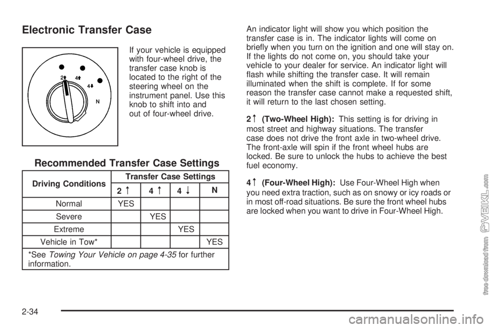
If your vehicle is equipped
with four-wheel drive, the
transfer case knob is
located to the right of the
steering wheel on the
instrument panel. Use this
knob to shift into and
out of four-wheel drive.
Recommended Transfer Case Settings
Driving ConditionsTransfer Case Settings
2m4m4nN
Normal YES
Severe YES
Extreme YES
Vehicle in Tow* YES
*SeeTowing Your Vehicle on page 4-35for further
information.An indicator light will show you which position the
transfer case is in. The indicator lights will come on
briefly when you turn on the ignition and one will stay on.
If the lights do not come on, you should take your
vehicle to your dealer for service. An indicator light will
flash while shifting the transfer case. It will remain
illuminated when the shift is complete. If for some
reason the transfer case cannot make a requested shift,
it will return to the last chosen setting.
2
m(Two-Wheel High):This setting is for driving in
most street and highway situations. The transfer
case does not drive the front axle in two-wheel drive.
The front-axle will spin if the front wheel hubs are
locked. Be sure to unlock the hubs to achieve the best
fuel economy.
4
m(Four-Wheel High):Use Four-Wheel High when
you need extra traction, such as on snowy or icy roads or
in most off-road situations. Be sure the front wheel hubs
are locked when you want to drive in Four-Wheel High.
2-34
Page 115 of 374
Instrument Panel Overview...............................3-4
Hazard Warning Flashers................................3-6
Other Warning Devices...................................3-6
Horn.............................................................3-6
Tilt Wheel.....................................................3-7
Turn Signal/Multifunction Lever.........................3-7
Turn and Lane-Change Signals........................3-8
Headlamp High/Low-Beam Changer..................3-8
Windshield Wipers..........................................3-9
Windshield Washer.......................................3-10
Cruise Control..............................................3-10
Exterior Lamps.............................................3-14
Headlamps on Reminder................................3-15
Daytime Running Lamps (DRL).......................3-15
Marker Lamps..............................................3-16
Instrument Panel Brightness...........................3-16
Dome Lamps...............................................3-16
Entry Lighting...............................................3-17
Reading Lamps............................................3-17
Instrument Panel Switchbank..........................3-18
Accessory Power Outlets...............................3-19
Ashtrays and Cigarette Lighter........................3-20
Climate Controls............................................3-20
Climate Control System.................................3-20
Outlet Adjustment.........................................3-23
Rear Heating System....................................3-24Warning Lights, Gages, and Indicators............3-24
Instrument Panel Cluster................................3-25
Speedometer and Odometer...........................3-26
Trip Odometer..............................................3-26
Tachometer.................................................3-26
Engine Speed Limiter....................................3-26
Safety Belt Reminder Light.............................3-27
Safety Belt Reminder Tone............................3-27
Airbag Readiness Light..................................3-27
Airbag Off Light............................................3-28
Charging System Light..................................3-30
Voltmeter Gage............................................3-30
Service Transmission Warning Light................3-31
Range Inhibit Warning Indicator......................3-31
Brake System Warning Light..........................3-31
Anti-Lock Brake System Warning Light.............3-34
Trailer Anti-Lock Brake System Warning Light.....3-34
Engine Coolant Temperature Gage..................3-35
Low Coolant Warning Light............................3-35
Wait to Start Indicator (Diesel Engine).............3-36
Malfunction Indicator Lamp.............................3-36
Oil Pressure Gage........................................3-37
Low Oil Level Light.......................................3-38
Change Engine Oil Light................................3-38
Engine Overspeed Warning Light....................3-39
Engine Shutdown Warning Light.....................3-39
Section 3 Instrument Panel
3-1
Page 145 of 374
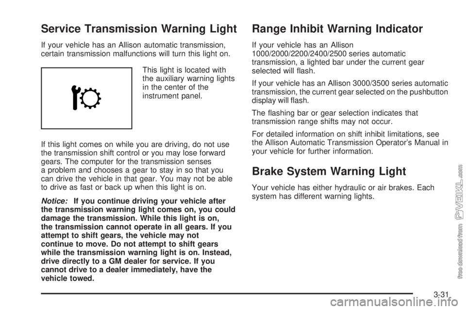
Service Transmission Warning Light
If your vehicle has an Allison automatic transmission,
certain transmission malfunctions will turn this light on.
This light is located with
the auxiliary warning lights
in the center of the
instrument panel.
If this light comes on while you are driving, do not use
the transmission shift control or you may lose forward
gears. The computer for the transmission senses
a problem and chooses a gear to stay in so that you
can drive the vehicle in that gear. You may not be able
to drive as fast or back up when this light is on.
Notice:If you continue driving your vehicle after
the transmission warning light comes on, you could
damage the transmission. While this light is on,
the transmission cannot operate in all gears. If you
attempt to shift gears, the vehicle may not
continue to move. Do not attempt to shift gears
while the transmission warning light is on. Instead,
drive directly to a GM dealer for service. If you
cannot drive to a dealer immediately, have the
vehicle towed.
Range Inhibit Warning Indicator
If your vehicle has an Allison
1000/2000/2200/2400/2500 series automatic
transmission, a lighted bar under the current gear
selected will flash.
If your vehicle has an Allison 3000/3500 series automatic
transmission, the current gear selected on the pushbutton
display will flash.
The flashing bar or gear selection indicates that
transmission range shifts may not occur.
For detailed information on shift inhibit limitations, see
the Allison Automatic Transmission Operator’s Manual in
your vehicle for further information.
Brake System Warning Light
Your vehicle has either hydraulic or air brakes. Each
system has different warning lights.
3-31
Page 150 of 374
Wait to Start Indicator
(Diesel Engine)
If your vehicle has the DURAMAX®6600, you will have
glow plugs. If your vehicle has the DURAMAX®7800,
you will have glow plugs and an inlet heater. If your
vehicle has a Caterpillar
®engine, you will have an
inlet heater.
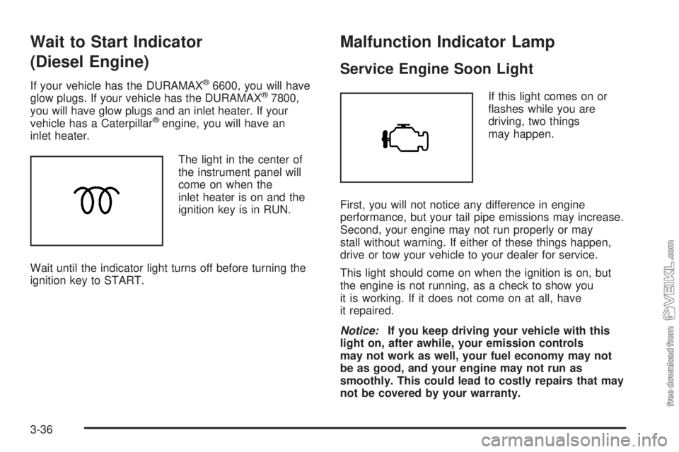
The light in the center of
the instrument panel will
come on when the
inlet heater is on and the
ignition key is in RUN.
Wait until the indicator light turns off before turning the
ignition key to START.
Malfunction Indicator Lamp
Service Engine Soon Light
If this light comes on or
flashes while you are
driving, two things
may happen.
First, you will not notice any difference in engine
performance, but your tail pipe emissions may increase.
Second, your engine may not run properly or may
stall without warning. If either of these things happen,
drive or tow your vehicle to your dealer for service.
This light should come on when the ignition is on, but
the engine is not running, as a check to show you
it is working. If it does not come on at all, have
it repaired.
Notice:If you keep driving your vehicle with this
light on, after awhile, your emission controls
may not work as well, your fuel economy may not
be as good, and your engine may not run as
smoothly. This could lead to costly repairs that may
not be covered by your warranty.
3-36
Page 155 of 374
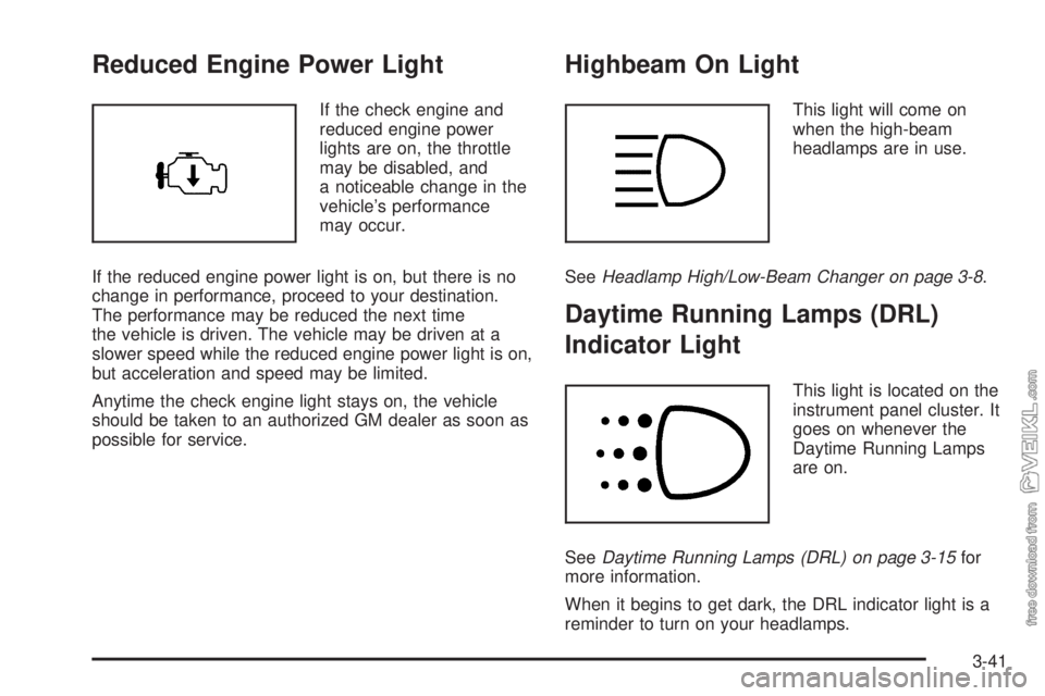
Reduced Engine Power Light
If the check engine and
reduced engine power
lights are on, the throttle
may be disabled, and
a noticeable change in the
vehicle’s performance
may occur.
If the reduced engine power light is on, but there is no
change in performance, proceed to your destination.
The performance may be reduced the next time
the vehicle is driven. The vehicle may be driven at a
slower speed while the reduced engine power light is on,
but acceleration and speed may be limited.
Anytime the check engine light stays on, the vehicle
should be taken to an authorized GM dealer as soon as
possible for service.
Highbeam On Light
This light will come on
when the high-beam
headlamps are in use.
SeeHeadlamp High/Low-Beam Changer on page 3-8.
Daytime Running Lamps (DRL)
Indicator Light
This light is located on the
instrument panel cluster. It
goes on whenever the
Daytime Running Lamps
are on.
SeeDaytime Running Lamps (DRL) on page 3-15for
more information.
When it begins to get dark, the DRL indicator light is a
reminder to turn on your headlamps.
3-41
Page 172 of 374
Care of the Cassette Tape Player
A tape player that is not cleaned regularly can cause
reduced sound quality, ruined cassettes or a damaged
mechanism. Cassette tapes should be stored in their
cases away from contaminants, direct sunlight and
extreme heat. If they aren’t, they may not operate
properly or may cause failure of the tape player.
The tape player should be cleaned regularly after every
50 hours of use. The radio may display CLN to
indicate that the tape player has been used for 50 hours
without resetting the tape clean timer. If this message
appears on the display, the cassette tape player
needs to be cleaned. It will still play tapes, but it should
be cleaned as soon as possible to prevent damage
to the tapes and player. If there is a reduction in sound
quality, try a known good cassette to see if the tape
or the tape player is at fault. If this other cassette has no
improvement in sound quality, clean the tape player.
For best results, use a scrubbing action, non-abrasive
cleaning cassette with pads which scrub the tape
head as the hubs of the cleaner cassette turn. The
recommended cleaning cassette is available through
your dealer.The cut tape detection feature of the cassette tape
player may identify the cleaning cassette as a damaged
tape. To prevent the cleaning cassette from being
ejected, use the following steps:
1. Turn the ignition on.
2. Turn the radio off.
3. Press and hold the TAPE button for two seconds
until the radio produces one beep. CAS will flash
on the display for five seconds.
4. Insert the scrubbing action cleaning cassette.
5. Eject the cleaning cassette after the manufacturer’s
recommended cleaning time.
After the cleaning cassette is ejected, the cut tape
detection feature will be active again.
A non-scrubbing action, wet-type cleaner which uses a
cassette with a fabric belt to clean the tape head
can be used. This type of cleaning cassette will not
eject on its own. A non-scrubbing action cleaner may not
clean as thoroughly as the scrubbing type cleaner.
The use of a non-scrubbing action, dry-type cleaning
cassette is not recommended.
After the player is cleaned, press and hold the eject
button for three seconds to reset the CLN indicator. The
radio will display --- to show the indicator was reset.
Cassettes are subject to wear and the sound quality may
degrade over time. Always make sure the cassette
tape is in good condition before the tape player
is serviced.
3-58
Page 219 of 374
Gasolines containing oxygenates, such as ethers and
ethanol, and reformulated gasolines may be available in
your area to contribute to clean air. General Motors
recommends that you use these gasolines, particularly if
they comply with the specifications described earlier.
Notice:Your vehicle was not designed for fuel that
contains methanol. Do not use fuel containing
methanol. It can corrode metal parts in your fuel
system and also damage the plastic and rubber
parts. That damage would not be covered under
your warranty.
Some gasolines that are not reformulated for low
emissions may contain an octane-enhancing additive
called methylcyclopentadienyl manganese tricarbonyl
(MMT); ask the attendant where you buy gasoline
whether the fuel contains MMT. General Motors
does not recommend the use of such gasolines.
Fuels containing MMT can reduce the life of spark plugs
and the performance of the emission control system
may be affected. The malfunction indicator lamp
may turn on. If this occurs, return to your authorized
GM dealer for service.Diesel Engine Fuel
For the Caterpillar®diesel, see the Caterpillar®
Operation & Maintenance Manual for information
concerning fuel usage.
Notice:Diesel fuel or fuel additives not
recommended in this manual could damage your
fuel system and engine. Your warranty would
not cover this damage. And:
Diesel fuel that has been mixed with engine oil
or automatic transmission �uid could damage
your engine and emission controls.
Aftermarket diesel fuel additives are not tested
by General Motors. Some additives, particularly
those which contain alcohol or water emulsi�ers,
may damage your fuel system. If you believe that
unique circumstances call for a fuel additive to
be used, consult your dealer for advice.
If you ever run out of diesel fuel, it can be difficult
to restart your engine. To avoid all this, never let
your tank get empty.
If gasoline is ever accidentally added to the fuel
tank, to avoid severe engine damage, do not run the
engine until the fuel tank can be drained.
If you run out of fuel,Running Out of Fuel on page 5-15
tells you how to restart your engine.
5-7