lock CHEVROLET LOW CAB FORWARD 2017 Owner's Manual
[x] Cancel search | Manufacturer: CHEVROLET, Model Year: 2017, Model line: LOW CAB FORWARD, Model: CHEVROLET LOW CAB FORWARD 2017Pages: 414, PDF Size: 7.97 MB
Page 289 of 414

Chevrolet Low Cab Forward Owner Manual (GMNA-Localizing-U.S.-
10716700) - 2017 - crc - 12/6/16
288 Vehicle Care
2. Continue pushing in the wiperrubber insert until the wiper
blade's hook engages with the
hole in it, and then confirm that
the rubber insert is securely
held in place.
3. Attach the wiper blade to the wiper arm.Headlamp Aiming
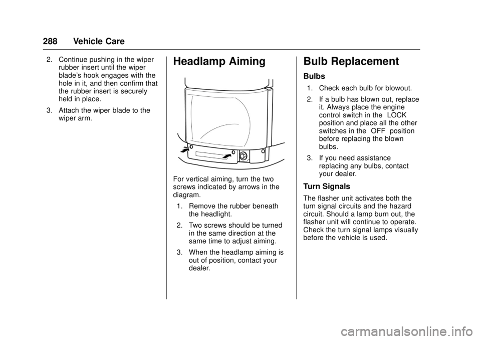
For vertical aiming, turn the two
screws indicated by arrows in the
diagram.
1. Remove the rubber beneath the headlight.
2. Two screws should be turned in the same direction at the
same time to adjust aiming.
3. When the headlamp aiming is out of position, contact your
dealer.
Bulb Replacement
Bulbs
1. Check each bulb for blowout.
2. If a bulb has blown out, replaceit. Always place the engine
control switch in the “LOCK”
position and place all the other
switches in the “OFF”position
before replacing the blown
bulbs.
3. If you need assistance replacing any bulbs, contact
your dealer.
Turn Signals
The flasher unit activates both the
turn signal circuits and the hazard
circuit. Should a lamp burn out, the
flasher unit will continue to operate.
Check the turn signal lamps visually
before the vehicle is used.
Page 295 of 414

Chevrolet Low Cab Forward Owner Manual (GMNA-Localizing-U.S.-
10716700) - 2017 - crc - 12/6/16
294 Vehicle Care
3. To install the lamps, performthe same sequence of
operations in reverse, taking
care to turn the connector
clockwise to lock it securely.
If the socket is not locked securely,
water could get inside the lamp and
lead to a breakdown.
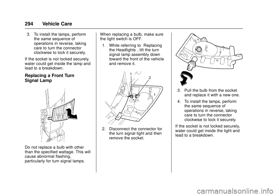
Replacing a Front Turn
Signal Lamp
Do not replace a bulb with other
than the specified wattage. This will
cause abnormal flashing,
particularly for turn signal lamps. When replacing a bulb, make sure
the light switch is OFF.
1. While referring to “Replacing
the Headlights”, tilt the turn
signal lamp assembly down
toward the front of the vehicle
and remove it.
2. Disconnect the connector for the turn signal light and then
remove the socket.
3. Pull the bulb from the socketand replace it with a new one.
4. To install the lamps, perform the same sequence of
operations in reverse, taking
care to turn the connector
clockwise to lock it securely.
If the socket is not locked securely,
water could get inside the light and
lead to a breakdown.
Page 297 of 414

Chevrolet Low Cab Forward Owner Manual (GMNA-Localizing-U.S.-
10716700) - 2017 - crc - 12/6/16
296 Vehicle Care
3. When the clip (1) has beenremoved, pull the lamp out
while sliding it out toward the
rear of the vehicle.
4. Loosen the socket by turning it counterclockwise.5. Pull the bulb out from the
socket and replace it with a
new one.
6. To install the lights, perform the same sequence of operations
in reverse taking care of the
following points:
A. Turn the socket clockwiseto lock securely.
If the socket is not locked
securely, water could get
inside the light and lead to
a breakdown.B. Insert the clip on the backof the rear part of the light
into the door panel.
C. Push the front part of the light into the door panel,
and insert the clip on the
back of the front part of the
light in the door panel.
Page 298 of 414

Chevrolet Low Cab Forward Owner Manual (GMNA-Localizing-U.S.-
10716700) - 2017 - crc - 12/6/16
Vehicle Care 297
D. Open the front door, tightenthe nut from the inside of
the door, and install the
rubber cap.
Taillamps, Turn Signal,
Stoplamps, and Back-Up
Lamps
1. Turn Signal Lamp
2. Taillamp/Stoplamp
3. Back-Up Lamp
4. Lens
1. Loosen the screws and remove the lens.
2. Loosen the bulb by turning it counterclockwise while
pressing on it.
3. To install the lights, follow the removal procedure in reverse.
License Plate Lamp
1. Bulb
2. Lens
3. Screw
4. Cover
1. Loosen the screws and removethe cover.
2. Remove the lens.
3. Loosen the bulb by turning it counterclockwise while
pressing on it.
4. To install the lights, follow the removal procedure in reverse.
Page 300 of 414

Chevrolet Low Cab Forward Owner Manual (GMNA-Localizing-U.S.-
10716700) - 2017 - crc - 12/6/16
Vehicle Care 299
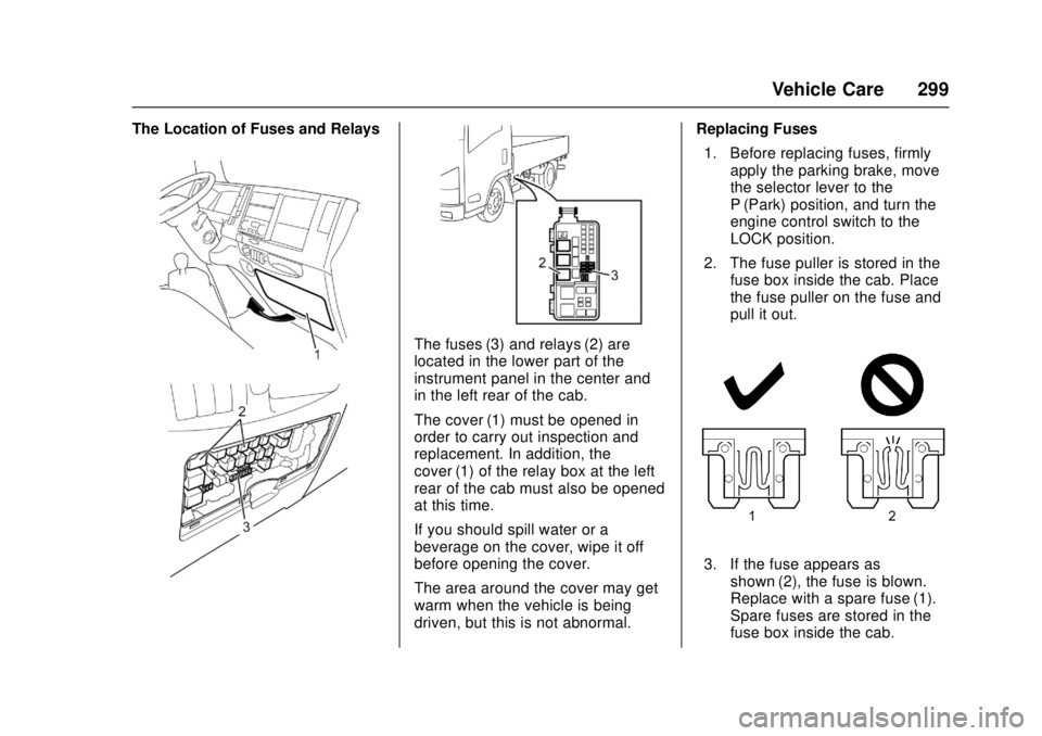
The Location of Fuses and Relays
The fuses (3) and relays (2) are
located in the lower part of the
instrument panel in the center and
in the left rear of the cab.
The cover (1) must be opened in
order to carry out inspection and
replacement. In addition, the
cover (1) of the relay box at the left
rear of the cab must also be opened
at this time.
If you should spill water or a
beverage on the cover, wipe it off
before opening the cover.
The area around the cover may get
warm when the vehicle is being
driven, but this is not abnormal.Replacing Fuses
1. Before replacing fuses, firmly apply the parking brake, move
the selector lever to the
P (Park) position, and turn the
engine control switch to the
LOCK position.
2. The fuse puller is stored in the fuse box inside the cab. Place
the fuse puller on the fuse and
pull it out.
3. If the fuse appears asshown (2), the fuse is blown.
Replace with a spare fuse (1).
Spare fuses are stored in the
fuse box inside the cab.
Page 302 of 414

Chevrolet Low Cab Forward Owner Manual (GMNA-Localizing-U.S.-
10716700) - 2017 - crc - 12/6/16
Vehicle Care 301
Fuse and Relay Location–Cab InteriorFuse locations:
No. Description Rating
1 RR P / WINDOW 25A
2 – –
3 ROOM LAMP, AUDIO 10A
4 DOOR LOCK 15A
5 TRAILER BRAKE 15A
6 P/ WINDOW 25A
7 ABS 10A
8 WIPER 25A
9 H / LAMP LO (LH) 10A
10 LAMPS (BATT) 10A 11 H / LAMP LO (RH) 10A
12 BRAKE LAMPS 10A
13 STARTER 10A
14 H / LAMP HI (LH) 10A
15 H / LAMP HI (RH) 10A
Page 320 of 414

Chevrolet Low Cab Forward Owner Manual (GMNA-Localizing-U.S.-
10716700) - 2017 - crc - 12/6/16
Vehicle Care 319
Warning (Continued)
gas engines, to learn which
wheels and tires are correct, look
at the "Vehicle Certification and
Greenhouse Gas (GHG)
Emissions Plate" on the left side
rear pillar panel below the striker
(single cab) or on the left center
pillar panel beside the shoulder
seat belt anchor (crew cab).
Wheel size is also stamped on
the side of each wheel.
To help avoid personal injury and
property damage if a wheel must
be changed, seek expert tire
services if you can. If you must
remove the wheel without any
such help, do the following:. If the tire looks as if it may
be underinflated, stand to
the side and check whether
the wheel assembly
appears normal by
comparing it to another
wheel assembly on the
vehicle.
(Continued)
Warning (Continued)
.Let the air out of the tire by
taking out the valve core.
If you have a way to put air
back in a tire, note that it is
good safety practice to let
the air out of both tires of a
dual assembly before taking
off the damaged tire and rim
assembly from the vehicle.
After letting out the air, take
off the tire and rim assembly
and install a spare tire and
rim assembly.
If your vehicle is equipped
with a differential lock
system or limited slip
differential (LSD), it might
start moving when the
engine power is transmitted
to the rear axle even when
one of the wheels on the
axle is raised clear of the
ground. Do not start the
engine with any rear wheel
in contact with the ground.
(Continued)
Warning (Continued)
If you are not fully
experienced on the
procedures to follow, and/or
are not equipped with the
proper tools and equipment,
again, do not attempt to
raise the vehicle, or remove
or install the tire and wheel
assembly—seek expert tire
services.
. Do not put air back in a tire
that has been run flat, or is
seriously low on air, without
first having the tire taken off
the wheel and the tire
checked for damage.
. Note that taking off and
mounting tires on wheels
requires proper tools, safety
equipment and special
training. A person can be
severely injured or killed
and damage can result from
using the wrong service
methods. Truck tires and
(Continued)
Page 329 of 414

Chevrolet Low Cab Forward Owner Manual (GMNA-Localizing-U.S.-
10716700) - 2017 - crc - 12/6/16
328 Vehicle Care
Warning (Continued)
Never tow the vehicle to start
because a surge forward when
the engine starts could cause a
collision with the tow vehicle.
Also, this vehicle has a 12-volt
battery, 12-volt starting system
and a negative ground electrical
system; be sure the vehicle or
equipment used to jump start your
engine is also 12-volt. Use of any
other system may damage the
vehicle's electrical components.
Under no circumstances should
the battery's positive and negative
terminals be put in contact with
one another.
When connecting the cables,
under no circumstances should
the clips be allowed to touch each
other.(Continued)
Warning (Continued)
Do not disconnect a battery
terminal with the engine running.
It could cause a breakdown in the
electrical system.
You and others could be seriously
injured.
If you notice battery fluid leaking,
have an inspection carried out
immediately by the nearest dealer.
Diesel engine vehicles have more
than one battery because of the
higher torque required to start a
diesel engine. This procedure can
be used to start a single-battery
vehicle from any of the diesel
vehicle's batteries. However, at low
temperatures, it may not be possible
to start a diesel engine from a single
battery from another vehicle. 1. Use a vehicle that has a charged battery with the same
voltage. Make sure that the
other vehicle also has a 12-volt
starting system, and that it is the negative (–) terminal which
is grounded (attached to the
engine block, or frame rail).
2. Position the vehicle with the good (charged) battery so that
the booster (jumper) cables will
reach. But never let the
vehicles touch. Also, be sure
the booster cables to be used
do not have loose or missing
insulation.
3. In both vehicles, turn off the ignition (engine control) switch
and all lights and accessories
except the hazard flasher or
any lights needed for the work
area. In both vehicles, apply
the parking brake firmly and
move the selector lever to the
"P" position.
Page 333 of 414

Chevrolet Low Cab Forward Owner Manual (GMNA-Localizing-U.S.-
10716700) - 2017 - crc - 12/6/16
332 Vehicle Care
Towing the Vehicle
Consult your dealer or a
professional towing service if the
disabled vehicle must be towed.
Proper equipment must be used to
prevent damage to vehicles during
any towing. State and local laws
which apply to vehicles in tow must
be followed. Vehicles should not be
towed at speeds in excess of
88 km/h (55 mph).
Connect to the main structural parts
of the vehicle. Do not attach to
bumpers, tow hooks or brackets.
Use only equipment designed for
this purpose. Follow the instructions
of the wrecker manufacturer.
A safety chain system must
be used.
The procedures below must be
followed when towing to prevent
possible damage.Front End Towing (Front Wheels
Off Ground)
To prepare a disabled vehicle for
front end towing with front wheels
raised off theground, the following
steps are necessary:
.
Block the rear wheels of the
disabled vehicle.
. For gasoline vehicles, move the
selector lever into "N" position,
vehicles can be towed at speeds
below 48 km/h (30 mph) and up
to distances less than
80 km (50 mi).
. Disconnect the driveshaft at the
rear axle. Secure the driveshaft
to the frame or crossmember.
When towing, disconnect the
driveshaft at the rear axle to ensure
the transmission is not damaged.
The rear end of the driveshaft must
be disconnected and safely secured
if the 80 km (50 mi) or 48 km/h
(30 mph) is exceeded. If there is damage or suspected
damage to the rear axle, remove the
axle shafts. Cover the hub openings
to prevent the loss of lubricant or
entry of dirt or foreign objects.
Place a 10 cm (4 in) wood beam
against the towing guide behind the
bumper. (If no 10 cm (4 in) is
available, then remove the bumper.)
Ensure towing chains do not come
into contact with the horns or the
bumper. (If towing chains contact
the bumper, then remove the
bumper.)
1. Horns
2. Bumper
Page 334 of 414

Chevrolet Low Cab Forward Owner Manual (GMNA-Localizing-U.S.-
10716700) - 2017 - crc - 12/6/16
Vehicle Care 333
After Towing
After towing the vehicle, block the
rear wheels and install axle shafts
or driveshaft.
Apply the parking brake before
disconnecting from the towing
vehicle.
Front End Towing (All Wheels On
the Ground)
Your vehicle may be towed on all
wheels provided the steering is
operable. Remember that power
steering and brakes will not have
power assist. There must be a tow
bar installed between the tow
vehicle and the disabled vehicle.
Towing with all wheels on theground
1. Bumper
2. Tow Hook
3. Front Axle
4. Towing Guide
5. Towing Chain
To prepare a disabled vehicle for
front end towing with all wheels on
the ground, the following steps are
necessary:
.Block the rear wheels of the
disabled vehicle.
. For gasoline vehicles, move the
selector lever into "N" position,
vehicles can be towed at speeds below 48 km/h (30 mph) and up
to distances less than
80 km (50 mi).
. Disconnect the driveshaft at the
rear axle. Secure the driveshaft
to the frame or crossmember.
When towing, disconnect the
driveshaft at the rear axle to ensure
the transmission is not damaged.
The rear end of the driveshaft must
be disconnected and safely secured
if the 80 km (50 mi) or 48 km/h
(30 mph) is exceeded.
Provide wood blocking to prevent
towing chains and bar from coming
into contact with the bumper.
If there is damage or suspected
damage to the rear axle, remove the
axle shafts.
Cover the hub openings to prevent
the loss of lubricant or entry of dirt
or foreign objects.
After Towing
After towing the vehicle, block the
rear wheels and install axle shafts
or driveshaft.