engine CHEVROLET MONTE CARLO 1973 2.G Owner's Guide
[x] Cancel search | Manufacturer: CHEVROLET, Model Year: 1973, Model line: MONTE CARLO, Model: CHEVROLET MONTE CARLO 1973 2.GPages: 86, PDF Size: 33.46 MB
Page 31 of 86
Downloaded from www.Manualslib.com manuals search engine _ '\' ' 2
1
5 , / '/ ,
[ e /~
O'v RPM !lOa -"-50
Optional Instrument and
Gauges
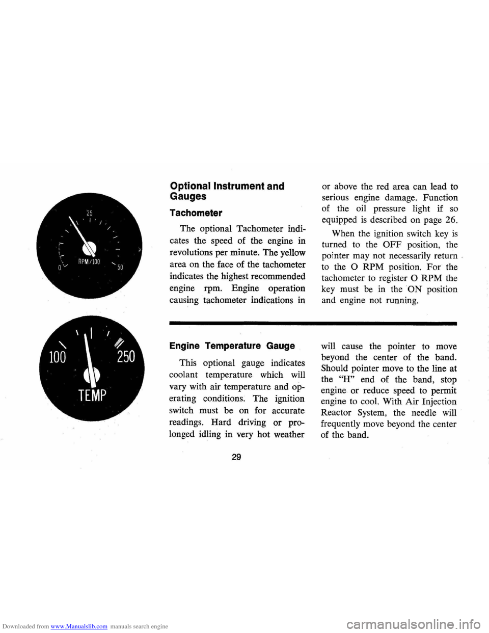
Tachometer
The optional Tachometer indi
cates the speed of the engine in
revolutions per minute. The yellow
area on the face of the tachometer
indicates the highest recommended
engine rpm. Engine operation
causing tachometer indications in
Engine Temperature Gauge
This optional gauge indicates
coolant temperature which will
vary with air temperature and op
erating conditions. The ignition
switch must be on for accurate
readings. Hard driving
or pro
longed idling in very hot weather
29
or above the red area can lead to
serious engine damage. Function
of the oil pressure light if
so
equipped is described on page 26.
When the ignition switch key
is
turned to the OFF position, the
pointer may not necessarily return
'
to the 0 RPM position. For the
tachometer
to register 0 RPM the
key must be in the
ON position
and engine not running.
will cause the pointer to move
beyond the center of the band.
Should pointer move to the line at
the
"H" end of the band, stop
engine
or reduce speed to permit
engine to cool. With Air Injection
Reactor System, the needle will
frequently move beyond the center
of the band.
Page 32 of 86
Downloaded from www.Manualslib.com manuals search engine I I
' /
D C
4 t '
AMPS
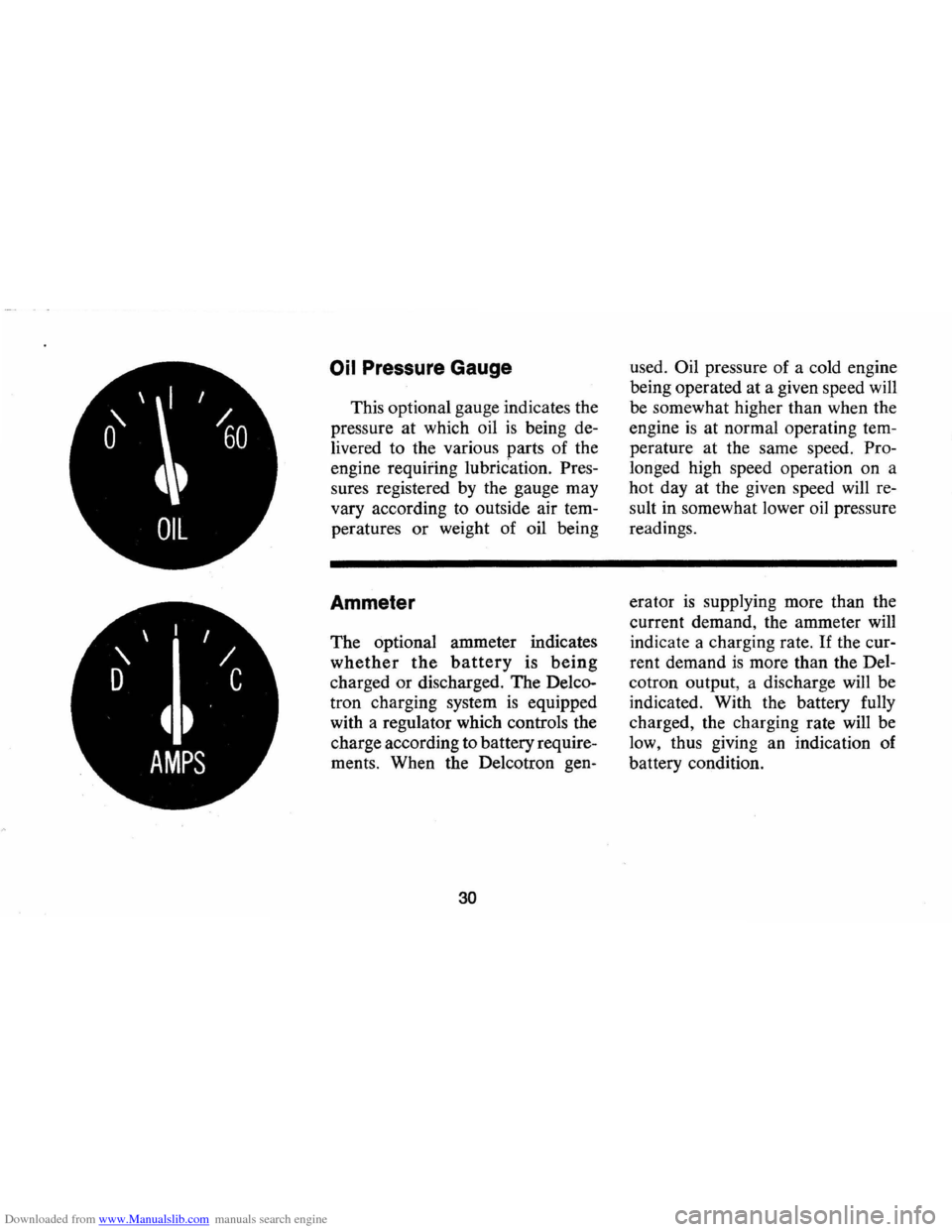
Oil Pressure Gauge
This optional gauge indicates the
pressure at which oil
is being de
livered to the various parts of the
engine
requiting lubriCation. Pres
sures registered by the gauge may
vary according to outside air tem
peratures
or weight of oil being
Ammeter
The optional ammeter indicates
whether the battery is being
charged or discharged. The Delco
tron charging system
is equipped
with a regulator which controls the
charge according to battery require
ments . When the Delcotron gen-
30
used. Oil pressure of a cold engine
being operated at a given speed will
be somewhat higher than when the
engine
is at normal operating tem
perature at the same speed. Pro
longed high speed operation on a
hot day at the given speed will re
sult in somewhat lower oil pressure
readings.
era tor
is supplying more than the
current demand, the ammeter
will
indicate a charging rate. If the cur
rent demand
is more than the Del
cotron output, a discharge will be
indicated. With the battery fully
charged, the charging rate will be
low, thus giving an indication of
battery condition.
Page 33 of 86
Downloaded from www.Manualslib.com manuals search engine Clock
Reset the clock , by pulling out
the knob and turning the hands
clockwise
if slow, counterclockwise
if fast. This will, if the clock error
is five minutes or more, automati
cally compensate for time gain or
lag . Several resettings, several days
apart, may be needed to propertly
adjust the clock mechanism. Have
your clock cleaned and oiled by a
competent clock serviceman at
least every two years.
Cigarette Lighter
The cigarette lighter is located
on the instrument panel face.
To
operate, push it in. When it be
comes heated, it automatically pops
out ready for use.
Windshield Wiper and
Washer
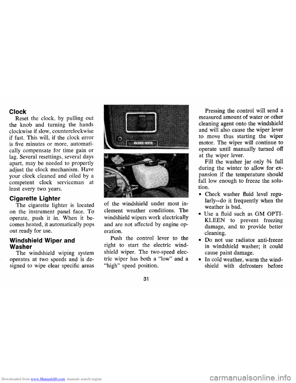
The windshield wiping system
operates at two speeds and
is de
signed to wipe clear specific areas of
the windshield under most in
clement weather conditions . The
windshield wipers work electrically
and are not affected by engine op
eration. Push the control lever to the
right to start the electric wind
shield wiper. The two-speed elec
tric wiper has both a "low" and a
"high" speed position.
31
Pressing the control will send a
measured amount of water or other
cleaning agent onto the windshield
and will also cause the wiper lever
to move thus starting the wiper
motor. The wiper will continue to
operate until manually turned off
at the wiper lever.
Fill the washer jar only
% full
during the winter to allow for ex
pansion if the temperature should
fall low enough to freeze the solu
tion .
• Check washer fluid level regu
larly-do it frequently when the
weather is bad .
• Use a fluid such as GM OPTI
KLEEN to prevent freezing
damage, and to provide better
cleaning.
• Do not use radiator anti-freeze
in windshield washer; it could
cause paint damage.
• In cold weather, warm the wind
shield with defrosters before
Page 34 of 86
Downloaded from www.Manualslib.com manuals search engine VENT
CONTROLS
using washer -to help prevent
icing that may seriously obscure
vision.
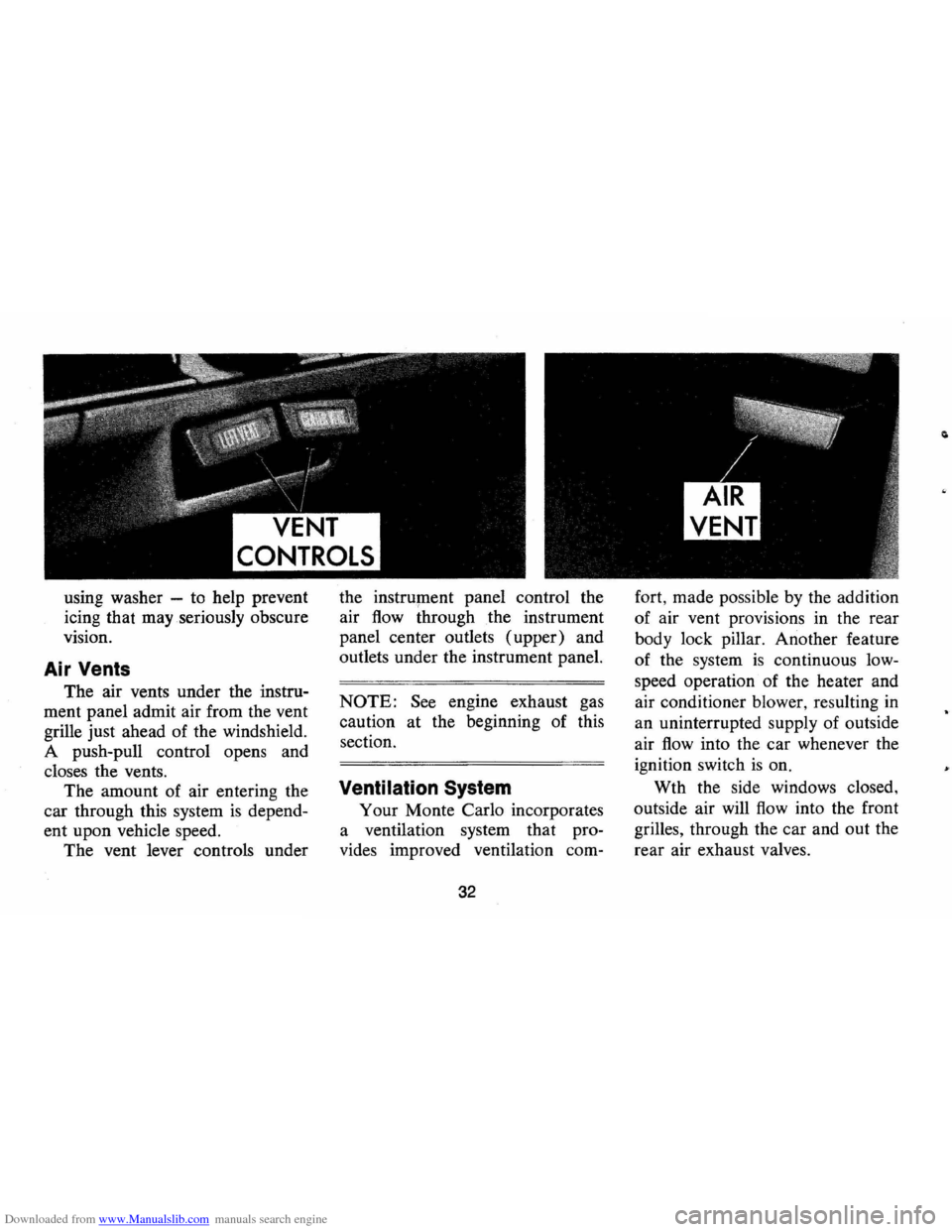
Air Vents
The air vents under the instru
ment panel admit air from the vent
grille just ahead of the windshield.
A push-pull control opens and
closes the vents.
The amount of air entering the
car through this system
is depend
ent upon vehicle speed.
The vent lever controls under the
instrument panel control the
air
flow through the instrument
panel center outlets (upper) and
outlets under the instrument panel.
NOTE: See engine exhaust gas
caution at the beginning of this
section.
Ventilation System
Your Monte Carlo incorporates
a ventilation system that pro
vides improved ventilation com-
32
fort, made possible by the addition
of air vent provisions in the rear
body lock pillar. Another feature
of the system
is continuous low
speed operation of the heater and
air conditioner blower, resulting
in
an uninterrupted supply of outside
air
flow into the car whenever the
ignition switch
is on.
Wth the side windows closed,
outside air will
flow into the front
grilles, through the car and out the
rear air exhaust valves.
Page 35 of 86
Downloaded from www.Manualslib.com manuals search engine Basic Operating Tips:
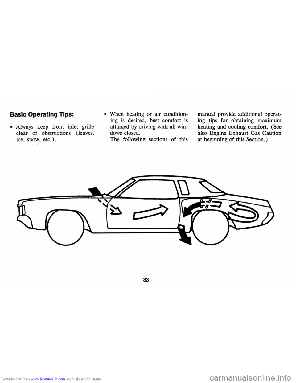
• Always keep front inlet grille
clear of obstructions (leaves,
ice, snow, etc.).
• When heating or air condition
ing
is desired, best comfort is
attained by driving with all win
dows closed.
The following sections of this
33
manual provide additional operat
ing tips for obtaining maximum
heating and cooling comfort.
(See
also Engine Exhaust Gas Caution
at beginning of this
Section.)
Page 36 of 86
Downloaded from www.Manualslib.com manuals search engine Heater
The windshield defrosting and
defogging system assists in provid
ing good visibility through desig
nated areas of the windshield under
most inclement weather conditions.
For immediate operation of the ve
hicle , the windshield should be
scraped clear.
Lower Lever
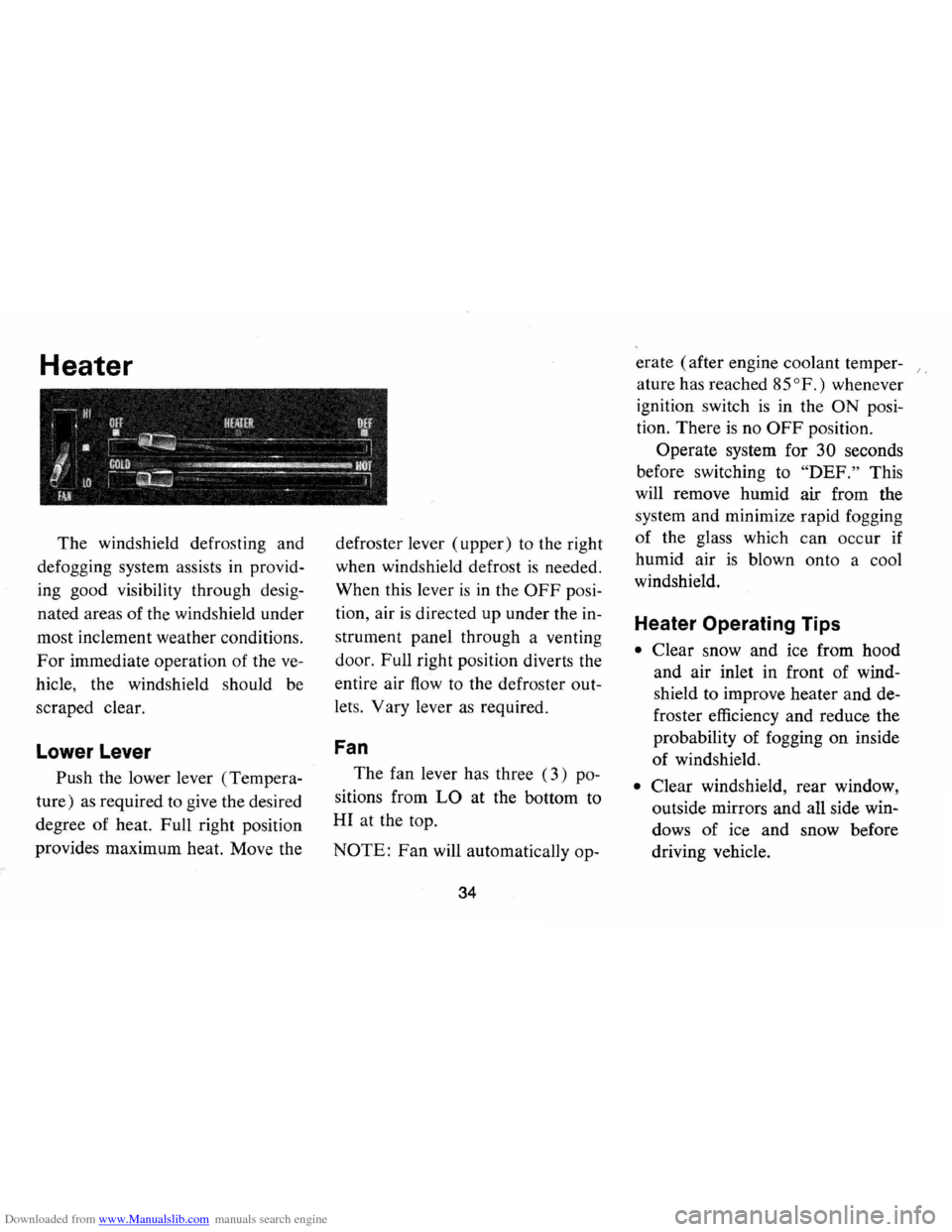
Push the lower lever (Tempera
ture)
as required to give the desired
degree of heat. Full right position
provides maximum heat. Move the defroster
lever (upper) to the right
when windshield defrost
is needed.
When this lever
is in the OFF posi
tion , air
is directed up under the in
strument panel through a venting
door. Full right position diverts the
entire air
flow to the defroster out
lets. Vary lever
as required.
Fan
The fan lever has three (3) po
sitions from
LO at the bottom to
HI at the top.
NOTE: Fan will automatically op-
34
erate (after engine coolant temper- /,
ature has reached 85°
F.) whenever
ignition switch
is in the ON posi
tion. There
is no OFF position.
Operate system for
30 seconds
before switching to
"DEF." This
will remove humid air from the
system and minimize rapid fogging
of the glass which
can occur if
humid air
is blown onto a cool
windshield.
Heater Operating Tips
• Clear snow and ice from hood
and air inlet in front of wind
shield to improve heater and de
froster efficiency and reduce the
probability of fogging on inside
of windshield.
• Clear windshield, rear window,
outside mirrors and all side win
dows
of ice and snow before
driving vehicle.
Page 37 of 86
Downloaded from www.Manualslib.com manuals search engine • Operate blower on "HIGH" for
a
few seconds before moving the
vehicle, to clear the intake ducts
of snow.
• Keep all windows and vents
closed to reduce dust, road and
wind noise and uncomfortable
drafts.
• For most satisfactory heater op
eration and air circulation, op
erate fan on low
or medium
speeds for normal operation and
high speed for quick warm-up
and during extremely low temp
eratures.
• For adequate rear seat heating,
the area beneath the front seat
must not be blocked
by carpet
ing, rags, paper or other ma
terial and fan should operate on
high blower.
Rear Window Defroster
To ensure clear vision through
the rear window during inclement weather,
the Rear Window De
froster
is optionally available. This
unit draws
in air from the pas
senger compartment and directs it against
the back window to remove
frost or moisture. Its blower has a
two-speed control switch on the
instrument panel.
Four Season Air Conditioning System
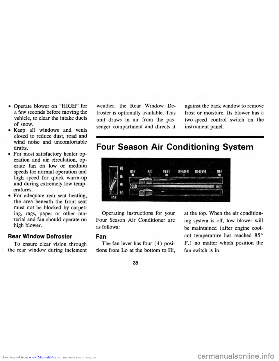
Operating instructions for your
Four Season Air Conditioner are
as follows:
Fan
The fan lever has four (4) posi
tions from Lo at the bottom to Hi,
35
at the top. When the air condition
ing system
is off, low blower will
be maintained (after engine cool
ant temperature has reached
85°
F.) no matter which position the
fan switch
is in.
Page 38 of 86
Downloaded from www.Manualslib.com manuals search engine Temperature (Lower Lever)
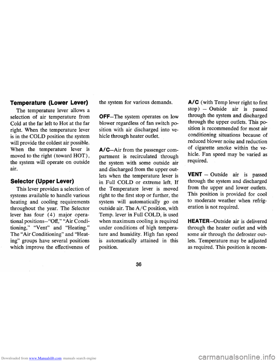
The temperature lever allows a
selection of air temperature from
Cold at the far left to Hot
at the far
right. When the temperature lever
is in the COLD position the system
will provide the coldest air possible.
When the temperature lever
is
moved to the right (toward HOT) ,
the system will operate on outside
air.
Selector (Upper Lever)
This lever provides a selection of
systems available to handle various
heating and cooling requirements
throughout the year. The Selector
lever has four
(4) major opera
tional
positions-"Off," "Air Condi
tioning," "Vent" and "Heating."
The "Air Conditioning" and "Heat
ing"
groups have several positions
which improve the effectiveness of the
system for various demands.
OFF-The system operates on low
blower regardless of fan switch po
sition with air discharged into
ve
hicle through heater outlet.
A/C-Air from the passenger com
partment
is recirculated through
the system with some outside air
and discharged from the upper out
lets when the temperature lever
is
in Full COLD or extreme left. If
the Temperature lever is moved
right to the first stop or further, the
system will automatically go on
outside air. The
AIC position, with
Temp. lever in Full
COLD, is used
when maximum cooling
is required
under conditions of high tempera
ture and humidity. High fan speed
is automatically attained in this
position .
36
A/C (with Temp lever right to first
stop) -Outside air
is passed
through the system and discharged
through the upper outlets. This po
sition
is recommended for most air
conditioning situations because of
reduced blower noise and reduction
of cigarette smdke within the
ve
hicle. Fan speed may be varied as
required.
VENT -Outside air is passed
through the system and discharged
from the upper and lower outlets.
This position
is provided for cool
to moderate weather when refrig
eration
is not required.
HEATER-Outside air
is delivered
through the heater outlet and with
some air through the defroster out
lets. Temperature may be adjusted
as required. This position is recom-
Page 39 of 86
Downloaded from www.Manualslib.com manuals search engine mended for most winter driving.
BI-LEVEL -Outside air is deliv
ered from the heater lower outlet
and the defroster duct and upper
outlets to provide comfort and keep
the windshield and side glass clear
under low fogging conditions.
DEF -Outside air is delivered
through the defroster outlets only.
Temperature and blower speeds
may be adjusted
as required. This
position
is recommended for condi
tions of severe fogging and icing
only.
Four Season System
Air
Outlets
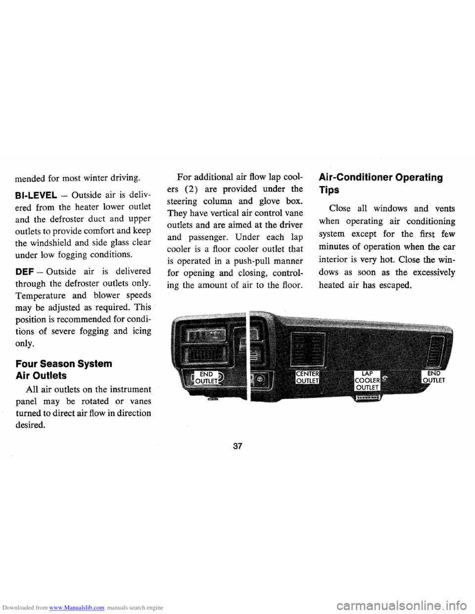
All air outlets on the instrument
panel may be rotated
or vanes
turned to direct air
flow in direction
desired.
For additional air flow lap cool
ers
(2) are provided under the
steering column and glove box.
They have vertical air control vane
outlets and are aimed at the driver
and passenger. Under each lap
cooler
is a floor cooler outlet that
is operated in a push-pull manner
for opening and closing, control
ing the amount of air to the floor.
37
Air-Conditioner Operating
Tips
Close all windows and vents
when operating air conditioning
system except for the first
few
minutes of operation when the car
interior
is very hot. Close the win
dows
as soon as the excessively
heated air has escaped.
Page 40 of 86
Downloaded from www.Manualslib.com manuals search engine Chevrolet HAil Transistor" Radios
To operate the radios, the igni
tion switch must be in "ON" or
"ACC" position.
r------_·_-
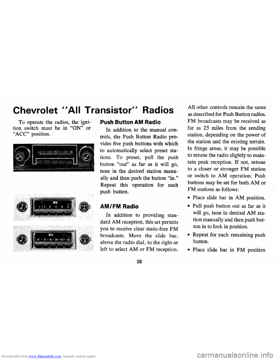
Push Butt.on AM Radio
In addition to the manual con
trols , the Push Button Radio pro
vides five push buttons with which
to automatically select preset
sta
tions. To preset , pull the push
button
"out" as far as it will go,
tune in the desired station
manu
ally and then push the button "in."
Repeat this operation for each
push button.
!, 11111, II >, -ij 10 1/ Il '" I 1 AM/FM Radio
I.:"" :~ ;:--'.-'.-:'---~ -
.--.. -WI .. il~ • q2 -f~6 -lor ~ lOl -loa ~~,.."... -~-~.-.. ---_ ll'1 S. ...
In addition to providing stan
dard AM reception, this set permits
you to receive clear static-free
FM
broadcasts. Move the slide bar ,
above the radio dial, to the right or
left to select AM or FM reception.
38
All other controls remain the same
as described for Push Button radios.
FM broadcasts may be received as
far as 25 miles from the sending
station , depending on the power of
the station and the existing terrain.
In fringe areas, it may
be possible
to retune the radio slightly to
main
tain peak reception . If not, retune
to a closer or stronger
FM station
or switch to AM operation. Push
buttons may be set for both
AM or
FM stations as follows:
• Place slide bar in AM position.
• Pull push button out as far as it
will go, tune in desired AM
sta
tion manually and then push but
ton in to lock in position.
• Repeat for each remaining push
button.
• Place slide bar in FM position