ignition CHEVROLET MONTE CARLO 1973 2.G Owners Manual
[x] Cancel search | Manufacturer: CHEVROLET, Model Year: 1973, Model line: MONTE CARLO, Model: CHEVROLET MONTE CARLO 1973 2.GPages: 86, PDF Size: 33.46 MB
Page 5 of 86
Downloaded from www.Manualslib.com manuals search engine BEFORE DRIVING YOUR MONTE CARLO
DRIVER CHECKLIST
Before Entering Car
1. See that windows , mirrors and
lights are clean.
2 . Visually note inflation condition
of tires.
3. Check that area to rear is clear
if about to back up.
Before Driving Off
1. Lock all doors.
2. Position seat and adjust head
restraints.
3. Adjust inside and outside mir
rors.
4 . Fasten seat belts.
5. Check that warning bulbs light
when key
is turned to start posi
tion.
6 . Release parking brake (and see
that brake warning light turns
off). 7
. Be sure you understand your
car and how to operate it safely.
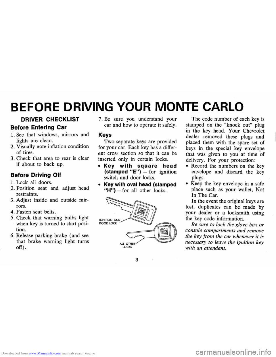
Keys
Two separate keys are provided
for your car. Each key has a differ
ent cross section so that it can be
inserted only
in certain locks.
• Key with square head
(stamped "E") -for ignition
switch and door locks.
• Key with oval head (stamped
"H") -for all other locks.
fib
~ ALL OTHER LOCKS
3
The code number of each key is
stamped on the "knock out" plug
in the key head. Your Chevrolet
dealer removed these plugs and
placed them with the spare set of
keys in the special key envelope
that was given to you at time of
delivery. For your protection:
• Record the numbers on the key
envelope and discard the key
plugs.
• Keep the key envelope in a safe
place such
as your wallet, Not
In The Car.
In the event the original keys are
lost, duplicates can be made by
your dealer or a locksmith using
the key code information.
Be sure to lock the glove box or
console compartments and remove
the key from the car whenever it
is
necessary to leave the ignition key
with an attendant.
Page 7 of 86
Downloaded from www.Manualslib.com manuals search engine to provide front seating conve
nience and easy entrance into the
rear seat area. To turn swivel seat,
depress control lever at outboard
side of seat base, then turn seat.
Position seat in forward
locked
position, prior to operating car.
Power Operated Front Seats-
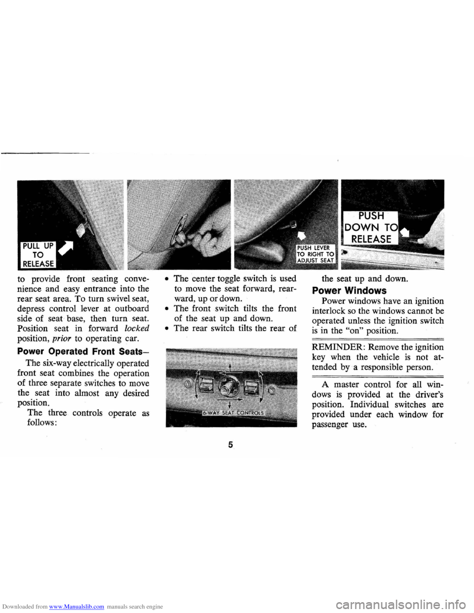
The six-way electrically operated
front seat combines the operation
of three separate switches to move
the seat into almost any desired
position.
The three controls operate
as
follows:
• The center toggle switch is used
to move the seat forward, rear
ward, up or down.
• The front switch tilts the front
of the seat up and down.
• The rear switch tilts the rear of
5
the seat up and down.
Power Windows
Power windows have an ignition
interlock so the windows cannot be
operated unless the ignition switch
is in the "on" position.
REMINDER: Remove the ignition
key when the vehicle
is not at
tended
bya responsible person.
A master control for all win
dows
is provided at the driver's
position. Individual switches are
provided under each window for
passenger use.
Page 10 of 86
Downloaded from www.Manualslib.com manuals search engine Seat Belt Buzzer/Light
Reminder
• The front outboard lap belts
(those next to side windows)
are linked to a buzzer and light
which remind occupants to
fas
ten seat belts.
• On cars with automatic trans
missions, or manual transmis
sions with steering column
mounted shift levers , the buzzer
and light are designed to come
on when the ignition switch
is
on, the transmission selector is
in a forward drive position, and
the driver's or right front pas
senger's lap belt
is not fastened.
• On manual transmission cars
with floor mounted shift controls
the reminders are designed to
come on when the ignition switch
is on, the driver's or right front
passenger's lap belt
is not fas
tened and the transmission
is in
any gear position, except that
NOTE: The right front seat con
tains a weight detector which
is de
signed to activate the buzzer and
light whenever a nominal weight
is placed on the seat. The weight
detector cannot distinguish be
tween a passenger and any item
of luggage or cargo, therefore such
items should be placed elsewhere
in the car, preferably
in the trunk.
they do not come on when
t~e
parking brake is engaged.
If seat belt system or reminder
system does not work
as described,
see your dealer for information
and assistance.
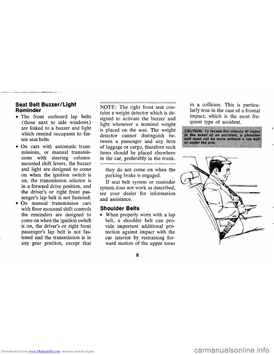
Shoulder Belts
• When properly worn with a lap
belt, a shoulder belt can pro
vide . important additional pro
tection against impact with the
car interior
by restraining for
ward motion of the upper torso
8
in a collision. This is particu
larly true in the case of a frontal
impact, which
is the most fre
quent type of accident.
Page 17 of 86
Downloaded from www.Manualslib.com manuals search engine STEERING COLUMN CONTROLS
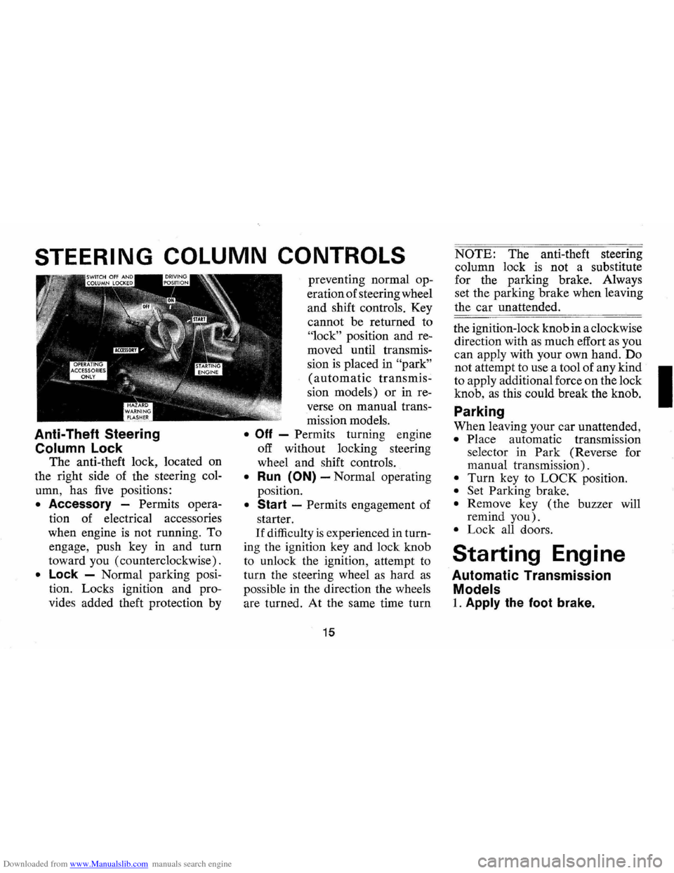
Anti-Theft Steering
Column Lock
The anti-theft lock, located on
the right side of the steering col
umn, has
five positions:
• Accessory -Permits opera
tion of electrical accessories
when engine
is not running. To
engage, push key in and turn
toward you (counterclockwise).
• Lock -Normal parking posi
tion. Locks ignition and pro
vides added theft protection by preventing
normal op
eration of steering wheel
and shift controls. Key
cannot be returned to
"lock" position and re
moved until transmis
sion
is placed in "park"
(automatic transmis
sion models) or in re
verse
on manual trans
mission models.
• Off - Permits turning engine
off without locking steering
wheel and shift controls.
• Run (ON) -Normal operating
position.
• Start -Permits engagement of
starter.
If difficulty is experienced in turn
ing the ignition key and lock knob
to unlock the ignition, attempt to
turn the steering wheel
as hard as
possible in the direction the wheels
are turned.
At the same time turn
15
NOTE: The anti-theft steering
column lock
is not a substitute
for the parking brake. Always
set the parking brake when leaving
the car unattended.
the ignition-lock knob in a clockwise
direction with
as much effort as you
can apply with your own hand.
Do
not attempt to use a tool of any kind I
to apply additional force on the lock
knob,
as this could break the knob.
Parking
When leaving your car unattended,
• Place automatic transmission
selector in
Park (Reverse for
manual transmission).
• Turn key to LOCK position.
• Set Parking brake.
• Remove key ( the buzzer will
remind
you).
• Lock all doors.
Starting Engine
Automatic Transmission
Models
1. Apply the foot brake.
Page 18 of 86
Downloaded from www.Manualslib.com manuals search engine 2. Place transmission selector
in uP" or uN" (UP" preferred).
A starter safety switch prevents
starter operation while the trans
mission selector
is in any drive
position.
(If it is necessary to
re-start the engine with the car
moving, place the selector lever
in
"N".)
3. Depress accelerator pedal and
activate starter
as outlined be
low for different conditions.
• Cold Engine -Fully de
press
accelerator pedal and
slowly release.
With foot off
the pedal, crank the engine
by turning the ignition key
to the Start position-release
when engine starts.
If engine starts, but fails to
run, repeat this procedure.
When engine is running
smoothly (approximately 30
seconds), the idle speed may
be reduced by slightly de- pressing
the accelerator pedal
and then slowly releasing.
• Warm Engine -Depress ac
celerator
pedal about halfway
and hold while cranking the
engine.
• Extremely Cold Weather
(Below 0° F.) Or After Car
Has Been Standing
Idle
Several
Oays-
Fully depress and release
accelerator pedal two or three
times before cranking the
engine.
With foot off the ac
celerator pedal,
crank the
engine by turning the key to
the Start position and release
when engine starts.
Manual Transmission Models
1. Apply parking brake and shift
16
transmission to neutral.
2.
Hold clutch pedal to floor
throughout the starting proce
dure.
A starter interlock pre
vents starter operation when
clutch
is not fully depressed.
(Select the proper gear position
before releasing the clutch pedal.)
3. Operate accelerator pedal and
starter
as outlined in step 3
(under Automatic Transmission
Models).
Engine Flooded
Depress accelerator pedal aJ;ld
hold to floor while starting until
engine
is cleared of excess fuel
and
is running smoothly. Never
"pump" the accelerator pedal.
Warm-Up
Always let the engine idle for
20 to 30 seconds after starting
and drive at moderate speeds for
several miles, especially during
cold weather.
Page 21 of 86
Downloaded from www.Manualslib.com manuals search engine Driving with Manual Transmissions
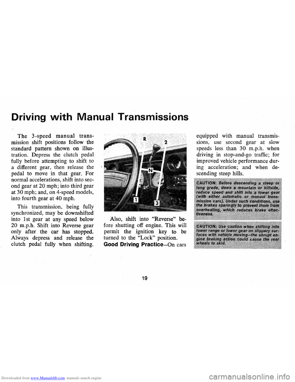
The 3-speed manual trans
mission shift positions follow the
standard pattern shown on illus
tration. Depress the clutch pedal
fully before attempting to shift
to
a different gear, then release the
pedal to move in that gear.
For
normal accelerations, shift into sec
ond gear at
20 mph; into third gear
at
30 mph; and, on 4-speed models,
into fourth gear at
40 mph.
This transmission, being fully
synchronized, may be downshifted
into 1 st gear
at any speed below
20 m.p.h. Shift into Reverse gear
only after the car has stopped.
Always depress and release the
clutch pedal fully when shifting. Also,
shift into
"Reverse" be
fore shutting
off engine. This will
permit the ignition key to be
turned to the
"Lock" position.
Good Driving Practice-On cars
19
equipped with manual transmis
sions, use second gear at slow
speed s less than
30 m.p .h. when
driving in stop-and-go traffic; for
improved vehicle performance dur
ing acceleration; and when de
s cending steep hills.
Page 22 of 86
Downloaded from www.Manualslib.com manuals search engine Turn Signal and Lane
. Change Features
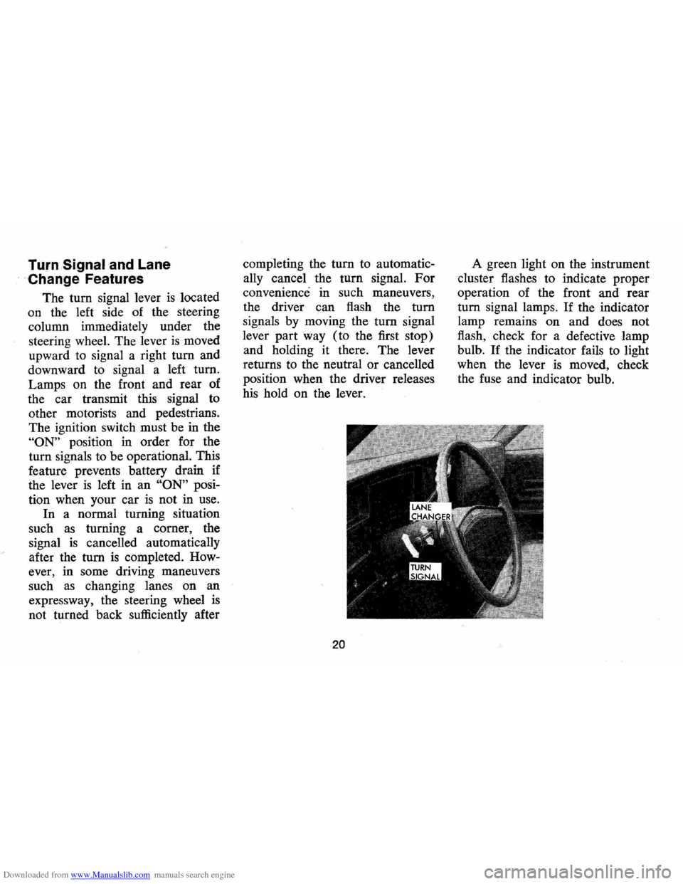
The tum signal lever is located
on the left side of the steering
column immediately under the
steering wheel. The lever
is moved
upward to signal a right
tum and
downward to signal a left tum.
Lamps on the front and rear of
the car transmit this signal to
other motorists and pedestrians.
The ignition switch must be in the
"ON" position in order for the
turn signals to be operational. This
feature prevents battery drain if
the lever
is left in an "ON" posi
tion when your car
is not in use.
In a normal turning situation
such
as turning a comer, the
signal
is cancelled automatically
after the tum
is completed. How
ever, in some driving maneuvers
such
as changing lanes on an
expressway, the steering wheel
is
not turned back sufficiently after completing
the
tum to automatic
ally cancel the turn signal.
For
convenience in such maneuvers,
the driver can flash the
tum
signals by moving the tum signal
lever part way (to the first stop)
and holding it there. The lever
returns to the neutral
or cancelled
position when the driver releases
his hold on the lever.
20
A green light on the instrument
cluster flashes to indicate proper
operation of the front and rear
tum signal lamps. If the indicator
lamp remains on and does not
flash, check for a defective lamp
bulb.
If the indicator fails to light
when the lever
is moved, check
the fuse and indicator bulb.
Page 25 of 86
Downloaded from www.Manualslib.com manuals search engine FLOOR CONTROLS
Braking System
The service brake system is de
signed for braking performance
under a wide range of driving con
ditions even when the vehicle
is
loaded to its full rated vehicle load.
Power Brakes
• On cars with power brakes if
power assist to the brakes
is
interrupted due to a stalled en
gine
or some malfunction, two
or more brake applications can
be made using reverse power.
• If the brake pedal is held down ,
the system
is designed to bring
the car to a full stop on reserve
power. However, the reserve
power
is partially depleted each
time the brake pedal
is applied
and released.
• When reserve power is ex- hausted,
the vehicle can still be
stopped by applying greater
force to the pedal.
Parking Brake
• To set parking brake, fully de
press foot pedal at far left side.
• For maximum holding power,
depress regular brake pedal with
the other foot at the same time.
• To release parking brake, pull
"BRAKE RELEASE" lever on
lower left instrument panel.
• As a reminder, the brake system
warning light
is designed to glow
whenever the parking brake con
trol
is not fully released, and the
ignition
is on.
• Never drive car with parking
brake set
as this may overheat
or otherwise damage rear brakes.
23
Clutch Adjustment
Clut8h adjustment should be
checked and adjusted periodically
as necessary to compensate for
clutch facing wear.
To check, de
press pedal by hand until resist
ance
is felt. Free travel of pedal
should be approximately one inch;
if very little
or no free travel is
evident, clutch adjustment is re
quired.
Page 28 of 86
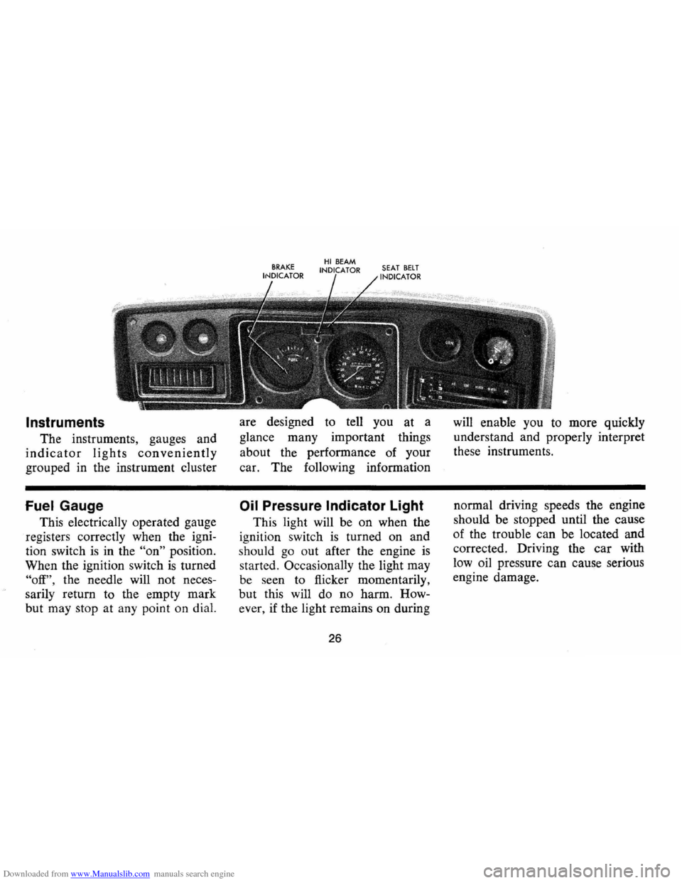
Downloaded from www.Manualslib.com manuals search engine Instruments
The instruments, gauges and
indicator lights conveniently
grouped in the instrument cluster
Fuel Gauge
This electrically operated gauge
registers correctly when the igni
tion switch
is in the "on" position.
When the ignition switch
is turned
"off", the needle will not neces
sarily return to the empty mark
but may stop at any point on dial. are
designed to tell you at a
glance many important things
about the performance of your
car. The foIlowing information
Oil Pressure Indicator Light
This light will be on when the
ignition switch
is turned on and
s hould
go out after the engine is
started. OccasionaIly the light may
be seen to flicker momentarily,
but this will do no harm. How
ever , if the light remains on during
26
will enable you to more quickly
understand and properly interpret
these instruments .
normal driving speeds the engine
should be stopped until the cause
of the trouble ca n be located and
corrected. Driving the
car with
low oil pressure can cause serious
engine damage.
Page 29 of 86
Downloaded from www.Manualslib.com manuals search engine Generator Indicator Light
This light provides a quick
check on the generating system
of your car. The red light will
go on when the ignition key
is
in the "on" position, but before
the engine
is started. After the
engine starts, the light should go
out and remain out.
If the light
remains on when engine
is run
ning , have your Authorized Chev
rolet Dealer locate and correct
the trouble
as soon as possible.
Engine Temperature
Indicator Light
This indicator light is provided
in the
instrument cluster to
quickly warn of an overheated
engine. With the ignition switch
in the
START position, the red
TEMP indicator will light to let
you know that it
is operating
properly. When the engine
is started, the red
light will go out immediately.
It will light up at no other time
unless for some reason the engine
reaches a dangerously high oper
ating temperature.
If the red light
should come on, the engine must
be stopped until the cause of the
overheating
is corrected. Glance
at instrument cluster frequently
as
you drive to see if this light is on.
Brake System Warning Light
The service brake system is
designed so that half of the brake
system will provide some braking
action in the event of a hydraulic
leak in the other half of the
sys
tem. If the warning light located
below the fuel gauge glows con
tinuously when the ignition
is on
and after the brakes have been
firmly applied, it may indicate that
there
is a malfunction in one half
of the brake hydraulic system.
27
• As a check on bulb condition
the light should glow with the
parking brake applied and the
ignition on. (Light
is also a
reminder to release parking
brake) .
• Have system repaired if light
does not come on during check.
• This warning light is not a sub
stitute for the visual check of
brake fluid level required
as
part of normal maintenance.
If the light glows red:
• The parking brake control is not
fully released or,
• The service brake system is
partially inoperative
What to do:
1. Check that the parking brake
is released. If it is ...
2. Pull off the road and stop,
carefully- remembering that: