check engine CHEVROLET MONTE CARLO 1981 4.G Owner's Manual
[x] Cancel search | Manufacturer: CHEVROLET, Model Year: 1981, Model line: MONTE CARLO, Model: CHEVROLET MONTE CARLO 1981 4.GPages: 104, PDF Size: 23.92 MB
Page 54 of 104
Downloaded from www.Manualslib.com manuals search engine • Always wear eye protection or shiekI your eyet when ,workmg .....,. My battery. Do not lean over a, battery. Remove .11 met.1 jewelry.
• Never expose .-battery to open fIanea eM' e~ sparb. -AlIa. do no( smoke near a battery.
• 00 not .llow battery acid to c:ontact eyes._IIdn. f~or painted autfaces. FLUSH ANY CONTACTED ARE"WlTH W"TER '_OtATELY AND THOIlOUGHLY. GET MEDICAL HELP IF EYES ARE AFFECTED.
• Be sure ' the Jumper cabie. or clampt to be used for jump starting do not have lOose or missing insulation. Do not prPCeed if $Uitable c.bae. .... not avanable. "
• Thi" vehicle has • 12-volt. batt.ry and a _ negative ground electrical .ystem. Make sure that -the other vehkte abo ha. a 12-vott battery .nd that tt .. the negative (~k II";"''') terminal which i. grounded (anached to the engine btoc:k). Hs owner's manual may give you that information. 00 NOT TRY TO JUMP START IF YOU ARE UNSURE OF THE OTHER VEHICLES VOl.TAGE ORGROOND (OR F THE OTHER VEHICLE'S VOLTAGE AND/OR Gr:tOUND ARE DIFFERENT FROM YOUR VEHICLE).
e. • eithel t'latIetY has flUer c:ap', check the flukt -leveL (Do _ no( cheek wlUl an open ta.M.> If lOw, flll'tO-ttle proper leVel with cia.,. drinking water. Replace aU c:aps before jump atarting.
e Do not allow metal tools to contact both the positive (red "+ ") battMy tennil\al (or any metal connected to thl. tenninal) and .ny other metal on either vehicle at the -same -tIme. ",.ke c:ertillin when .ftaching th6 Jumper c.~ elamps to the positive terminals Of the batteriet: _that neither clamp contacts. MY other metal •
• ' Alway. make the final ~o-"nectlon to' ground, (a adlid, .tatlon.ty, metallic object) on the engine at '~ast4SO 'millimeter. (18 Inches) from the battery.
Procedure ~~~i~._ 1. posill oW\he ·,verncJe with the good (cnarged) .!>allery so that the jumper cables will reach. Do not let th'1vehiclestouch ..
2. Turn off all elec .ltic motors, lights and accessories in both vehicles, except
the hazard flasher or any light~ need!ld for the work area. Turn ott the
ignition ,. apply the perkingbiilke' fi'rmly, and· shift the automatic
tr.ansmission to
"P"(Park) in both vehicles.
3. Jum~r Cable Connj!ction Instructions (See Illustration).
• Connecflhe
first jurnpercable to the positive " +" (red) terminal on
one battery, and. then to the positive" +" (red) terminal on the other
battery .
Never conlledt " +" (redl,to "-" (black), or "-" to " + ".
• Next, COnnect one endot theseC(jnd cable to the grounded negative "-"(black) terminal of the good (charged) battery.
• Lastly. c<;>nnect the other end· of the second jumP'l' cable to ground at least 450 millimeters (18 inches) from the discharged battery, to a solid, stationery, metallic object on the engine. Do not route the cable,
or
attach the clamp on or near pulleys, fans, or other parts that will
move when the engine is started , Be careful to noUouch hot engine
parts
as they can cause burns. The MOUNTING BRACKETS for the Delcotron (generator), or the ainlOnditioner compressor, generally
make a good point for this final ground attachment, ~ hot· or moving
parts c"" be avoided.
3-2
Page 56 of 104
Downloaded from www.Manualslib.com manuals search engine "the "TEMP" light comes on (or, if you have a 900lant temperature gage, the
gage needle goes into the warning zone) and your air conditioner is on, turn it
off.
If the "TEMP" light (or gage) comes on while you are stopped in traffic,
shift the transmission to
"N" (Neutral).
If the "TEMP" light doesn't go off (or the gage needle doesn't start to drop)
within a minute or two:
• Pull over to a safe Place ""d stop the vehicle. Set the parking brake and
shift to "P" (Park) 9r, with a manual transmission, shift to Neutral first, then
set the parking brake.
• DON'T TURN OFF THE ENGINE. INCREASE THE ENGINE SPEED until it
sounds like it's going about twice as fast as normal idle speed. Bring the
idle speed back to normal
after two or three minutes.
tfthe "TEMP" light still doesn't 90 off, (or the gage needle doesn't start to
drop),
NOW TURN OFF THE ENGINE and proceed as follows.
•
lift the engine hood. Look at the coolant level in the "see through" coolant
recovery tank. The coolant level. should be at or above the "Full Cold"
mark on the tank. If it looks like the coolant is boiling, wait until it stops
before proceeding. You should not need to remove the radiator cap to
check the coolant
level and. it can be dangerous if the coolant is still hot. See the following Caution.
CAUTION: To help avoid being burned:
"'-'''''''''i',",,;0-Fc:io'ffi)tcremoy'J~_ c;<)olant recovery tank cap if the coolant is boiling, and
• do not remove -the radiatorc:ap WhilethIit8ngine'-aUid:radiltor a,.Slili hot.
Scalding fluid and steamean be released under pressure it either cap is taken off too soon,
-;<
• If coolant level is low:
•
looklorleaks at the radiator hoses and connections, heater hoses and
connections,
r"diator,and water pump. See that the. fan belts are not
broken or off the pulleys an.d that the fan turns when the engine is started,
•
Add coolant to the recovery tahk.
If
the cQolant level in the recovery tank is althe correct lellel arid the "TEMP"
light (gage) still co"",s.dn,. air may be tr~ in the cooling system, This may
stop coolant from returning to the radiator. In this case, you may have to add
coolant directly to the radiator.
See "Coolant Replacement" under engine
cooling system
in "Service and Maintenance," Section 5 of this manual. Follow
steps 1 and 10. for the correct way to remove the radiator cap and add .coolant
to the radiator.
After the
"TEMP" light is out (or the gage needle is out of the warning zone),
resume driving at a reduced speed. Return to normal driving after about ten
minutes if the light does not come back
on (or the gage needle does not go
back into the warning zone).
3-4
Page 60 of 104
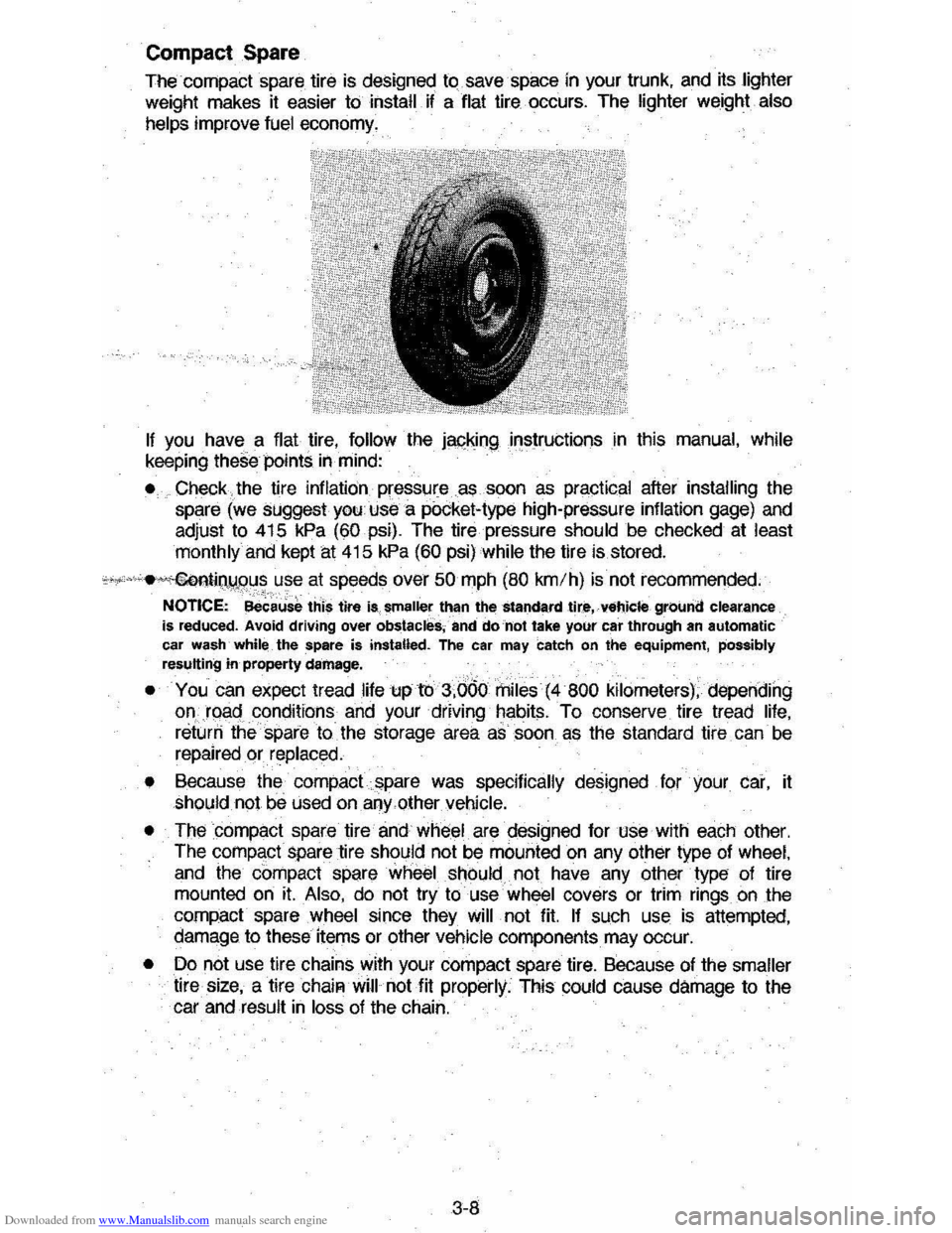
Downloaded from www.Manualslib.com manuals search engine Compact Spare
The-compact spare tire is designed to.save-space in your trunk, and its lighter
weight makes it easier to install if a flat tire occurs. The lighter weight also
helps
improve fuel economy.
If you have a flat tire, follow the japking .instructions in this manual, while keeping these points in mind:
• Check the tire inflation pressure as soon as practical after installing the
spare (we suggest you use a pOcket-type high-pressure inflation gage) and
adjust to 415
kPa (60 psi). The tire pressure should be checked at least
monthly and kept at 415 kPa (60 psi) while the tire is stored.
c"""'.M~llijIW.9u~ use at speeds over 50 mph (80 km/h) is not recommended.
NOTICE: -Bec~us~ this tire is, smaller than the standard tire,-vehicle ground clearance is reduced. Avoid driving over obstacles, -and do 'not take your car through an automatic car wash -while _ the spare is installed. The car may catch on the equipment, possibly resulting in property damage.
• You can expect tread ,life up to 3,660 rhiles(4800 kilometers), depending onJqact~ondi~ions and your driving ~~bits. To conserve tire tread life, returri the -spare to _ the storage area as soon as the standard tire _ can be
repaired or replaced.
•
Because the compact spare was specifically designed for your car, it should not be used on any.other vehicle.
• The
compact spare tire and wheel are cfesigned for use with each other.
The comp,,:ct spare tire should not be mounted on any other type of wheel,
and the compact spare wheel should not have any other type of tire mounted on it. Also, do not try to use wheel covers or trim rings on the
compact spare wheel since they will not fit. If such use is attempted,
damage to these items or other vehicle components may occur.
• Do not use tire chains with your compact spare tire. Because of the smaller
tire size, a tire ChaiR will not fit properly. This could cause damage to the car and result in loss of the chain.
3-8
Page 69 of 104
Downloaded from www.Manualslib.com manuals search engine SECTION 5
SERVICE AND MAINTENANCE
CAUTION: As with any mletdne, take car. when making any check, doing any maintenance, or making any repair, to avoid being Injured. Note that some of the materials in this vehicle may be hazardous if used, serviced , or handled improperly. Improper or incomplete servl'c. could alao lead to the vehicle ItMn not working properly which may resuH in personal Injury, or damage to the vehicle or its equipment. n you holy. any question about carrying out some service, hoIv. the service done by a skilled technician.
REPLACEMENT FASTENERS
During vehicle maintenance , any fasteners used to replace older ones must
h ,ave the same measurements and strength as those removed, whether metric or customary. (The numbers on the heads of metric bolts and on the surface s
of metric nuts show their strength . Customary
bolts use radial lines to show
thi s,
while most customa ry nuts do not have strength markings.) Fasteners
taken from the vehicle should be saved for re-use in the same spot when
possible . Where a fastener cannot be used again, take care to choo se a
repla cement that matches the old one. For information and help , see your dealer. .
CAUTION: This vehicle has some parts dimensioned in the metric system as well .. in the customary system. Some fasteners are metric and are very close in dimensnion to well· known customary fasteners in the inch system. Mismatched or incorrect fasteners
can result tnda~tp ~ vehic" or possibly personal Injury.
MAINTENANCE SCHEDULE AND WARRANTY
FOLDERS
For owner convenience, a separate folder has been provided with your vehicle which contains a complete maintenance schedule. It also briefly describes the
safety I emission control, lubrication and general service your vehicle requires.
The Maintenance Schedule folder is supplemented by this section of the
Owner 's
Manual.
Two Warranty Folders are also furnished with your Vehicle. These provide
detailed information on the :
• t981 Chevrolet New Vehicle Lim ited Warranty
• 1981 Chevrolet Perforation From Corrosion Limited Warranty
• 1981 Emissions Control Systems Warranties, including:
•
Emission Components Defect Warranty
• Emission Pertormance Warranty
• 1981 Chevrolet Powertrain Lirnited Warranty -Power Protection Plus
Read all four publications for a full understanding of your vehicle 's
maintenance needs.
You can get a replacement Maintenance Schedule from your dealer or send
the
VIN (or serial numbe r) of your vehicle to Consumer Relations, Chevrolet
Cent ral Office, Chevrolet Motor Division, Warren, Michigan 48090.
5-1
Page 71 of 104
Downloaded from www.Manualslib.com manuals search engine COMPUTER COMMAND CONTROL SYSTEM
Your new vehicle has a special emission contrOl system, called the Computer
Command Control system. Some vehicleS sold in Canada also have the
Computer Command Control system. II your Canadian vehicle has a "CHECK
ENGINE" light,
it dOes have the Computer Command Control system.)
The Computer Command Control system monitors . the .exhaust stream with
an
oxygen sensor. Based on sensor signals, the electronic control module adjusts
the carburetor air-fuel ratio as needed. It is very important to use only
unleaded gasoline in vehicles equipped with the Computer COmmand Control
system . .Leaded gasoline will damage the oxygen sensor and may affect
. emission controL .
On
all vehicles with the COmpute r Command Control system, a "CHECK
ENGINE" ligtit
on the instrument panel is designed to come on during engine
starting, to
let you knowthe bulb .is working. (The light will stay on a'shdl1iime
after the. engine starts.) If. the light comes on while driving, service to the
Computer Command Control system may be. required. Although your vehicle
may
still be drivable,see yoyr dealer as SOon as possible for an inspection of
the system.
Continued
driving · Without having the Computer Command Control system
serviced could cause damage to the emiSsion control system. It could also aftect fuel economy and drivability. .. ..
ENGINE OIL AND FILTER RECOMMENDATIONS
Checking 011 Level ,>,-.. ,
The engine oil must be kept at the right level to. help assure proper lubrication
of your vehicle' .s engine.
It is the owner's responsibility to' cheCk the oil level at
regular': infervals '{such . 'as . "e~~Y"JHflLstop), according ·to ' the following instruct ions . It is normal for an engine-O to use Some oil, and most engines may
use
more oil when they are new . " .
• The best time to check' the engine Orffevel is when the oil IS warm, such as
during a
fuel stop. First, wait about 5 minutes for the oil to drain back to the oil pan. Then, pull out the dipstick on the side of the engine block (either
right or left). Wipe
it clean and. push the dipstick back down all the way.
Now,
pull out the dipstick and look at the oil level .on the dipstick.
Some dipsticks have "Add" and "Full" lines. Others are marked "Add lOt"
and "OperatlngRange ." In all cases, keep the oil level above the "Add" line_ Push the dipstick .oock down alilheway after taking the reading . Add oil , if needed . . .
• If you check the oil level when the oil is cold, do not iun the engine first.
The
cold oil will not drain back to the pan fast enough to give a tr ue oil
level. . .
Ch '
oosing the Right Quality on
Engine oils are labeled on'the containers with variOus API (Amercian Petroleum Institute) deSignations of·quality. Artewhigher-quality category of engine 011,
designation "SF", was introduced early in 1980. Be sure the oil you use has
the
API designation "SF," either alone or shown with other designations . Do not use oils labeled only SA, SB,SC, SO,' SE, CA, CB,CC, or CD; or oils
with a combination of any of these categories-like SE/CD.
5-3
Page 73 of 104
Downloaded from www.Manualslib.com manuals search engine un mUE SAl: VIScOSITY GRADES
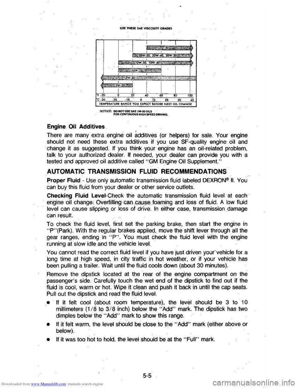
F~O 20 40 60 100 C -30 -20 10 0 10 20 30 40 TEMPERATURE RANGE YOU .EXPECT SHORE NEXT Oil CHANGE
NOTICe: DO NOTUSE SAE 5W-2(I OILS fOR COIfi"INUOUS HIGH SPEED DRIVING.
Engine Oil Additives
There are many extra engine oil additives (or helpers) for sale. Your engine
should not need these extra additives if you Use SF-quality engine oil and
change it as suggested. If you think your engine has an oil-related problem,
talk
to your authorized dealer. If needed, your dealer can provide you with a
tested and approved oil additive called "GM Engine Oil Supplement."
AUTOMATIC TRANSMISSION FLUID RECOMMENDATIONS
Proper Fluid -Use only automatic transmission fluid labeled DEXRON® II. You
can buy this fluid from your dealer or other service outlets.
Checking
Fluid Level-Check the automatic transmission fluid level at each
engine
oil change, Overfilling GaI).c"!,J~e foaming and loss of fluid. A low fluid
level can cause slipping or loss of drive. In either case, transmission damage
can result.
To check the fluid
level, first set the parking brake, then start the engine in "P"(Park). With the regular brakes applied, move the shift lever through all the
gear ranges, ending
in "P". You must check the fluid level with the engine
running
at slow idle and the vehicle level.
You cannot read the correct fluid level if you have just.driven you(vehicle fora
long time at high speed, in city traffic in hot weather, or if your vehicle has
been
pulling a trailer. Wait until the fluid cools down (about 30 minutes).
Remove the dipstick
located at the rear of the engine compartment on the
passenger's side. Carefully touch the wet end of the dipstick to find out if the
fluid
is cool, warm or hot. Wipe it clean and push it back in until the cap seats. Pull out the dipstick and read the fluid level.
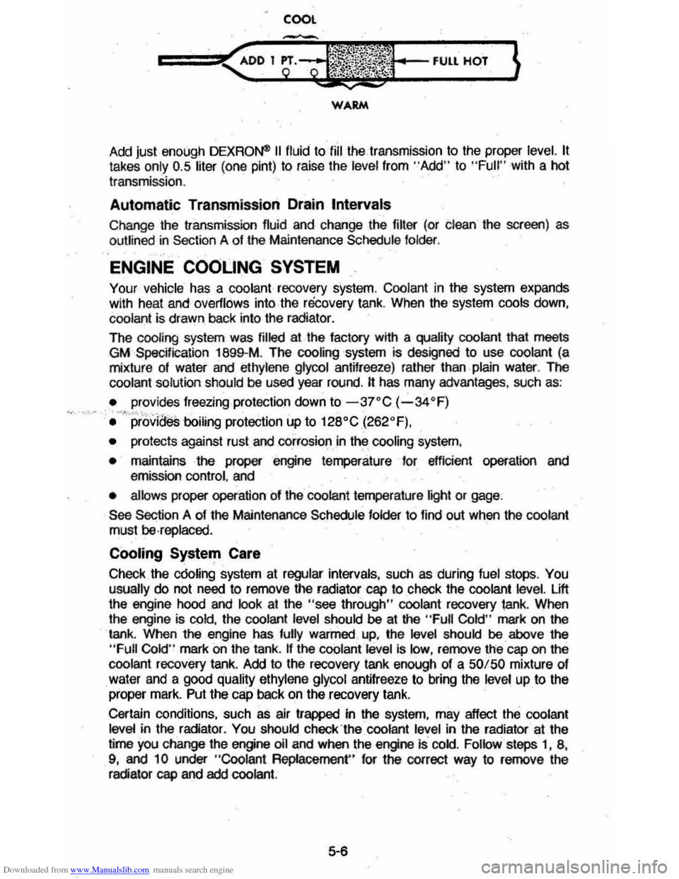
• If
it felt cool (about room temperature), the level should be 3 to 10
millimeters (118 to 3/8 inch) below the "Add" mark. The dipstick has two
dimples below the" Add" mark to show this range.
• If it felt warm, the level should be close to \he "Add" mark (either above or below).
• If
it was too hot to hold, the level should be at the "Full" mark.
5-5
Page 74 of 104
Downloaded from www.Manualslib.com manuals search engine COOL
WARM
Add just enough DEXRO~ II fluid to fill the transmission to the proper level. It
takes only 0.5 liter (one pint) to raise the level from "Add" to "Full" with a hot
transmission.
Automatic Transmission Drain Intervals
Change the transmission fluid and change the filter (or clean the screen) as
outlined
in Section A of the Maintenance Schedule folder.
ENGINE COOLING SYSTEM
Your vehicle has a coolant recovery system. Coolant in the system expands
with heat and overflows into the recovery tank. When the system cools down,
coolant is drawn back into the radiator.
The cooling system was
filled at the factory wrth a quality coolant that meets
GM
Spec~ication 1S99-M . The cooling ·system is designed to use coolant (a
mixture of water and ethylene glycol antifreeze) rather than plain water. The
coolant solution should be used year round.
It has many advantages, such as:
~ provides freezing protection down to -3rC (-34"F) "''''''<~. !'"","."" ' • provides boiling protection up to 12S"C (262"F),
• protects against rust and corrosio~in th~ cooling system,
• maintains the proper engine temperature for efficient operation and
emission control, and
• allows proper operation of the coolant temperature light or gage :
See Section A of the Maintenance Schedule folder to find out when the coolant
must
be ·replaced.
Cooling System Care
Check the c60ling system at regular intervals, such as during fuel stops . You usually do not need to remove the radiator cap to check the coolant level. Lift
the engine hood and look at the "see through" coolant recovery tank. When
the engine is
cold, the coolant level should be at the "Full Cold" mark on the
tank . When the engine has fully warmed . up, the level should be above the
"Full Cold" mark on the tank . If the coolantl6vel is low, remove the cap on the
coolant recovery tank. Add to the recovery tank enough of a 50/50 mixture of
water and a good quality ethylene glycol antifreeze to bring the
level up to the
proper mark. Put the cap back on the recovery tank.
Certain conditions, such
as air trapped in the system, may affect the coolant
level in the radiator. You should check"the coolant level in the radiator at the
time you change the engine
oil and when the engine Is cold. Follow.taps I, S,
9, and 10 under "Coolant Repfacement" for the correct way to remove the
radiator cap and add coolant.
5-6
Page 75 of 104
Downloaded from www.Manualslib.com manuals search engine If you have to add coolant more than four times a year (either to the recovery
tank or to the radiator), see your dealer for a cooling system check.
NOTICE: If you use the proper quality antifreeze, there is no· need to add extra inhihitorsor additiveswtlich claim to improve-the system. They may be harmful to the proper operation of the system.
Cooling' System Service
The cooling system should be serviced at the intervals specified in Section A of
the Maintenance Schedule folder as follows:
1. Wash the radiator cap and filler neck with clean water. See step 1 of "Coolant Replacement" for the proper way to remove the radiator cap.
2. Check the coolant level in the radiator and have it tested for freeze
protection.
Add ethylene glycol antifreeze, if needed, to maintain freeze
protection at-3JOC (~$4°f).
3. Have the cooling system and radiator cap tested for a pressure capacity of 105. kPa (15psi). (The pressure cantle anywhere from 95 kPa, or 14 psi,
to 120
kPa, or 18 psi.) If a replacement cap is needed, use an AC cap, or
an equivalent cap, designed fof coolant recovery systems and specffied for
your model.
4. Tighten all radiator hose clamps ang heater hose clamps and inspect all
hoses. Replace the hOSes if they are swollen, "checked" or otherwise worn.
NOTICE: Take care when tightening the hose clamps at the radiator. Overtightening could bend or collapse the radiator fittings.
5. Clean the front of the radiator core and air conditioning condenser to
remove dirt and other objects. Also clean the auxiliary engine oil andlor
transmission fluid cooler if the vehicle has them.
Coolant Replacernent
At the intervals specffied in Section A of the Maintenance Schedule folder, flush
9r1d refill the cooling system as follows:
1. Remove the radiator cap when the engine is cool:
•
Turn the cap slowly to the left until it reaches a "stop." Do not press
down while turning the
cap.
• Wait until any remaining pressure (indicated by a hissing sound) is
relieved, then press down on the cap and continue turning it to the left.
CAUTION: To help avoid the dangarm being burned. donotrem_ove the radiator cap While the engine' and radiator are. still. hot. Scaldingftukland steam ean be blown out under ~re It the cap is taken off too SOOf1.
2. When the cap is removed, run the engine until the upper rad.iator hose is
hot.
(ThiS shows that th~ thermostat is open and the coolant is flowing
through the system.)
3. Stop the engine. Open Ihe,actialor drain valVE! to drain the coolant. Drainage may be speeded by removing the drain plugs in the block, ff so
equipped.
5-7
Page 76 of 104
Downloaded from www.Manualslib.com manuals search engine 4. Close the drain valve. Install the block drain plugs, if removed. Add water
until the system is
filled and run the engine until the upper radiator hose is
hot
again.
5. Repeat steps 3 and 4 several times until the drained liquid is nearly colorless.
6. Drain the system, then close the radiator drain valve tightly. Install block
drain plugs, if removed.
7. Disconnect all hoses from the coolant recovery tank. Remove the recovery
tank
and pour out any fluid. Scrub and clean the inside of the recovery
tank with soap and water. Flush it well with clean water, then drain it.
Reinstall the recovery tank and hoses.
8. Add enough water and ethylene glycol antifreeze (meeting GM
Specification 1899-M) to provide the required cooling, freezing and
c()rrosion protection, Use a solution that is at least 50 percent antifreeze out no mOre than 70 percent antifreeze. Fill the radiator to the base of the
filler neck
and fill the coolant recovery tank to the "Full Hot" mark. Put the
recovery tank cap back on.
9. Run the engine, with the radiator cap removed, until the upper radiator
hose is hot.
10. With the engine idling, add coolant to the radiator until it reaches the
bottom of the filler neck. Install the radiator cap, making sure the arrows on the cap line up with the overflow tube.
iI is the owner's responsibility to,
'. -Main)!!!n cooling system freeze protection at -3rC (-34'F) to ensure protection against corrosion and loss of coolant from boiling. (A 50/50
mixture of water and ethylene glycol antifreeze will provide freeze
protection to -37'C or -34'F.) You should do this even if you don't
expect freezing temperatures.
• Add ethylene glycol base' antifreeze that meets GM Specification 1899-M
when antifreeze haS to be added because of coolant loss or for more
protection against freezing at temperatures lower than -37'C (-34'F).
NOTICE: Do "otute methanol-base antifreeze, Of alcohol,or plain water alone, in your vehicle at any time. They will boil at a lower point than that at which the "TEMP"
light (or temperature gage) will warn of overheating,. and they do not provide proper protection against cOrrosion.
Radiator Pressure Cap
The radiator cap, a 105 kPa (15 psi) pressure type, must be installed tightly,
otherwise coolant may be lost and damage to engine may result from
overheating. Radiator pressure
caps should be checked periodically for proper
operation. If replacement is required, an AC cap is recommended.
Thermostat
The engine coolant temperature is controlled by a thermostat. It stops coolant
flow
through the radiator until a preset temperature is reached. This thermostat
is installed in the engine
coolant outlet on the engine block. The same thermostat is used in both winter and summer. When a replacement is needed, AC"Delco parts are recommended.
5-8
Page 77 of 104
Downloaded from www.Manualslib.com manuals search engine Rear Axle, Standard
See Section A of the Maintenance Schedule folder to find out how often the
lubricant level should be checked. If you pull a trailer, the lubricant must be changed as recommended in the Maintenance.Schedule folder.
Add lubricant, if needed, to fill to the level of the filler plug hole on the
passenger's side of the
differential case. Use SAE BOW GL-S or SAE BOW·90
GL-S gear lubricant. (For those vehicles driven in Canada, use SAE BOW GL-S gear lubricant.) You can also use special gear lubricant Part No. GM 10S2271
or 10S2272. You can buy these products from your dealer.
Rear Axle--!-imited-Slip Differential
See Section A of the Maintenance Schedule folder to find out when the lubricant should be drained and refilled.
Refill to the level of the filler plug hole with special gear lubricant part No. GM
1052271 or 10S2272. You can buy these products from your authorized dealer.
Power Steering System
Check the fluid level in the power steering pump as recommended in the
Maintenance Schedule folder.
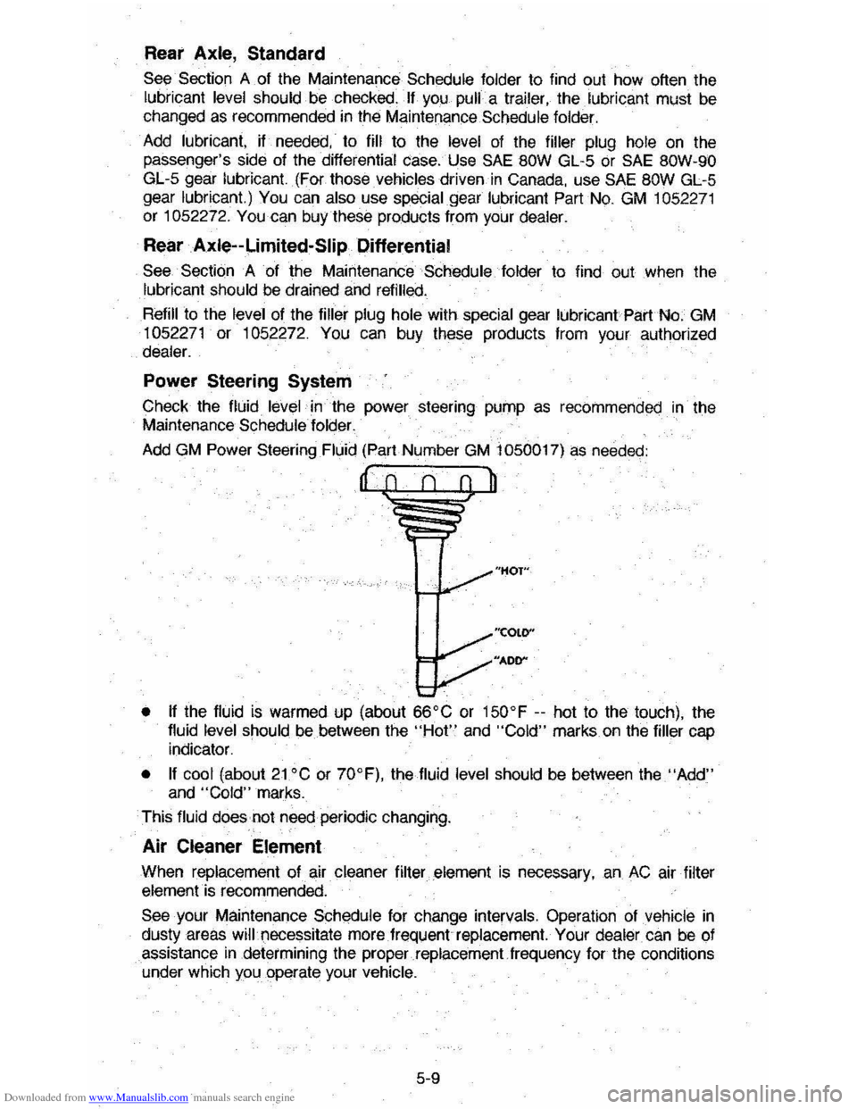
Add GM Power Steering Fluid (Part Number GM 1 OSOOI7) as needed:
"HOT"
"COLO"
"ADD"'"
• If the fluid is warmed up (about 66'C or IS0'F --hot to the touch), the
fluid level should be between the "Hot" and "Cold" marks on the filler cap
indicator.
• If cool (about 21 'C or 70'F), the fluid level should be between the "Add" and "Cold" marks.
This
fluid does not need periodic changing.
Air Cleaner Element
When replacement afair cleaner filter.;element is necessary. an AC air filter element is recommended.
See your Maintenance Schedule for change intervals. Operation of vehicle in
dusty areas will',necessitate more.frequentreplacernent.' Your dealer. can be of
assistance in determining the properreplacement.frequency for the conditions under which you operate your vehicle.
S-9