CHEVROLET PLYMOUTH ACCLAIM 1993 Service Manual
Manufacturer: CHEVROLET, Model Year: 1993, Model line: PLYMOUTH ACCLAIM, Model: CHEVROLET PLYMOUTH ACCLAIM 1993Pages: 2438, PDF Size: 74.98 MB
Page 1461 of 2438
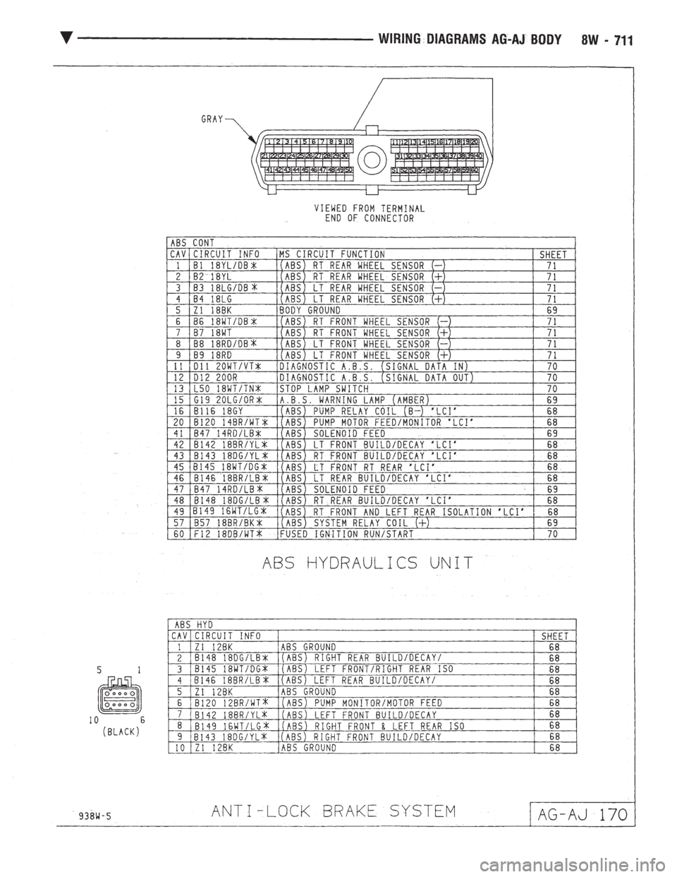
Page 1462 of 2438
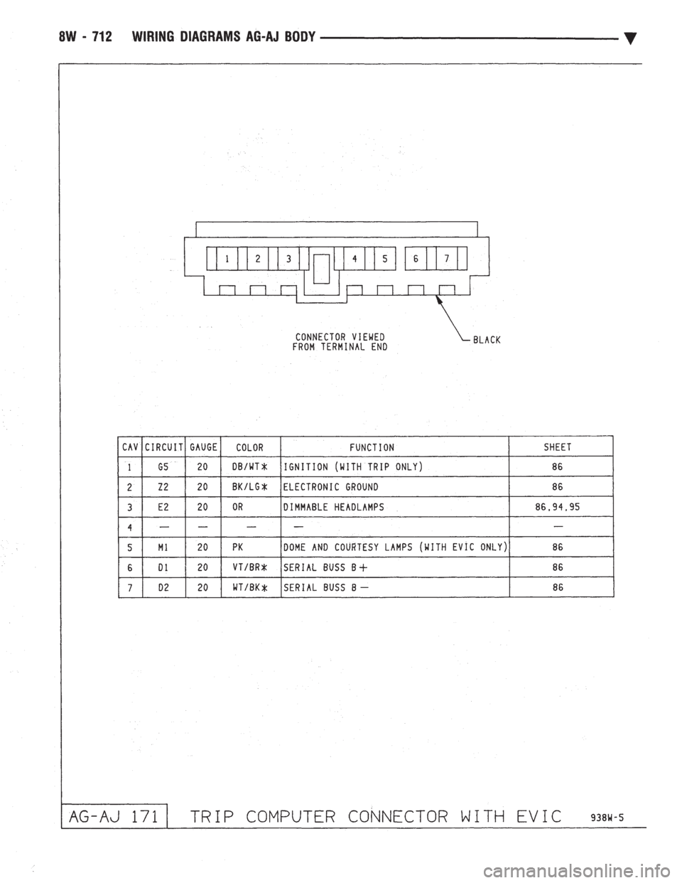
Page 1463 of 2438
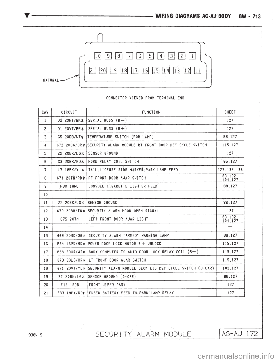
Page 1464 of 2438
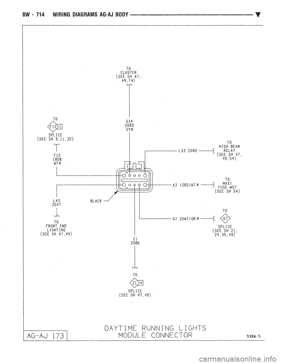
Page 1465 of 2438
Page 1466 of 2438

8W - 716 WIRING DIAGRAMS AP BODY D-P Ä
Page 1467 of 2438
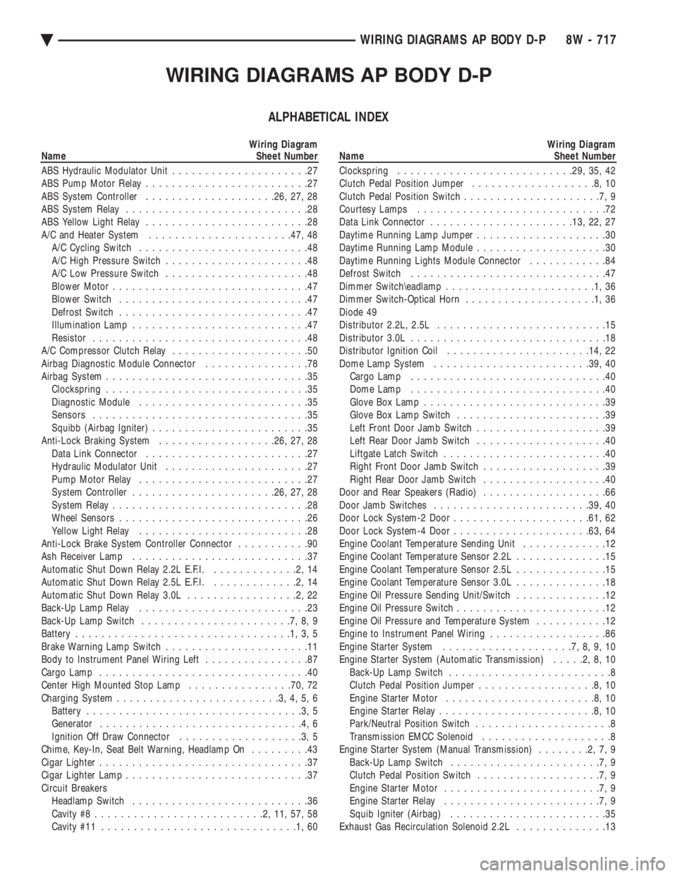
WIRING DIAGRAMS AP BODY D-P
ALPHABETICAL INDEX
Wiring Diagram
Name Sheet Number
ABS Hydraulic Modulator Unit .....................27
ABS Pump Motor Relay .........................27
ABS System Controller ................... .26, 27, 28
ABS System Relay ............................28
ABS Yellow Light Relay .........................28
A/C and Heater System ..................... .47, 48
A/C Cycling Switch ..........................48
A/C High Pressure Switch ......................48
A/C Low Pressure Switch ......................48
Blower Motor ..............................47
Blower Switch .............................47
Defrost Switch .............................47
Illumination Lamp ...........................47
Resistor .................................48
A/C Compressor Clutch Relay .....................50
Airbag Diagnostic Module Connector ................78
Airbag System ...............................35
Clockspring ...............................35
Diagnostic Module ..........................35
Sensors .................................35
Squibb (Airbag Igniter) ........................35
Anti-Lock Braking System ..................26, 27, 28
Data Link Connector .........................27
Hydraulic Modulator Unit ......................27
Pump Motor Relay ..........................27
System Controller ..................... .26, 27, 28
System Relay ..............................28
Wheel Sensors .............................26
Yellow Light Relay ..........................28
Anti-Lock Brake System Controller Connector ...........90
Ash Receiver Lamp ...........................37
Automatic Shut Down Relay 2.2L E.F.I. .............2,14
Automatic Shut Down Relay 2.5L E.F.I. .............2,14
Automatic Shut Down Relay 3.0L .................2,22
Back-Up Lamp Relay ..........................23
Back-Up Lamp Switch .......................7,8,9
Battery .................................1,3,5
Brake Warning Lamp Switch ......................11
Body to Instrument Panel Wiring Left ................87
Cargo Lamp ................................40
Center High Mounted Stop Lamp ................70, 72
Charging System .........................3,4,5,6
Battery .................................3,5
Generator ...............................4,6
Ignition Off Draw Connector ...................3,5
Chime, Key-In, Seat Belt Warning, Headlamp On .........43
Cigar Lighter ................................37
Cigar Lighter Lamp ............................37
Circuit Breakers Headlamp Switch ...........................36
Cavity #8 ..........................2,11,57,58
Cavity #11 ..............................1,60Wiring Diagram
Name Sheet Number
Clockspring .......................... .29, 35, 42
Clutch Pedal Position Jumper ...................8,10
Clutch Pedal Position Switch .....................7,9
Courtesy Lamps .............................72
Data Link Connector ..................... .13, 22, 27
Daytime Running Lamp Jumper ....................30
Daytime Running Lamp Module ....................30
Daytime Running Lights Module Connector ............84
Defrost Switch ..............................47
Dimmer Switch\eadlamp .......................1,36
Dimmer Switch-Optical Horn ....................1,36
Diode 49
Distributor 2.2L, 2.5L ..........................15
Distributor 3.0L ..............................18
Distributor Ignition Coil ..................... .14, 22
Dome Lamp System ....................... .39, 40
Cargo Lamp ..............................40
Dome Lamp ..............................40
Glove Box Lamp ............................39
Glove Box Lamp Switch .......................39
Left Front Door Jamb Switch ....................39
Left Rear Door Jamb Switch ....................40
Liftgate Latch Switch .........................40
Right Front Door Jamb Switch ...................39
Right Rear Door Jamb Switch ...................40
Door and Rear Speakers (Radio) ...................66
Door Jamb Switches ....................... .39, 40
Door Lock System-2 Door .................... .61, 62
Door Lock System-4 Door .................... .63, 64
Engine Coolant Temperature Sending Unit .............12
Engine Coolant Temperature Sensor 2.2L ..............15
Engine Coolant Temperature Sensor 2.5L ..............15
Engine Coolant Temperature Sensor 3.0L ..............18
Engine Oil Pressure Sending Unit/Switch ..............12
Engine Oil Pressure Switch .......................12
Engine Oil Pressure and Temperature System ...........12
Engine to Instrument Panel Wiring ..................86
Engine Starter System ....................7,8,9,10
Engine Starter System (Automatic Transmission) .....2,8,10
Back-Up Lamp Switch .........................8
Clutch Pedal Position Jumper ..................8,10
Engine Starter Motor .......................8,10
Engine Starter Relay ........................8,10
Park/Neutral Position Switch .....................8
Transmission EMCC Solenoid ....................8
Engine Starter System (Manual Transmission) ........2,7,9
Back-Up Lamp Switch .......................7,9
Clutch Pedal Position Switch ...................7,9
Engine Starter Motor ........................7,9
Engine Starter Relay ........................7,9
Squib Igniter (Airbag) ........................35
Exhaust Gas Recirculation Solenoid 2.2L ..............13
Ä WIRING DIAGRAMS AP BODY D-P 8W - 717
Page 1468 of 2438
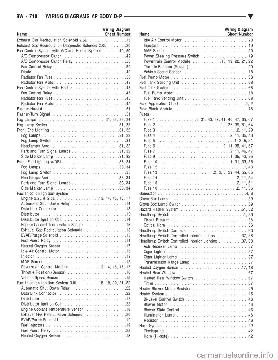
Wiring Diagram
Name Sheet Number
Exhaust Gas Recirculation Solenoid 2.5L ..............13
Exhaust Gas Recirculation Diagnostic Solenoid 3.0L. ......20
Fan Control System with A/C and Heater System ......49, 50
A/C Compressor Clutch .......................49
A/C Compressor Clutch Relay ...................50
Fan Control Relay ...........................50
Diode ...................................49
Radiator Fan Fuse ...........................50
Radiator Fan Motor ..........................49
Fan Control System with Heater ....................45
Fan Control Relay ...........................45
Radiator Fan Fuse ...........................45
Radiator Fan Motor ..........................45
Flasher-Hazard ..............................51
Flasher-Turn Signal ............................51
Fog Lamps ........................ .31, 32, 33, 34
Fog Lamp Switch ......................... .31, 33
Front End Lighting ........................ .31, 32
Fog Lamps ............................ .31, 32
Fog Lamp Switch ...........................31
Headlamps-Aero ........................ .31, 32
Park and Turn Signal Lamps ..................31, 32
Side Marker Lamp ....................... .31, 32
Front End Lighting w/DRL .................... .33, 34
Fog Lamps ............................ .33, 34
Fog Lamp Switch ...........................33
Headlamps-Aero ........................ .33, 34
Park and Turn Signal Lamps ..................33, 34
Side Marker Lamp ....................... .33, 34
Fuel Injection Ignition System Engine 2.2L & 2.5L ............... .13, 14, 15, 16, 17
Automatic Shut Down Relay ....................14
Data Link Connector .........................13
Distributor ...............................15
Distributor Ignition Coil .......................14
Engine Coolant Temperature Sensor ...............15
Exhaust Gas Recirculation Solenoid ................13
EVAP/Purge Solenoid .........................13
Fuel Pump Relay ...........................14
Heated Oxygen Sensor ........................17
Idle Air Control Motor ........................16
Injector .................................13
MAP Sensor ..............................15
Powertrain Control Module ...........13, 14, 15, 16, 17
Throttle Position (Sensor) ......................16
Vehicle Speed Sensor ........................15
Fuel Injection Ignition System 3.0L ........18, 19, 20, 21, 22
Automatic Shut Down Relay ....................22
Data Link Connector .........................22
Distributor ...............................18
Distributor Ignition Coil .......................22
Engine Coolant Temperature Sensor ...............18
Exhaust Gas Recirculation Solenoid ................20
EVAP/Purge Solenoid .........................19
Fuel Injectors ..............................19
Fuel Pump Relay ...........................22
Heated Oxygen Sensor ........................18Wiring Diagram
Name Sheet Number
Idle Air Control Motor ........................20
Injectors .................................19
MAP Sensor ..............................20
Power Steering Pressure Switch ..................19
Powertrain Control Module ...........18, 19, 20, 21, 22
Throttle Position (Sensor) ......................20
Vehicle Speed Sensor ........................18
Fuel Pump Motor .............................68
Fuel Tank Sending Unit .........................68
Fuel Tank System .............................68
Fuel Pump Motor ...........................58
Fuel Tank Sending Unit ........................68
Fuse Application Char t.........................1,2
Fuse Block Module ............................76
Fuses Fuse 1 ...............1,31,33,37,41,46,47,65,67
Fuse 2 ........................1,,36,39,61,64
Fuse 3 ..............................2,11,29
Fuse 4 ...........................2,11,35,43
Fuse 5 .............................1,3,5,51
Fuse 6 .........................2,11,35,41,67
Fuse 7 ...........................2,11,46,47
Fuse 9 ...........................1,35,42,65
Fuse 10 ..........................1,31,33,36
Fuse 12 ...............................1,43
Fuse 13 ....................2,3,5,39,44,55,65
Fuse 14 .............................2,11,54
Fuse 15 .............................2,11,51
Fuse 16 .............................2,11,65
Generator .................................4,6
Glove Box Lamp .............................39
Glove Box Lamp Switch .........................39
Hazard Flasher System ...................... .51, 52
Headlamp Switch ...........................1,36
Circuit Breaker .............................36
Optical Horn ..............................36
Headlamp Switch Connector ......................83
Headlamp Switch Controlled Interior Lamps .........37, 38
Headlamp Switch Controlled Interior Lighting .........37, 38
Ash Receiver Lamp ..........................37
Cigar Lighter ..............................37
Cigar Lighter Lamp ..........................37
Transmission Range Lamp .....................37
Heated Oxygen Sensor ...................... .17, 18
Heated Rear Window ..........................67
Heated Rear Window Switch ....................67
Timer ...................................67
Heater Blower Motor Resistor .....................46
Heater System ...............................46
Bi-Level Control Switch .......................46
Blower Motor ..............................46
Blower Slide Control .........................46
Illumination Lamp ...........................46
Resistor .................................46
Horn System ...............................42
Clockspring ...............................42
Horn (Hi-note) .............................42
8W - 718 WIRING DIAGRAMS AP BODY D-P Ä
Page 1469 of 2438
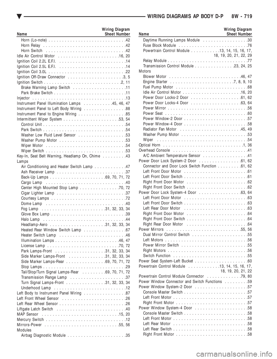
Wiring Diagram
Name Sheet Number
Horn (Lo-note) .............................42
Horn Relay ...............................42
Horn Switch ..............................42
Idle Air Control Motor ...................... .16, 20
Ignition Coil 2.2L E.F.I. .........................14
Ignition Coil 2.5L E.F.I. .........................14
Ignition Coil 3.0L .............................22
Ignition Off-Draw Connector .....................3,5
Ignition Switch .............................2,11
Brake Warning Lamp Switch ....................11
Park Brake Switch ...........................11
Injector ...................................13
Instrument Panel Illumination Lamps ...........45, 46, 47
Instrument Panel to Left Body Wiring ................88
Instrument Panel to Engine Wiring ..................85
Intermittent Wiper System .................... .53, 54
Control Unit ...............................54
Park Switch ...............................54
Washer Low Fluid Level Sensor ..................53
Washer Pump Motor .........................53
Wiper Motor ..............................54
Wiper Switch ..............................53
Key-In, Seat Belt Warning, Headlamp On, Chime .........43
Lamps Air Conditioning and Heater Switch Lamp ............47
Ash Receiver Lamp ..........................37
Back-Up Lamps .................... .69, 70, 71, 72
Cargo Lamp ..............................40
Center High Mounted Stop Lamp ...............70, 72
Cigar Lighter Lamp ..........................37
Courtesy Lamps ............................72
Dome Lamp ..............................40
Fog Lamp ....................... .31, 32, 33, 34
Glove Box Lamp ............................39
Halo Lamp ...............................44
Headlamp-Aero .................... .31, 32, 33, 34
Heated Rear Window Switch Lamp ................67
Heater Switch Lamp .........................46
Illumination Lamps ....................... .46, 47
License Lamp .......................... .70, 72
Park Lamps-Front .................. .31, 32, 33, 34
Side Marker Lamps-Front ..............31, 32, 33, 34
Side Marker Lamps-Rear ...............69, 70, 71, 72
Stop Lamps ...............................29
Tail/Stop/Turn Signal Lamps-Rear .........69, 70, 71, 72
Transmission Range Lamp .....................37
Turn Signal Lamps-Front ...............31, 32, 33, 34
Underhood Lamp ...........................12
Left Body to Instrument Panel Wiring ................87
Left Front Wheel Sensor ........................26
Left Rear Wheel Sensor .........................26
Liftgate Latch Switch ..........................40
MAP Sensor ............................ .15, 20
Mercury Switch ..............................12
Mirrors-Power ........................... .55, 56
Modules Airbag Diagnostic Module ......................35Wiring Diagram
Name Sheet Number
Daytime Running Lamps Module .................30
Fuse Block Module ..........................76
Powertrain Control Module ...........13, 14, 15, 16, 17,
18, 19, 20, 21, 22, 29
Relay Module ..............................77
Transmission Control Module ...............23, 24, 25
Motors Blower Motor .......................... .46, 47
Engine Starter ........................7,8,9,10
Fuel Pump Motor ...........................68
Idle Air Control Motor ..................... .16, 20
Power Door Locks-2 Door .................. .61, 62
Power Door Locks-4 Door .................. .63, 64
Power Mirror ..............................56
Power Seat ...............................60
Power Window-2 Door ........................57
Power Window-4 Door ........................58
Radiator Fan Motor ...................... .45, 49
Washer Pump Motor .........................53
Wiper ..................................54
Optical Horn ..............................1,36
Overhead Console ............................41
A/C Ambient Temperature Sensor .................41
Power Door Lock System-2 Door ................61, 62
Connector and Door Lock Switch Function .........61, 62
Left Front Door Motor ........................61
Left Front Door Switch ........................61
Right Front Door Motor .......................62
Right Front Door Switch .......................62
Power Door Lock System-4 Door ................63, 64
Left Front Door Motor ........................63
Left Front Door Switch ........................63
Left Rear Door Motor ........................63
Right Front Door Motor .......................64
Right Front Door Switch .......................64
Right Rear Door Motor .......................64
Power Mirrors ........................... .55, 56
Dual Mirror Control Switch .....................55
Left Motors ...............................56
Power Mirror Switch .........................55
Right Motors ..............................56
Switch Function ............................55
Power Seat System-Left Bucket ....................60
Powertrain Control Module ............13, 14, 15, 16, 17,
18, 19, 20, 21, 22
Powertrain Control Module Connector .............79, 80
Power Window Connector and Switch Functions .........59
Power Window System-2 Door ....................57
Console Master Switch ........................57
Left Front Motor ............................57
Right Front Motor ...........................57
Power Window System-4 Door ....................58
Console Master Switch ........................58
Left Front Motor ............................58
Left Rear Motor ............................58
Left Rear Switch ............................58
Right Front Motor ...........................58
Ä WIRING DIAGRAMS AP BODY D-P 8W - 719
Page 1470 of 2438
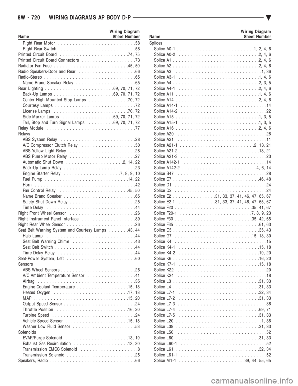
Wiring Diagram
Name Sheet Number
Right Rear Motor ...........................58
Right Rear Switch ...........................58
Printed Circuit Board ....................... .74, 75
Printed Circuit Board Connectors ...................73
Radiator Fan Fuse ......................... .45, 50
Radio Speakers-Door and Rear ....................66
Radio-Stereo ................................65
Name Brand Speaker Relay .....................65
Rear Lighting ....................... .69, 70, 71, 72
Back-Up Lamps .................... .69, 70, 71, 72
Center High Mounted Stop Lamps ..............70, 72
Courtesy Lamps ............................72
License Lamps ......................... .70, 72
Side Marker Lamps ................. .69, 70, 71, 72
Tail, Stop and Turn Signal Lamps .........69, 70, 71, 72
Relay Module ...............................77
Relays ABS System Relay ..........................28
A/C Compressor Clutch Relay ...................50
ABS Yellow Light Relay .......................28
ABS Pump Motor Relay .......................27
Automatic Shut Down ....................2,14,22
Back-Up Lamp Relay .........................23
Engine Starter Relay ....................7,8,9,10
Fuel Pump ............................ .14, 22
Horn ...................................42
Fan Control Relay ....................... .45, 50
Name Brand Speaker .........................65
Safety Shut Down Relay .......................25
Time Delay ...............................44
Right Front Wheel Sensor .......................26
Right Instrument Panel Interface ...................89
Right Rear Wheel Sensor ........................26
Seat Belt Warning System and Courtesy Lamps .......43, 44
Halo Lamp ...............................44
Seat Belt Warning Chime ......................43
Seat Belt Switch ............................44
Time Delay Relay ...........................44
Seat-Power System, Left ........................60
Sensors ABS Wheel Sensors ..........................26
A/C Ambient Temperature Sensor .................41
Airbag ..................................35
Engine Coolant Temperature ..................15, 18
Heated Oxygen ......................... .17, 18
MAP ................................ .15, 20
Output Speed Sensor .........................24
Throttle Position ........................ .16, 20
Turbine Speed .............................24
Vehicle Speed Sensor ..................... .15, 18
Washer Low Fluid Sensor ......................53
Solenoids EVAP/Purge Solenoid ..................... .13, 19
Exhaust Gas Recirculation .................. .13, 20
Transmission EMCC Solenoid ....................8
Transmission Solenoid ........................25
Speakers, Radio ..............................66Wiring Diagram
Name Sheet Number
Splices Splice A0-1 ...........................1,2,4,6
Splice A0-2 ............................2,4,6
Splice A1 ..............................2,4,6
Splice A2 ..............................2,4,6
Splice A3 ..............................1,36
Splice A3-1 ............................1,4,6
Splice A4 ..............................2,3,5
Splice A4-1 ............................2,4,6
Splice A11 .............................1,4,6
Splice A14 .............................2,4,6
Splice A14-1 ..............................14
Splice A14-2 ..............................22
Splice A15 .............................1,3,5
Splice A15-1 ...........................1,3,5
Splice A16 .............................2,4,6
Splice A20 ...............................28
Splice A21 ...............................11
Splice A21-1 ..........................2,13,21
Splice A21-2 ........................... .13, 21
Splice A21-3 ..............................23
Splice A142-1 .............................14
Splice A142-2 ..........................4,6,14
Splice B47 ...............................28
Splice C7 ............................. .46, 48
Splice D1 ................................24
Splice D2 ................................24
Splice E2 .............. .31, 33, 37, 41, 46, 47, 65, 67
Splice E2-1 ............ .31, 33, 37, 41, 46, 47, 65, 67
Splice F20 .......................... .35, 41, 67
Splice F20-1 .........................7,8,9,23
Splice F30 .......................... .35, 42, 65
Splice F35 ............................ .61, 63
Splice G5 ............................. .35, 43
Splice G7 .......................... .15, 18, 30
Splice K4 ................................15
Splice K4-1 ........................... .15, 18
Splice K4-2 ........................... .19, 20
Splice K6 ............................. .16, 20
Splice K7-1 ........................... .15, 18
Splice K22 ...............................20
Splice K24 ...............................18
Splice L3 ............................. .31, 33
Splice L4 ............................. .31, 33
Splice L7-1 ........................... .32, 34
Splice L7-2 ........................... .31, 33
Splice L7-3 ...............................36
Splice L7-4 ........................... .69, 71
Splice L7-5 ........................... .31, 33
Splice L20 ..............................1,36
Splice L39 ............................ .31, 33
Splice L50 ...............................52
Splice L60 ............................ .31, 33
Splice L60-1 ..............................52
Splice L61 ............................ .32, 34
Splice L61-1 ..............................52
Splice M1-1 ...................... .39, 44, 55, 65
8W - 720 WIRING DIAGRAMS AP BODY D-P Ä