brake fluid CHEVROLET PLYMOUTH ACCLAIM 1993 User Guide
[x] Cancel search | Manufacturer: CHEVROLET, Model Year: 1993, Model line: PLYMOUTH ACCLAIM, Model: CHEVROLET PLYMOUTH ACCLAIM 1993Pages: 2438, PDF Size: 74.98 MB
Page 156 of 2438
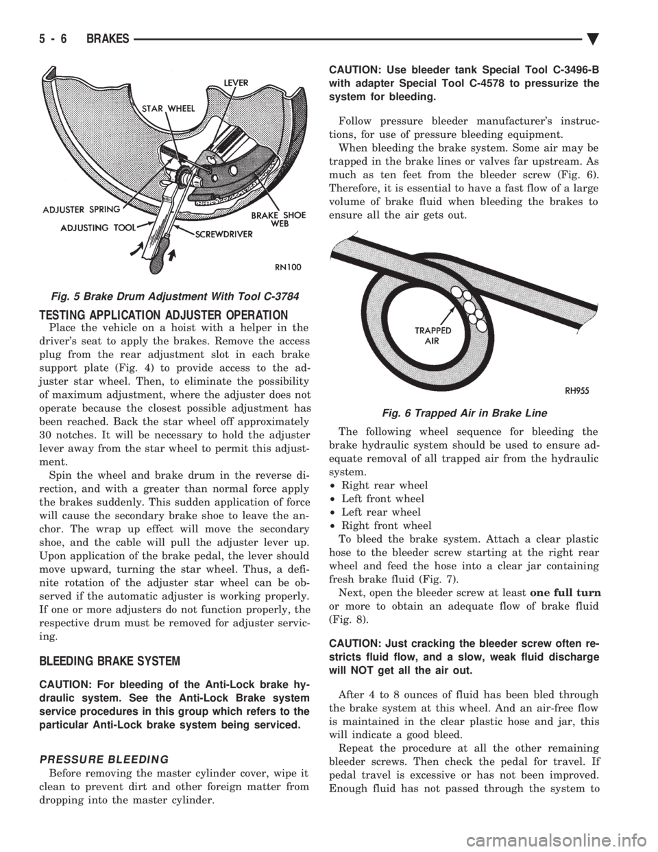
TESTING APPLICATION ADJUSTER OPERATION
Place the vehicle on a hoist with a helper in the
driver's seat to apply the brakes. Remove the access
plug from the rear adjustment slot in each brake
support plate (Fig. 4) to provide access to the ad-
juster star wheel. Then, to eliminate the possibility
of maximum adjustment, where the adjuster does not
operate because the closest possible adjustment has
been reached. Back the star wheel off approximately
30 notches. It will be necessary to hold the adjuster
lever away from the star wheel to permit this adjust-
ment. Spin the wheel and brake drum in the reverse di-
rection, and with a greater than normal force apply
the brakes suddenly. This sudden application of force
will cause the secondary brake shoe to leave the an-
chor. The wrap up effect will move the secondary
shoe, and the cable will pull the adjuster lever up.
Upon application of the brake pedal, the lever should
move upward, turning the star wheel. Thus, a defi-
nite rotation of the adjuster star wheel can be ob-
served if the automatic adjuster is working properly.
If one or more adjusters do not function properly, the
respective drum must be removed for adjuster servic-
ing.
BLEEDING BRAKE SYSTEM
CAUTION: For bleeding of the Anti-Lock brake hy-
draulic system. See the Anti-Lock Brake system
service procedures in this group which refers to the
particular Anti-Lock brake system being serviced.
PRESSURE BLEEDING
Before removing the master cylinder cover, wipe it
clean to prevent dirt and other foreign matter from
dropping into the master cylinder. CAUTION: Use bleeder tank Special Tool C-3496-B
with adapter Special Tool C-4578 to pressurize the
system for bleeding.
Follow pressure bleeder manufacturer's instruc-
tions, for use of pressure bleeding equipment. When bleeding the brake system. Some air may be
trapped in the brake lines or valves far upstream. As
much as ten feet from the bleeder screw (Fig. 6).
Therefore, it is essential to have a fast flow of a large
volume of brake fluid when bleeding the brakes to
ensure all the air gets out.
The following wheel sequence for bleeding the
brake hydraulic system should be used to ensure ad-
equate removal of all trapped air from the hydraulic
system.
² Right rear wheel
² Left front wheel
² Left rear wheel
² Right front wheel
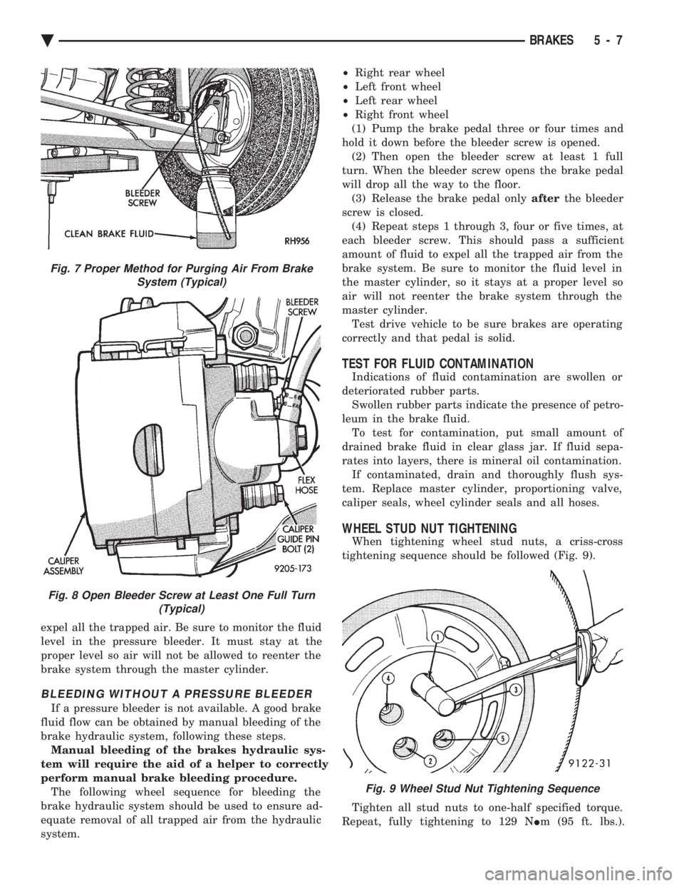
To bleed the brake system. Attach a clear plastic
hose to the bleeder screw starting at the right rear
wheel and feed the hose into a clear jar containing
fresh brake fluid (Fig. 7). Next, open the bleeder screw at least one full turn
or more to obtain an adequate flow of brake fluid
(Fig. 8).
CAUTION: Just cracking the bleeder screw often re-
stricts fluid flow, and a slow, weak fluid discharge
will NOT get all the air out.
After 4 to 8 ounces of fluid has been bled through
the brake system at this wheel. And an air-free flow
is maintained in the clear plastic hose and jar, this
will indicate a good bleed. Repeat the procedure at all the other remaining
bleeder screws. Then check the pedal for travel. If
pedal travel is excessive or has not been improved.
Enough fluid has not passed through the system to
Fig. 5 Brake Drum Adjustment With Tool C-3784
Fig. 6 Trapped Air in Brake Line
5 - 6 BRAKES Ä
Page 157 of 2438
expel all the trapped air. Be sure to monitor the fluid
level in the pressure bleeder. It must stay at the
proper level so air will not be allowed to reenter the
brake system through the master cylinder.
BLEEDING WITHOUT A PRESSURE BLEEDER
If a pressure bleeder is not available. A good brake
fluid flow can be obtained by manual bleeding of the
brake hydraulic system, following these steps. Manual bleeding of the brakes hydraulic sys-
tem will require the aid of a helper to correctly
perform manual brake bleeding procedure. The following wheel sequence for bleeding the
brake hydraulic system should be used to ensure ad-
equate removal of all trapped air from the hydraulic
system. ²
Right rear wheel
² Left front wheel
² Left rear wheel
² Right front wheel
(1) Pump the brake pedal three or four times and
hold it down before the bleeder screw is opened. (2) Then open the bleeder screw at least 1 full
turn. When the bleeder screw opens the brake pedal
will drop all the way to the floor. (3) Release the brake pedal only afterthe bleeder
screw is closed. (4) Repeat steps 1 through 3, four or five times, at
each bleeder screw. This should pass a sufficient
amount of fluid to expel all the trapped air from the
brake system. Be sure to monitor the fluid level in
the master cylinder, so it stays at a proper level so
air will not reenter the brake system through the
master cylinder. Test drive vehicle to be sure brakes are operating
correctly and that pedal is solid.
TEST FOR FLUID CONTAMINATION
Indications of fluid contamination are swollen or
deteriorated rubber parts. Swollen rubber parts indicate the presence of petro-
leum in the brake fluid. To test for contamination, put small amount of
drained brake fluid in clear glass jar. If fluid sepa-
rates into layers, there is mineral oil contamination. If contaminated, drain and thoroughly flush sys-
tem. Replace master cylinder, proportioning valve,
caliper seals, wheel cylinder seals and all hoses.
WHEEL STUD NUT TIGHTENING
When tightening wheel stud nuts, a criss-cross
tightening sequence should be followed (Fig. 9).
Tighten all stud nuts to one-half specified torque.
Repeat, fully tightening to 129 N Im (95 ft. lbs.).
Fig. 9 Wheel Stud Nut Tightening Sequence
Fig. 7 Proper Method for Purging Air From Brake
System (Typical)
Fig. 8 Open Bleeder Screw at Least One Full Turn (Typical)
Ä BRAKES 5 - 7
Page 173 of 2438
WHEEL CYLINDERS INDEX
page page
General Information ....................... 23
Installing Wheel Cylinders .................. 24 Service Procedures
....................... 23
GENERAL INFORMATION
The piston boots are of the push-on type and pre-
vent moisture from entering the wheel cylinder. To perform service operations or inspections of the
rear wheel brake cylinders. It will be necessary to re-
move the cylinders from the support plate and disas-
semble on the bench.
CAUTION: Wheel cylinders with cup expanders
must have cup expanders after any service proce-
dures (reconditioning or replacement).
SERVICE PROCEDURES
REMOVING WHEEL CYLINDERS FROM BRAKE SUPPORT PLATES
With brake drums removed, inspect the wheel cyl-
inder boots for evidence of a brake fluid leak. Then
block the brake pedal in the stroke position, and vi-
sually check the boots for cuts, tears, or heat cracks.
If any of these conditions exist, the wheel cylinders
should be completely cleaned, inspected and new
parts installed. (A slight amount of fluid on the boot
may not be a leak, but may be preservative fluid
used at assembly.) (1) In case of a leak, remove brake shoes, (replace
if soaked with grease or brake fluid.) (2) Thoroughly clean area of wheel cylinder, where
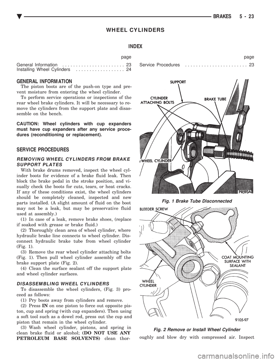
hydraulic brake line connects to wheel cylinder. Dis-
connect hydraulic brake tube from wheel cylinder
(Fig. 1). (3) Remove the rear wheel cylinder attaching bolts
(Fig. 1). Then pull wheel cylinder assembly off the
brake support plate (Fig. 2). (4) Clean the surface sealant off the support plate
and wheel cylinder surfaces.
DISASSEMBLING WHEEL CYLINDERS
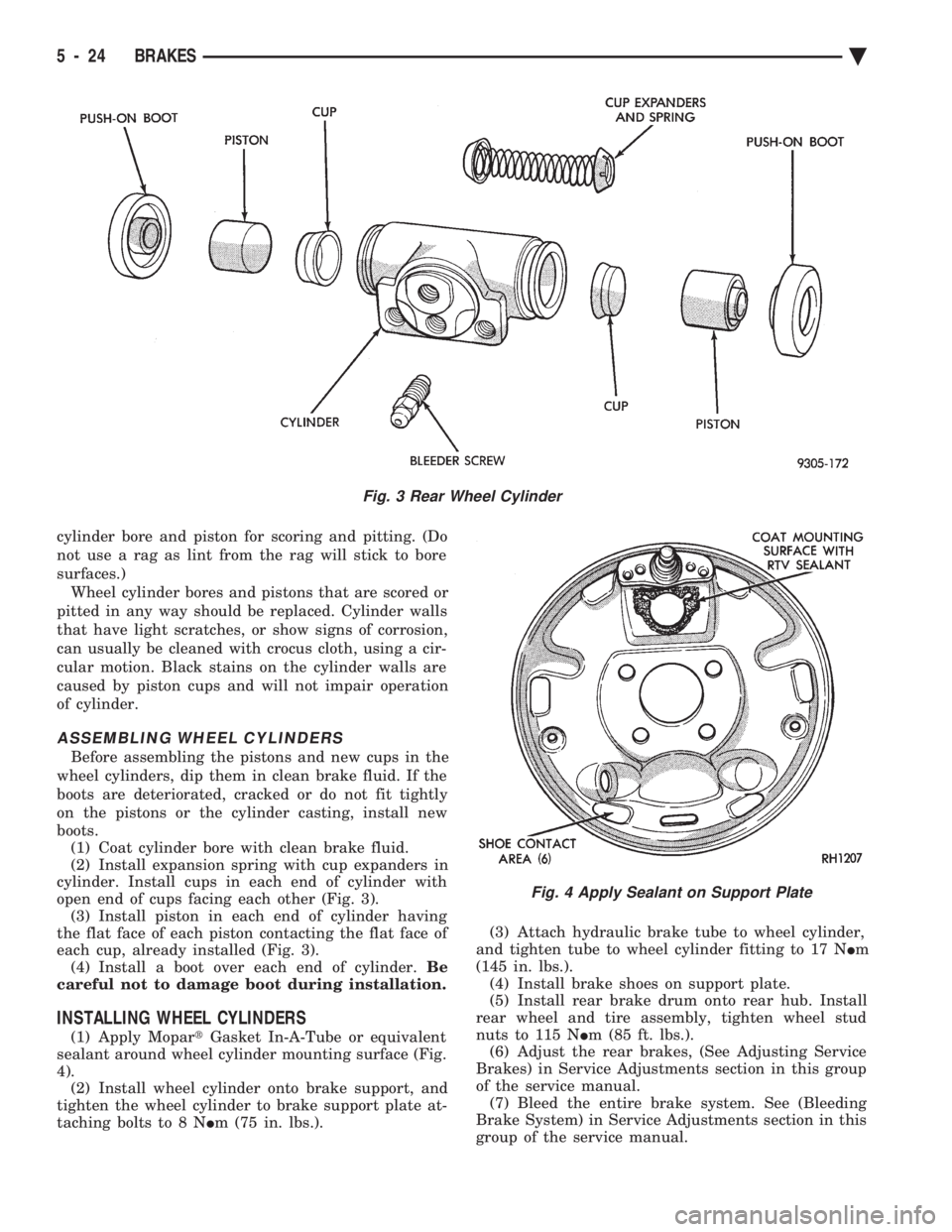
To disassemble the wheel cylinders, (Fig. 3) pro-
ceed as follows: (1) Pry boots away from cylinders and remove.
(2) Press INon one piston to force out opposite pis-
ton, cup and spring (with cup expanders). Then using
a soft tool such as a dowel rod, press out the cup and
piston that remain in the wheel cylinder. (3) Wash wheel cylinder, pistons, and spring in
clean brake fluid or alcohol; (DO NOT USE ANY
PETROLEUM BASE SOLVENTS) clean thor- oughly and blow dry with compressed air. Inspect
Fig. 1 Brake Tube Disconnected
Fig. 2 Remove or Install Wheel Cylinder
Ä
BRAKES 5 - 23
Page 174 of 2438
cylinder bore and piston for scoring and pitting. (Do
not use a rag as lint from the rag will stick to bore
surfaces.) Wheel cylinder bores and pistons that are scored or
pitted in any way should be replaced. Cylinder walls
that have light scratches, or show signs of corrosion,
can usually be cleaned with crocus cloth, using a cir-
cular motion. Black stains on the cylinder walls are
caused by piston cups and will not impair operation
of cylinder.
ASSEMBLING WHEEL CYLINDERS
Before assembling the pistons and new cups in the
wheel cylinders, dip them in clean brake fluid. If the
boots are deteriorated, cracked or do not fit tightly
on the pistons or the cylinder casting, install new
boots. (1) Coat cylinder bore with clean brake fluid.
(2) Install expansion spring with cup expanders in
cylinder. Install cups in each end of cylinder with
open end of cups facing each other (Fig. 3). (3) Install piston in each end of cylinder having
the flat face of each piston contacting the flat face of
each cup, already installed (Fig. 3). (4) Install a boot over each end of cylinder. Be
careful not to damage boot during installation.
INSTALLING WHEEL CYLINDERS
(1) Apply Mopar tGasket In-A-Tube or equivalent
sealant around wheel cylinder mounting surface (Fig.
4). (2) Install wheel cylinder onto brake support, and
tighten the wheel cylinder to brake support plate at-
taching bolts to 8 N Im (75 in. lbs.). (3) Attach hydraulic brake tube to wheel cylinder,
and tighten tube to wheel cylinder fitting to 17 N Im
(145 in. lbs.). (4) Install brake shoes on support plate.
(5) Install rear brake drum onto rear hub. Install
rear wheel and tire assembly, tighten wheel stud
nuts to 115 N Im (85 ft. lbs.).
(6) Adjust the rear brakes, (See Adjusting Service
Brakes) in Service Adjustments section in this group
of the service manual. (7) Bleed the entire brake system. See (Bleeding
Brake System) in Service Adjustments section in this
group of the service manual.
Fig. 3 Rear Wheel Cylinder
Fig. 4 Apply Sealant on Support Plate
5 - 24 BRAKES Ä
Page 177 of 2438
to the rear will be lower than the front brakes. This will
prevent premature rear wheel lock-up and skid. If
hydraulic pressure is lost in one half of the diagonally
split system, the operation of the proportioning valve
in the remaining half is not effected.
ABS BRAKE PROPORTIONING VALVE OPERATION
On vehicles using the ABS braking system, screw in
proportioning valves are used in place of the conven-
tional differential pressure/proportioning valve. Each rear brake circuit has its own screw-in propor-
tioning valve which is attached to the rear brake outlet
ports of the hydraulic assembly. These valves limit
brake pressure to the rear brakes after a certain
pressure is reached. This improves front to rear brake
balance during normal braking.
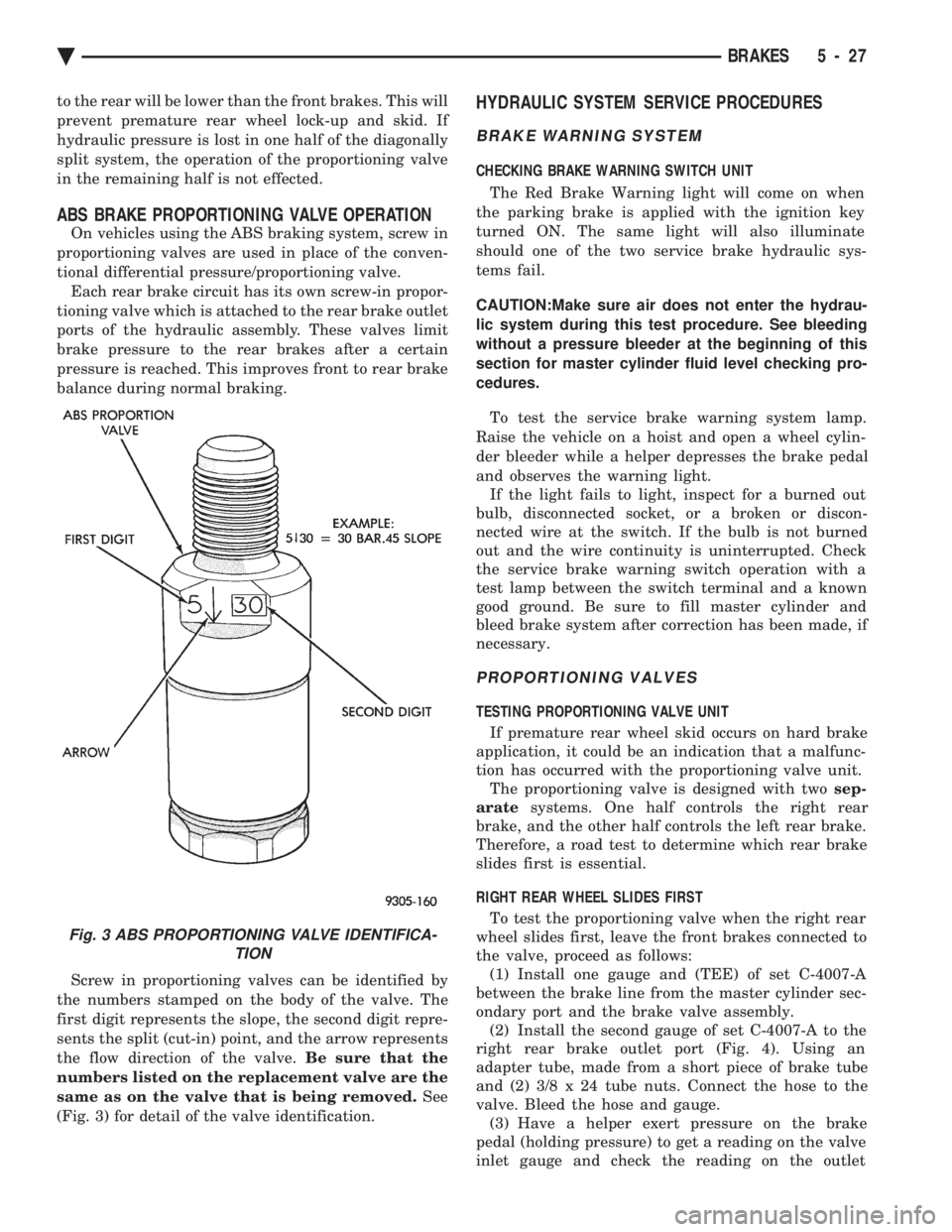
Screw in proportioning valves can be identified by
the numbers stamped on the body of the valve. The
first digit represents the slope, the second digit repre-
sents the split (cut-in) point, and the arrow represents
the flow direction of the valve. Be sure that the
numbers listed on the replacement valve are the
same as on the valve that is being removed. See
(Fig. 3) for detail of the valve identification.
HYDRAULIC SYSTEM SERVICE PROCEDURES
BRAKE WARNING SYSTEM
CHECKING BRAKE WARNING SWITCH UNIT
The Red Brake Warning light will come on when
the parking brake is applied with the ignition key
turned ON. The same light will also illuminate
should one of the two service brake hydraulic sys-
tems fail.
CAUTION:Make sure air does not enter the hydrau-
lic system during this test procedure. See bleeding
without a pressure bleeder at the beginning of this
section for master cylinder fluid level checking pro-
cedures.
To test the service brake warning system lamp.
Raise the vehicle on a hoist and open a wheel cylin-
der bleeder while a helper depresses the brake pedal
and observes the warning light. If the light fails to light, inspect for a burned out
bulb, disconnected socket, or a broken or discon-
nected wire at the switch. If the bulb is not burned
out and the wire continuity is uninterrupted. Check
the service brake warning switch operation with a
test lamp between the switch terminal and a known
good ground. Be sure to fill master cylinder and
bleed brake system after correction has been made, if
necessary.
PROPORTIONING VALVES
TESTING PROPORTIONING VALVE UNIT
If premature rear wheel skid occurs on hard brake
application, it could be an indication that a malfunc-
tion has occurred with the proportioning valve unit. The proportioning valve is designed with two sep-
arate systems. One half controls the right rear
brake, and the other half controls the left rear brake.
Therefore, a road test to determine which rear brake
slides first is essential.
RIGHT REAR WHEEL SLIDES FIRST To test the proportioning valve when the right rear
wheel slides first, leave the front brakes connected to
the valve, proceed as follows: (1) Install one gauge and (TEE) of set C-4007-A
between the brake line from the master cylinder sec-
ondary port and the brake valve assembly. (2) Install the second gauge of set C-4007-A to the
right rear brake outlet port (Fig. 4). Using an
adapter tube, made from a short piece of brake tube
and (2) 3/8 x 24 tube nuts. Connect the hose to the
valve. Bleed the hose and gauge. (3) Have a helper exert pressure on the brake
pedal (holding pressure) to get a reading on the valve
inlet gauge and check the reading on the outlet
Fig. 3 ABS PROPORTIONING VALVE IDENTIFICA- TION
Ä BRAKES 5 - 27
Page 182 of 2438
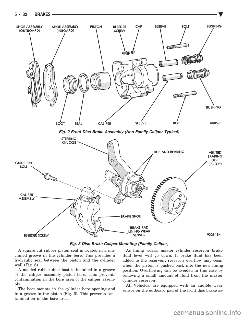
A square cut rubber piston seal is located in a ma-
chined groove in the cylinder bore. This provides a
hydraulic seal between the piston and the cylinder
wall (Fig. 6). A molded rubber dust boot is installed in a groove
of the caliper assembly piston bore. This prevents
contamination in the bore area of the caliper assem-
bly. The boot mounts in the cylinder bore opening and
in a groove in the piston (Fig. 6). This prevents con-
tamination in the bore area. As lining wears, master cylinder reservoir brake
fluid level will go down. If brake fluid has been
added to the reservoir, reservoir overflow may occur
when the piston is pushed back into the new lining
position. Overflowing can be avoided in this case by
removing a small amount of fluid from the master
cylinder reservoir. All Vehicles, are equipped with an audible wear
sensor on the outboard pad of the front disc brake as-
Fig. 2 Front Disc Brake Assembly (Non-Family Caliper Typical)
Fig. 3 Disc Brake Caliper Mounting (Family Caliper)
5 - 32 BRAKES Ä
Page 189 of 2438
CLEANING AND INSPECTION
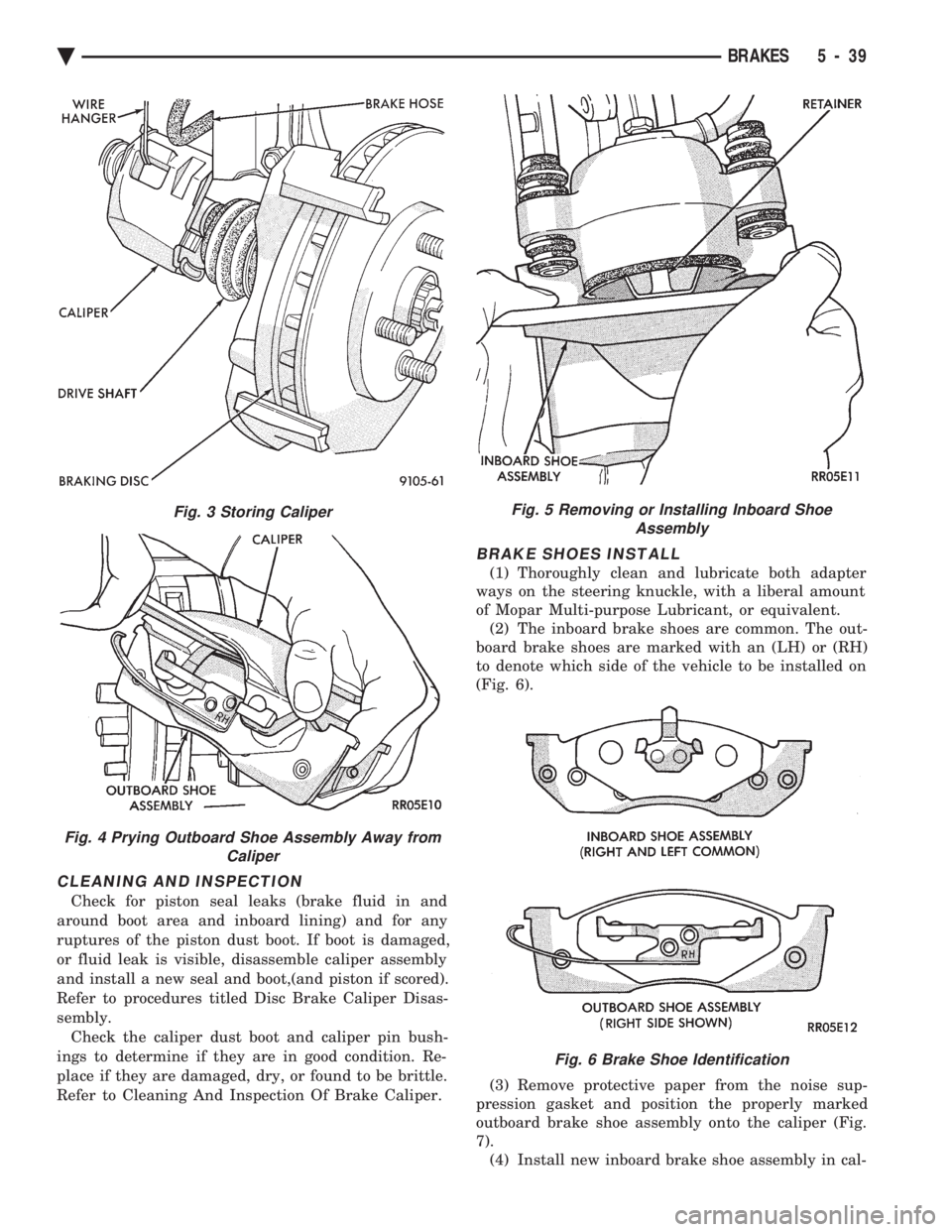
Check for piston seal leaks (brake fluid in and
around boot area and inboard lining) and for any
ruptures of the piston dust boot. If boot is damaged,
or fluid leak is visible, disassemble caliper assembly
and install a new seal and boot,(and piston if scored).
Refer to procedures titled Disc Brake Caliper Disas-
sembly. Check the caliper dust boot and caliper pin bush-
ings to determine if they are in good condition. Re-
place if they are damaged, dry, or found to be brittle.
Refer to Cleaning And Inspection Of Brake Caliper.
BRAKE SHOES INSTALL
(1) Thoroughly clean and lubricate both adapter
ways on the steering knuckle, with a liberal amount
of Mopar Multi-purpose Lubricant, or equivalent. (2) The inboard brake shoes are common. The out-
board brake shoes are marked with an (LH) or (RH)
to denote which side of the vehicle to be installed on
(Fig. 6).
(3) Remove protective paper from the noise sup-
pression gasket and position the properly marked
outboard brake shoe assembly onto the caliper (Fig.
7). (4) Install new inboard brake shoe assembly in cal-
Fig. 3 Storing Caliper
Fig. 4 Prying Outboard Shoe Assembly Away from Caliper
Fig. 5 Removing or Installing Inboard ShoeAssembly
Fig. 6 Brake Shoe Identification
Ä BRAKES 5 - 39
Page 190 of 2438
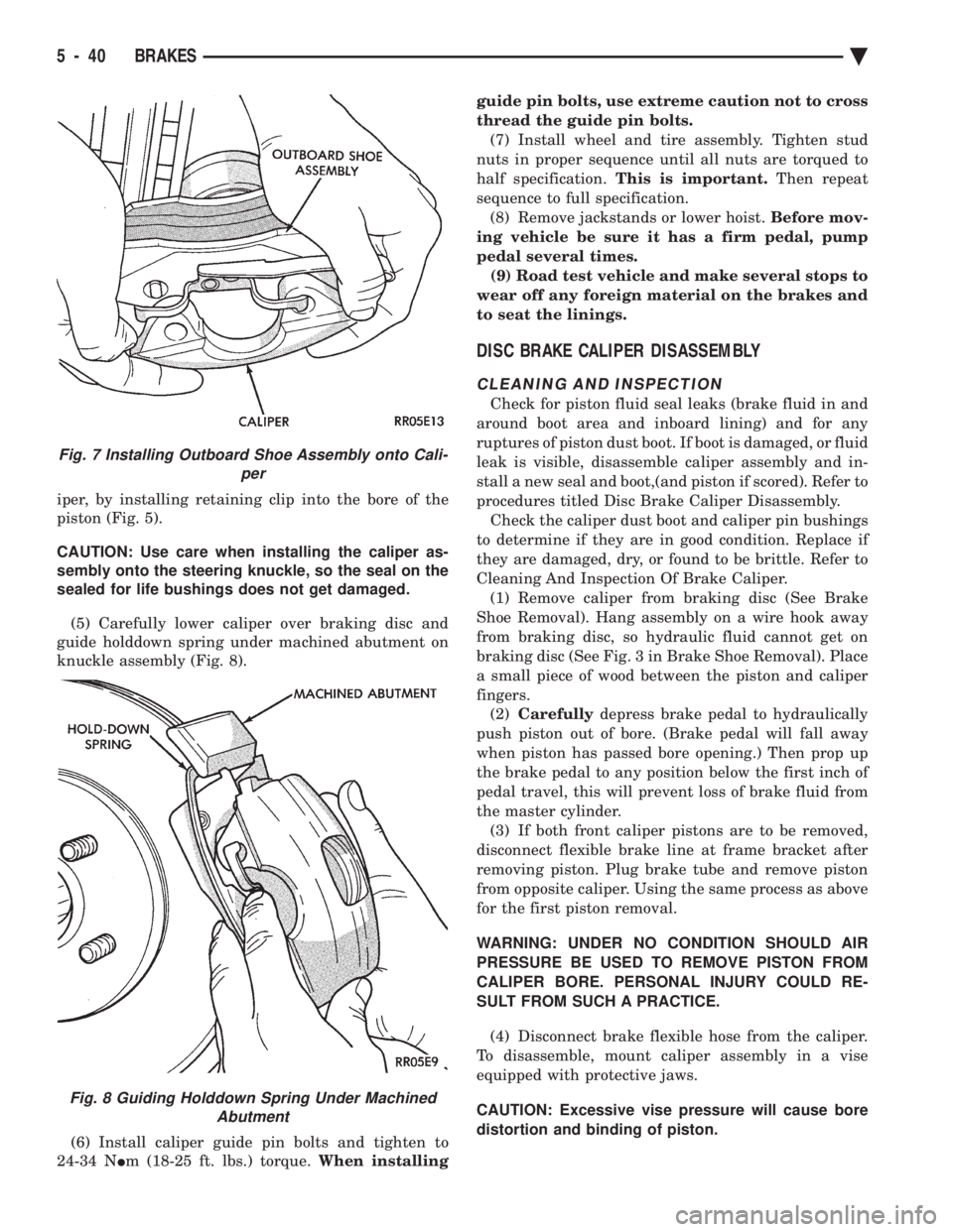
iper, by installing retaining clip into the bore of the
piston (Fig. 5).
CAUTION: Use care when installing the caliper as-
sembly onto the steering knuckle, so the seal on the
sealed for life bushings does not get damaged.
(5) Carefully lower caliper over braking disc and
guide holddown spring under machined abutment on
knuckle assembly (Fig. 8).
(6) Install caliper guide pin bolts and tighten to
24-34 N Im (18-25 ft. lbs.) torque. When installing guide pin bolts, use extreme caution not to cross
thread the guide pin bolts.
(7) Install wheel and tire assembly. Tighten stud
nuts in proper sequence until all nuts are torqued to
half specification. This is important. Then repeat
sequence to full specification. (8) Remove jackstands or lower hoist. Before mov-
ing vehicle be sure it has a firm pedal, pump
pedal several times. (9) Road test vehicle and make several stops to
wear off any foreign material on the brakes and
to seat the linings.
DISC BRAKE CALIPER DISASSEMBLY
CLEANING AND INSPECTION
Check for piston fluid seal leaks (brake fluid in and
around boot area and inboard lining) and for any
ruptures of piston dust boot. If boot is damaged, or fluid
leak is visible, disassemble caliper assembly and in-
stall a new seal and boot,(and piston if scored). Refer to
procedures titled Disc Brake Caliper Disassembly. Check the caliper dust boot and caliper pin bushings
to determine if they are in good condition. Replace if
they are damaged, dry, or found to be brittle. Refer to
Cleaning And Inspection Of Brake Caliper. (1) Remove caliper from braking disc (See Brake
Shoe Removal). Hang assembly on a wire hook away
from braking disc, so hydraulic fluid cannot get on
braking disc (See Fig. 3 in Brake Shoe Removal). Place
a small piece of wood between the piston and caliper
fingers. (2) Carefully depress brake pedal to hydraulically
push piston out of bore. (Brake pedal will fall away
when piston has passed bore opening.) Then prop up
the brake pedal to any position below the first inch of
pedal travel, this will prevent loss of brake fluid from
the master cylinder. (3) If both front caliper pistons are to be removed,
disconnect flexible brake line at frame bracket after
removing piston. Plug brake tube and remove piston
from opposite caliper. Using the same process as above
for the first piston removal.
WARNING: UNDER NO CONDITION SHOULD AIR
PRESSURE BE USED TO REMOVE PISTON FROM
CALIPER BORE. PERSONAL INJURY COULD RE-
SULT FROM SUCH A PRACTICE.
(4) Disconnect brake flexible hose from the caliper.
To disassemble, mount caliper assembly in a vise
equipped with protective jaws.
CAUTION: Excessive vise pressure will cause bore
distortion and binding of piston.
Fig. 7 Installing Outboard Shoe Assembly onto Cali- per
Fig. 8 Guiding Holddown Spring Under MachinedAbutment
5 - 40 BRAKES Ä
Page 191 of 2438
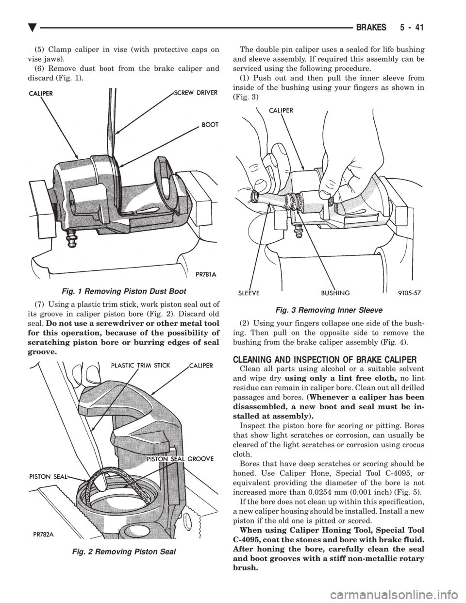
(5) Clamp caliper in vise (with protective caps on
vise jaws). (6) Remove dust boot from the brake caliper and
discard (Fig. 1).
(7) Using a plastic trim stick, work piston seal out of
its groove in caliper piston bore (Fig. 2). Discard old
seal. Do not use a screwdriver or other metal tool
for this operation, because of the possibility of
scratching piston bore or burring edges of seal
groove. The double pin caliper uses a sealed for life bushing
and sleeve assembly. If required this assembly can be
serviced using the following procedure. (1) Push out and then pull the inner sleeve from
inside of the bushing using your fingers as shown in
(Fig. 3)
(2) Using your fingers collapse one side of the bush-
ing. Then pull on the opposite side to remove the
bushing from the brake caliper assembly (Fig. 4).
CLEANING AND INSPECTION OF BRAKE CALIPER
Clean all parts using alcohol or a suitable solvent
and wipe dry using only a lint free cloth, no lint
residue can remain in caliper bore. Clean out all drilled
passages and bores. (Whenever a caliper has been
disassembled, a new boot and seal must be in-
stalled at assembly). Inspect the piston bore for scoring or pitting. Bores
that show light scratches or corrosion, can usually be
cleared of the light scratches or corrosion using crocus
cloth. Bores that have deep scratches or scoring should be
honed. Use Caliper Hone, Special Tool C-4095, or
equivalent providing the diameter of the bore is not
increased more than 0.0254 mm (0.001 inch) (Fig. 5). If the bore does not clean up within this specification,
a new caliper housing should be installed. Install a new
piston if the old one is pitted or scored. When using Caliper Honing Tool, Special Tool
C-4095, coat the stones and bore with brake fluid.
After honing the bore, carefully clean the seal
and boot grooves with a stiff non-metallic rotary
brush.
Fig. 1 Removing Piston Dust Boot
Fig. 2 Removing Piston Seal
Fig. 3 Removing Inner Sleeve
Ä BRAKES 5 - 41
Page 192 of 2438
Use extreme care in cleaning the caliper after
honing. Remove all dirt and grit by flushing the
caliper with brake fluid; wipe dry with a clean,
lint free cloth and then clean a second time.
ASSEMBLING DISC BRAKE CALIPER
Clamp caliper in vise (with protective caps on vise
jaws).
CAUTION: Excessive vise pressure will cause bore
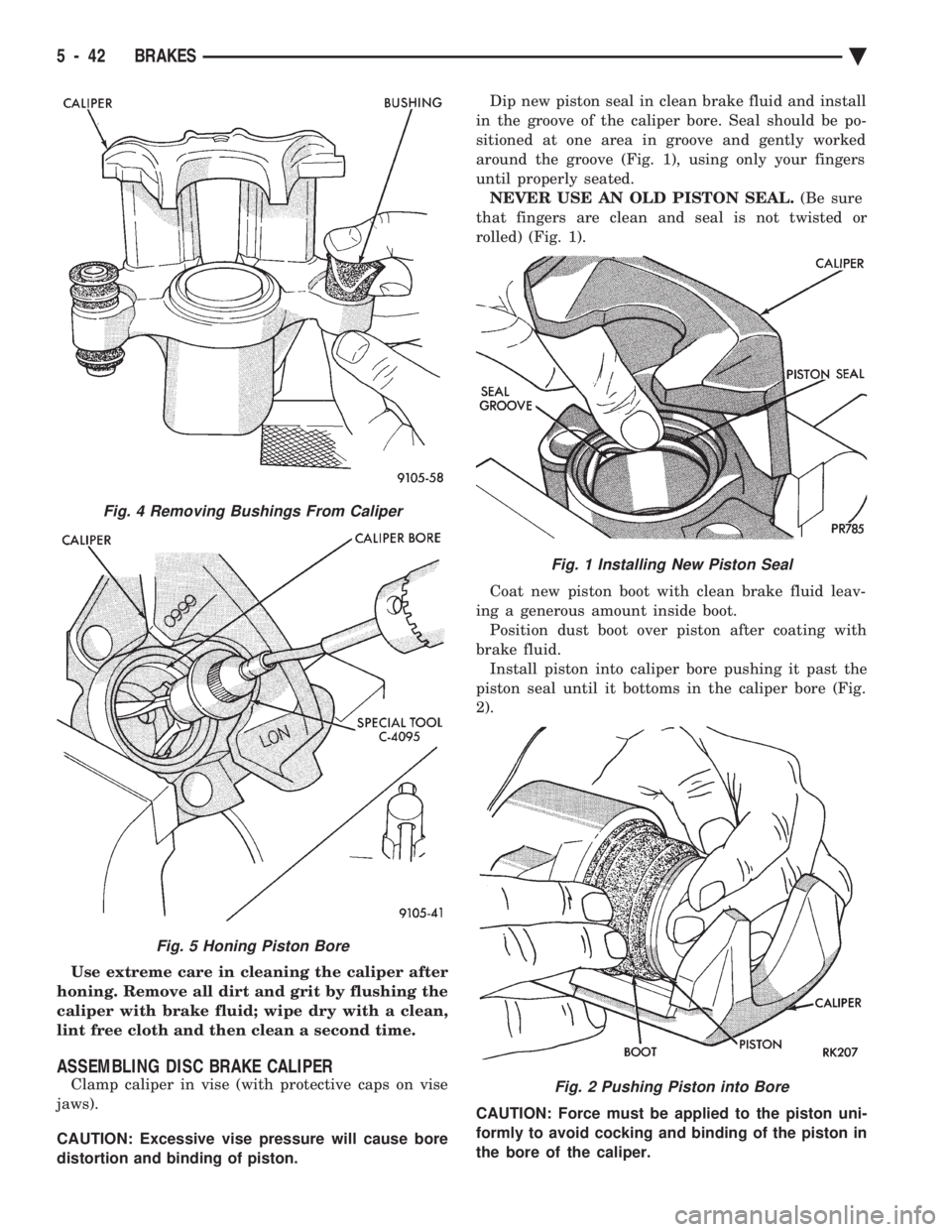
distortion and binding of piston. Dip new piston seal in clean brake fluid and install
in the groove of the caliper bore. Seal should be po-
sitioned at one area in groove and gently worked
around the groove (Fig. 1), using only your fingers
until properly seated. NEVER USE AN OLD PISTON SEAL. (Be sure
that fingers are clean and seal is not twisted or
rolled) (Fig. 1).
Coat new piston boot with clean brake fluid leav-
ing a generous amount inside boot. Position dust boot over piston after coating with
brake fluid. Install piston into caliper bore pushing it past the
piston seal until it bottoms in the caliper bore (Fig.
2).
CAUTION: Force must be applied to the piston uni-
formly to avoid cocking and binding of the piston in
the bore of the caliper.
Fig. 1 Installing New Piston Seal
Fig. 2 Pushing Piston into Bore
Fig. 4 Removing Bushings From Caliper
Fig. 5 Honing Piston Bore
5 - 42 BRAKES Ä