turn signal bulb CHEVROLET PLYMOUTH ACCLAIM 1993 Service Manual
[x] Cancel search | Manufacturer: CHEVROLET, Model Year: 1993, Model line: PLYMOUTH ACCLAIM, Model: CHEVROLET PLYMOUTH ACCLAIM 1993Pages: 2438, PDF Size: 74.98 MB
Page 33 of 2438
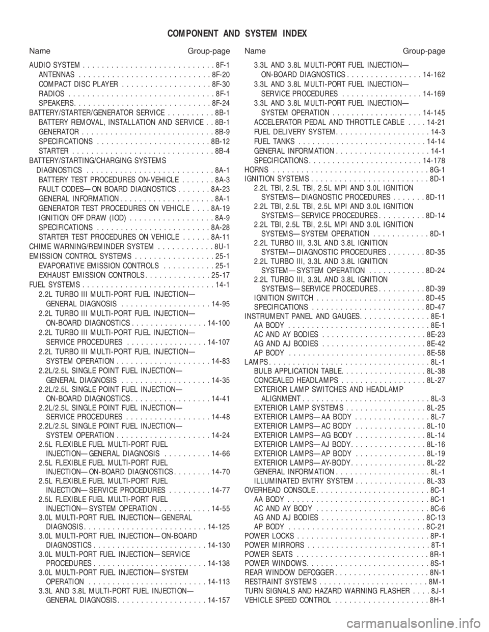
COMPONENT AND SYSTEM INDEX
Name Group-page Name Group-page
AUDIO SYSTEM ............................ 8F-1
ANTENNAS ............................ 8F-20
COMPACT DISC PLAYER ................... 8F-30
RADIOS ............................... 8F-1
SPEAKERS ............................. 8F-24
BATTERY/STARTER/GENERATOR SERVICE ..........8B-1
BATTERY REMOVAL, INSTALLATION AND SERVICE . . 8B-1
GENERATOR ............................ 8B-9
SPECIFICATIONS ........................ 8B-12
STARTER .............................. 8B-4
BATTERY/STARTING/CHARGING SYSTEMS DIAGNOSTICS ........................... 8A-1
BATTERY TEST PROCEDURES ON-VEHICLE .......8A-3
FAULT CODESÐON BOARD DIAGNOSTICS .......8A-23
GENERAL INFORMATION .................... 8A-1
GENERATOR TEST PROCEDURES ON VEHICLE ....8A-19
IGNITION OFF DRAW (IOD) ..................8A-9
SPECIFICATIONS ........................ 8A-28
STARTER TEST PROCEDURES ON VEHICLE ......8A-11
CHIME WARNING/REMINDER SYSTEM ............8U-1
EMISSION CONTROL SYSTEMS .................25-1
EVAPORATIVE EMISSION CONTROLS ...........25-1
EXHAUST EMISSION CONTROLS ..............25-17
FUEL SYSTEMS ............................ 14-1
2.2L TURBO III MULTI-PORT FUEL INJECTIONÐ GENERAL DIAGNOSIS ................... 14-95
2.2L TURBO III MULTI-PORT FUEL INJECTIONÐ ON-BOARD DIAGNOSTICS ................14-100
2.2L TURBO III MULTI-PORT FUEL INJECTIONÐ SERVICE PROCEDURES .................14-107
2.2L TURBO III MULTI-PORT FUEL INJECTIONÐ SYSTEM OPERATION .................... 14-83
2.2L/2.5L SINGLE POINT FUEL INJECTIONÐ GENERAL DIAGNOSIS ................... 14-35
2.2L/2.5L SINGLE POINT FUEL INJECTIONÐ ON-BOARD DIAGNOSTICS .................14-41
2.2L/2.5L SINGLE POINT FUEL INJECTIONÐ SERVICE PROCEDURES .................. 14-48
2.2L/2.5L SINGLE POINT FUEL INJECTIONÐ SYSTEM OPERATION .................... 14-24
2.5L FLEXIBLE FUEL MULTI-PORT FUEL INJECTIONÐGENERAL DIAGNOSIS ..........14-66
2.5L FLEXIBLE FUEL MULTI-PORT FUEL INJECTIONÐON-BOARD DIAGNOSTICS ........14-70
2.5L FLEXIBLE FUEL MULTI-PORT FUEL INJECTIONÐSERVICE PROCEDURES .........14-77
2.5L FLEXIBLE FUEL MULTI-PORT FUEL INJECTIONÐSYSTEM OPERATION ...........14-55
3.0L MULTI-PORT FUEL INJECTIONÐGENERAL DIAGNOSIS .......................... 14-125
3.0L MULTI-PORT FUEL INJECTIONÐON-BOARD DIAGNOSTICS ........................ 14-130
3.0L MULTI-PORT FUEL INJECTIONÐSERVICE PROCEDURES ........................ 14-138
3.0L MULTI-PORT FUEL INJECTIONÐSYSTEM OPERATION ......................... 14-113
3.3L AND 3.8L MULTI-PORT FUEL INJECTIONÐ GENERAL DIAGNOSIS ................... 14-157 3.3L AND 3.8L MULTI-PORT FUEL INJECTIONÐ
ON-BOARD DIAGNOSTICS ................14-162
3.3L AND 3.8L MULTI-PORT FUEL INJECTIONÐ SERVICE PROCEDURES .................14-169
3.3L AND 3.8L MULTI-PORT FUEL INJECTIONÐ SYSTEM OPERATION ................... 14-145
ACCELERATOR PEDAL AND THROTTLE CABLE ....14-21
FUEL DELIVERY SYSTEM .................... 14-3
FUEL TANKS ........................... 14-14
GENERAL INFORMATION .................... 14-1
SPECIFICATIONS ........................ 14-178
HORNS ................................. 8G-1
IGNITION SYSTEMS ......................... 8D-1
2.2L TBI, 2.5L TBI, 2.5L MPI AND 3.0L IGNITION SYSTEMSÐDIAGNOSTIC PROCEDURES .......8D-11
2.2L TBI, 2.5L TBI, 2.5L MPI AND 3.0L IGNITION SYSTEMSÐSERVICE PROCEDURES ..........8D-14
2.2L TBI, 2.5L TBI, 2.5L MPI AND 3.0L IGNITION SYSTEMSÐSYSTEM OPERATION ............8D-1
2.2L TURBO III, 3.3L AND 3.8L IGNITION SYSTEMÐDIAGNOSTIC PROCEDURES ........8D-35
2.2L TURBO III, 3.3L AND 3.8L IGNITION SYSTEMÐSYSTEM OPERATION ............8D-24
2.2L TURBO III, 3.3L AND 3.8L IGNITION SYSTEMSÐSERVICE PROCEDURES ..........8D-39
IGNITION SWITCH ....................... 8D-45
SPECIFICATIONS ........................ 8D-47
INSTRUMENT PANEL AND GAUGES ...............8E-1
AA BODY .............................. 8E-1
AC AND AY BODIES ...................... 8E-23
AG AND AJ BODIES ...................... 8E-42
AP BODY ............................. 8E-58
LAMPS .................................. 8L-1
BULB APPLICATION TABLE ..................8L-38
CONCEALED HEADLAMPS ..................8L-27
EXTERIOR LAMP SWITCHES AND HEADLAMP ALIGNMENT ........................... 8L-3
EXTERIOR LAMP SYSTEMS .................8L-25
EXTERIOR LAMPSÐAA BODY ................8L-7
EXTERIOR LAMPSÐAC BODY ...............8L-10
EXTERIOR LAMPSÐAG BODY ...............8L-14
EXTERIOR LAMPSÐAJ BODY ................8L-16
EXTERIOR LAMPSÐAP BODY ...............8L-19
EXTERIOR LAMPSÐAY-BODY ................8L-22
GENERAL INFORMATION .................... 8L-1
ILLUMINATED ENTRY SYSTEM ...............8L-33
OVERHEAD CONSOLE ........................ 8C-1
AA BODY .............................. 8C-1
AC AND AY BODY ........................ 8C-6
AG AND AJ BODIES ...................... 8C-13
AP BODY ............................. 8C-21
POWER LOCKS ............................ 8P-1
POWER MIRRORS ..........................8T-1
POWER SEATS ............................ 8R-1
POWER WINDOWS .......................... 8S-1
REAR WINDOW DEFOGGER .................... 8N-1
RESTRAINT SYSTEMS ....................... 8M-1
TURN SIGNALS AND HAZARD WARNING FLASHER ....8J-1
VEHICLE SPEED CONTROL .................... 8H-1
Page 225 of 2438
ABS EQUIPPED VEHICLE PERFORMANCE
Anti-Lock Brakes provide the driver with some
steering control during hard braking. However there
are conditions where the system does not provide any
benefit. In particular, hydroplaning is still possible
when the tires ride on a film of water. Hydroplaning
results in the vehicle tires leaving the road surface
rendering the vehicle almost uncontrollable. In addi-
tion, extreme steering maneuvers at high speed or
high speed cornering beyond limits of tire adhesion
to the road surface may cause vehicle skidding. So,
the ABS system is termed Anti-Lock instead of Anti-
Skid. One of the significant benefits of the ABS system is
that of maintaining steering control during hard
braking or during braking on slippery surfaces. It is
therefore possible to steer the vehicle while braking
on almost any road surface.
ABS SYSTEM SELF-DIAGNOSTICS
The ABS system has been designed with Self Diag-
nostic Capability. There are two self checks the sys-
tems performs every time the vehicle is started.
First, when the key is turned on the system performs
an electrical check called Start-Up Cycle. During this
check, the Red Brake Warning Lamp and the Amber
Anti-Lock Warning Lamp are illuminated. Then
turned off at the end of the test, after about 1 to 2
seconds. When the vehicle reaches a speed of about 3
to 4 miles per hour. The system performs a func-
tional check called Drive-Off. During Drive-Off. hy-
draulic valves are activated briefly to test their
function. Drive-Off can be detected as a series of
rapid clicks upon driving off the first time the car is
started. If the brake pedal is applied during Drive-
Off, the test is by-passed. Both of these conditions
are a normal part of the system self test. Most fault
conditions will set a ABS Fault Code in the (CAB),
which can be retrieved to aid in fault diagnosis. De-
tails can be found in Diagnosis Section.
ABS WARNING SYSTEMS OPERATION
The ABS system uses two methods for notifying
the driver of a system malfunction. These include the
standard Red Brake Warning Lamp and an Amber
Anti-Lock Warning Lamp, both located in the instru-
ment cluster. The purpose of these two lamps are dis-
cussed in detail below.
RED BRAKE WARNING LAMP
The Red Brake Warning Lamp, located in the in-
strument cluster, will Turn On to warn the driver of
brake system conditions that may result in reduced
braking ability. The lamp is also turned on when the
parking brake is not fully released. Conditions which
may cause the Red Brake Warning Lamp to Turn On
include: ²
Parking brake not fully released. If the parking
brake is applied or not fully released. The switch on the
parking brake pedal assembly will ground the Red
Brake Warning Lamp circuit and cause the lamp to
turn on. On vehicles equipped with mechanical instru-
ment clusters, the Amber Anti-Lock Lamp will turn on
if the vehicle is driven above 3 miles per hour with the
Parking Brake applied.
² Low brake fluid. The fluid level sensor in the hy-
draulic assembly reservoir will ground the Red Brake
Warning Lamp circuit if low brake fluid level is de-
tected. In addition, ABS will be deactivated above 3
miles per hour and the Amber Anti-Lock Warning
Lamp will be illuminated. If the vehicle is equipped
with EVIC, a low fluid condition will also cause the
Low Brake Fluid message to appear.
² Low Accumulator Pressure. In the event of low
accumulator pressure, the dual function pressure
switch in the hydraulic assembly will signal the (CAB)
to ground the Red Brake Warning Lamp circuit. This
will cause the Red Brake Warning Lamp to turn on.
Low accumulator pressure also results in the activa-
tion of the Yellow Anti-Lock Warning Lamp. Low accu-
mulator pressure may result in loss of power assist.
² Modulator Or (CAB) Faults. The modulator assem-
bly or (CAB) may turn on the Yellow Anti-Lock Warn-
ing Lamp, if certain faults are detected in either the
modulator assembly or the (CAB).
² Bulb check. As a bulb check, the Red Brake Warning
Lamp will illuminate whenever the ignition switch is
placed in the crank position. Illumination of the red Brake Warning Lamp
may indicate reduced braking ability. A vehicle
that has the Red Brake Warning Lamp ON should
not be driven except to do diagnostic procedures
described in Section 2 of this manual. Most con-
ditions that turn on the Red Brake Warning
Lamp will also turn on the Amber Anti-Lock
Warning Lamp, consequently disabling the Anti-
Lock function.
ANTI-LOCK WARNING LAMP
The Anti-Lock Warning Lamp is located in the in-
strument cluster and is Amber in color. The Amber
Anti-Lock Warning Lamp is illuminated when the
(CAB) detects a condition that results in a shutdown of
Anti-Lock function. The Amber Anti-Lock Warning
Lamp is normally on until the (CAB) completes its self
tests and turns the lamp off. For example, if the (CAB)
is disconnected, the lamp is on. Display of the Amber Anti-Lock Warning Lamp
without the Red Brake Warning Lamp indicates
only that Anti-Lock function has been disabled.
Power assisted normal braking is unaffected.
Ä ANTI-LOCK 10 BRAKE SYSTEM 5 - 75
Page 618 of 2438
(5) For installation reverse above procedure.
(6) Check for proper operation of all components
which are controlled by the pod mounted switch.
TURN SIGNAL AND HAZARD WARNING FLASHER
LOCATION
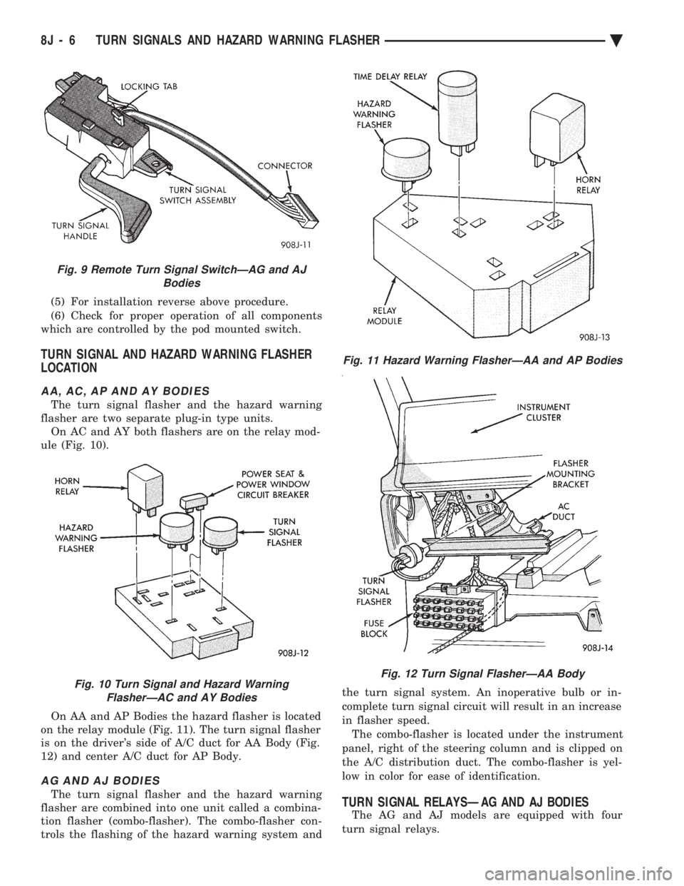
AA, AC, AP AND AY BODIES
The turn signal flasher and the hazard warning
flasher are two separate plug-in type units. On AC and AY both flashers are on the relay mod-
ule (Fig. 10).
On AA and AP Bodies the hazard flasher is located
on the relay module (Fig. 11). The turn signal flasher
is on the driver's side of A/C duct for AA Body (Fig.
12) and center A/C duct for AP Body.
AG AND AJ BODIES
The turn signal flasher and the hazard warning
flasher are combined into one unit called a combina-
tion flasher (combo-flasher). The combo-flasher con-
trols the flashing of the hazard warning system and the turn signal system. An inoperative bulb or in-
complete turn signal circuit will result in an increase
in flasher speed. The combo-flasher is located under the instrument
panel, right of the steering column and is clipped on
the A/C distribution duct. The combo-flasher is yel-
low in color for ease of identification.TURN SIGNAL RELAYSÐAG AND AJ BODIES
The AG and AJ models are equipped with four
turn signal relays.
Fig. 9 Remote Turn Signal SwitchÐAG and AJ Bodies
Fig. 10 Turn Signal and Hazard WarningFlasherÐAC and AY Bodies
Fig. 11 Hazard Warning FlasherÐAA and AP Bodies
Fig. 12 Turn Signal FlasherÐAA Body
8J - 6 TURN SIGNALS AND HAZARD WARNING FLASHER Ä
Page 649 of 2438
EXTERIOR LAMPSÐAA BODY INDEX
page page
Center High-Mounted Stop Lamp (CHMSL) Bulb . . 9
Fog Lamp ............................... 9
Fog Lamp Bulb ........................... 9
Front Side Marker Lamp or Bulb .............. 7
Headlamp Bulb ........................... 7 Headlamp Lens
........................... 7
License Plate Lamp or BulbÐAA/P Body ....... 8
License Plate LampsÐAA/C Body ............. 8
Park and Turn Signal Lamp or Bulb ........... 7
Tail, Stop and Turn Signal and Back-Up Lamp . . . 8
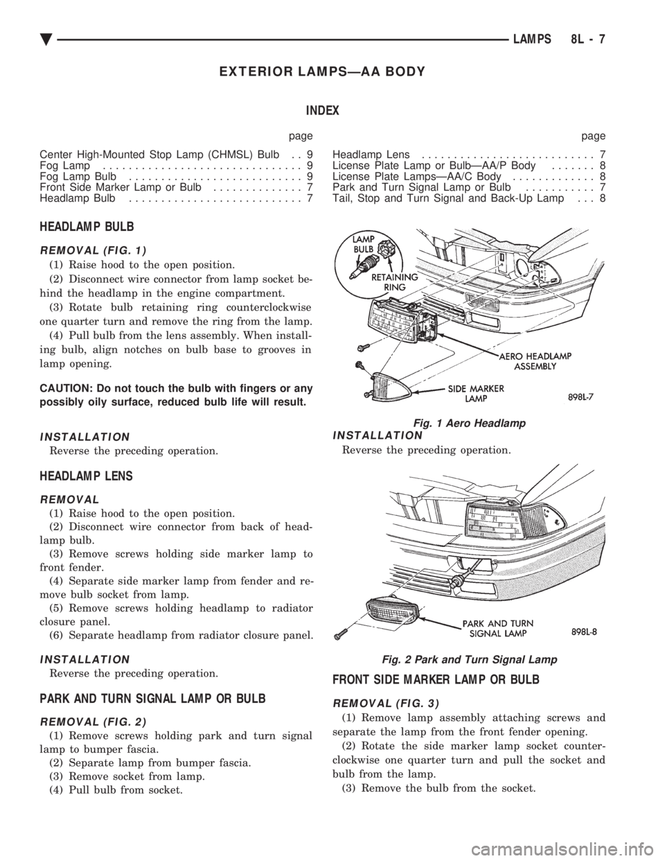
HEADLAMP BULB
REMOVAL (FIG. 1)
(1) Raise hood to the open position.
(2) Disconnect wire connector from lamp socket be-
hind the headlamp in the engine compartment. (3) Rotate bulb retaining ring counterclockwise
one quarter turn and remove the ring from the lamp. (4) Pull bulb from the lens assembly. When install-
ing bulb, align notches on bulb base to grooves in
lamp opening.
CAUTION: Do not touch the bulb with fingers or any
possibly oily surface, reduced bulb life will result.
INSTALLATION
Reverse the preceding operation.
HEADLAMP LENS
REMOVAL
(1) Raise hood to the open position.
(2) Disconnect wire connector from back of head-
lamp bulb. (3) Remove screws holding side marker lamp to
front fender. (4) Separate side marker lamp from fender and re-
move bulb socket from lamp. (5) Remove screws holding headlamp to radiator
closure panel. (6) Separate headlamp from radiator closure panel.
INSTALLATION
Reverse the preceding operation.
PARK AND TURN SIGNAL LAMP OR BULB
REMOVAL (FIG. 2)
(1) Remove screws holding park and turn signal
lamp to bumper fascia. (2) Separate lamp from bumper fascia.
(3) Remove socket from lamp.
(4) Pull bulb from socket.
INSTALLATION
Reverse the preceding operation.
FRONT SIDE MARKER LAMP OR BULB
REMOVAL (FIG. 3)
(1) Remove lamp assembly attaching screws and
separate the lamp from the front fender opening. (2) Rotate the side marker lamp socket counter-
clockwise one quarter turn and pull the socket and
bulb from the lamp. (3) Remove the bulb from the socket.
Fig. 1 Aero Headlamp
Fig. 2 Park and Turn Signal Lamp
Ä LAMPS 8L - 7
Page 650 of 2438
INSTALLATION
Reverse the preceding operation.
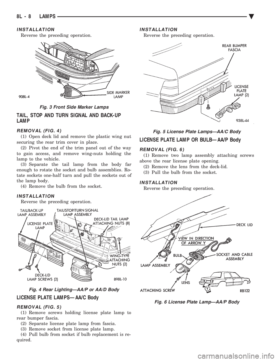
TAIL, STOP AND TURN SIGNAL AND BACK-UP
LAMP
REMOVAL (FIG. 4)
(1) Open deck lid and remove the plastic wing nut
securing the rear trim cover in place. (2) Pivot the end of the trim panel out of the way
to gain access, and remove wing-nuts holding the
lamp to the vehicle. (3) Separate the tail lamp from the body far
enough to rotate the socket and bulb assemblies. Ro-
tate sockets one-half turn and pull the sockets out of
the lamp body. (4) Remove the bulb from the socket.
INSTALLATION
Reverse the preceding operation.
LICENSE PLATE LAMPSÐAA/C Body
REMOVAL (FIG. 5)
(1) Remove screws holding license plate lamp to
rear bumper fascia. (2) Separate license plate lamp from fascia.
(3) Remove socket from license plate lamp.
(4) Pull bulb from socket if bulb replacement is re-
quired.
INSTALLATION
Reverse the preceding operation.
LICENSE PLATE LAMP OR BULBÐAA/P Body
REMOVAL (FIG. 6)
(1) Remove two lamp assembly attaching screws
above the rear license plate opening. (2) Remove the lens from the deck-lid.
(3) Pull the bulb from the socket.
INSTALLATION
Reverse the preceding operation.
Fig. 3 Front Side Marker Lamps
Fig. 4 Rear LightingÐAA/P or AA/D Body
Fig. 5 License Plate LampsÐAA/C Body
Fig. 6 License Plate LampÐAA/P Body
8L - 8 LAMPS Ä
Page 652 of 2438
EXTERIOR LAMPSÐAC BODY INDEX
page page
Aero Headlamp Bulb ...................... 10
Aero Headlamp Housing ................... 11
Aero HeadlampsÐAC/D-Body ............... 10
Center High Mounted Stop Lamp (CHMSL) ..... 13
Center High-Mounted Stop Lamp (CHMSL) Bulb . 13
Cornering Lamp Assembly .................. 12
Cornering Lamp Bulb ..................... 12
Front Side Marker BulbÐAC/C-Body .......... 12
Front Side Marker LampÐAC/C-Body ......... 12
Headlamp Diagnosis ...................... 10 Headlamp Sealed BeamÐAC/C Body
......... 10
License Plate Lamp/Bulb ................... 13
Park/Turn Signal Lamp or BulbÐAC/C-Body .... 11
Park/Turn Signal Lamp or BulbÐAC/D-Body .... 11
Rear Side Marker Lamp BulbÐAC/C-Body ..... 13
Rear Side Marker LampÐAC/C-Body ......... 13
Tail, Stop, Turn Signal, Back-Up and Side Marker LampÐAC/D-Body ...................... 12
Tail, Stop, Turn Signal, Back-Up LampÐAC/C or AY/S-Body ............................ 12
HEADLAMP DIAGNOSIS
Refer to the Headlamp Diagnosis at the beginning of
this Group. Refer to Wiring Diagrams Manual for
circuit and component locations.
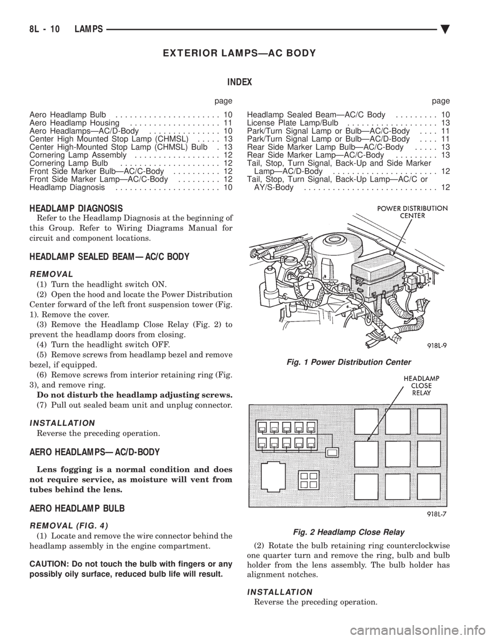
HEADLAMP SEALED BEAMÐAC/C BODY
REMOVAL
(1) Turn the headlight switch ON.
(2) Open the hood and locate the Power Distribution
Center forward of the left front suspension tower (Fig.
1). Remove the cover. (3) Remove the Headlamp Close Relay (Fig. 2) to
prevent the headlamp doors from closing. (4) Turn the headlight switch OFF.
(5) Remove screws from headlamp bezel and remove
bezel, if equipped. (6) Remove screws from interior retaining ring (Fig.
3), and remove ring. Do not disturb the headlamp adjusting screws.
(7) Pull out sealed beam unit and unplug connector.
INSTALLATION
Reverse the preceding operation.
AERO HEADLAMPSÐAC/D-BODY
Lens fogging is a normal condition and does
not require service, as moisture will vent from
tubes behind the lens.
AERO HEADLAMP BULB
REMOVAL (FIG. 4)
(1) Locate and remove the wire connector behind the
headlamp assembly in the engine compartment.
CAUTION: Do not touch the bulb with fingers or any
possibly oily surface, reduced bulb life will result. (2) Rotate the bulb retaining ring counterclockwise
one quarter turn and remove the ring, bulb and bulb
holder from the lens assembly. The bulb holder has
alignment notches.
INSTALLATION
Reverse the preceding operation.
Fig. 1 Power Distribution Center
Fig. 2 Headlamp Close Relay
8L - 10 LAMPS Ä
Page 653 of 2438
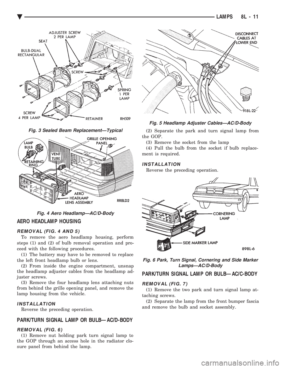
AERO HEADLAMP HOUSING
REMOVAL (FIG. 4 AND 5)
To remove the aero headlamp housing, perform
steps (1) and (2) of bulb removal operation and pro-
ceed with the following procedures. (1) The battery may have to be removed to replace
the left front headlamp bulb or lens. (2) From inside the engine compartment, unsnap
the headlamp adjuster cables from the headlamp ad-
juster screws. (3) Remove the four headlamp lens attaching nuts
from behind the grille opening panel, and remove the
lamp housing from the vehicle.
INSTALLATION
Reverse the preceding operation.
PARK/TURN SIGNAL LAMP OR BULBÐAC/D-BODY
REMOVAL (FIG. 6)
(1) Remove nut holding park turn signal lamp to
the GOP through an access hole in the radiator clo-
sure panel from behind the lamp. (2) Separate the park and turn signal lamp from
the GOP. (3) Remove the socket from the lamp
(4) Pull the bulb from the socket if bulb replace-
ment is required.
INSTALLATION
Reverse the preceding operation.
PARK/TURN SIGNAL LAMP OR BULBÐAC/C-BODY
REMOVAL (FIG. 7)
(1) Remove the two park and turn signal lamp at-
taching screws. (2) Separate the lamp from the front bumper fascia
and remove the bulb and socket assembly.
Fig. 3 Sealed Beam ReplacementÐTypical
Fig. 4 Aero HeadlampÐAC/D-Body
Fig. 5 Headlamp Adjuster CablesÐAC/D-Body
Fig. 6 Park, Turn Signal, Cornering and Side Marker LampsÐAC/D-Body
Ä LAMPS 8L - 11
Page 654 of 2438
INSTALLATION
Reverse the preceding operation.
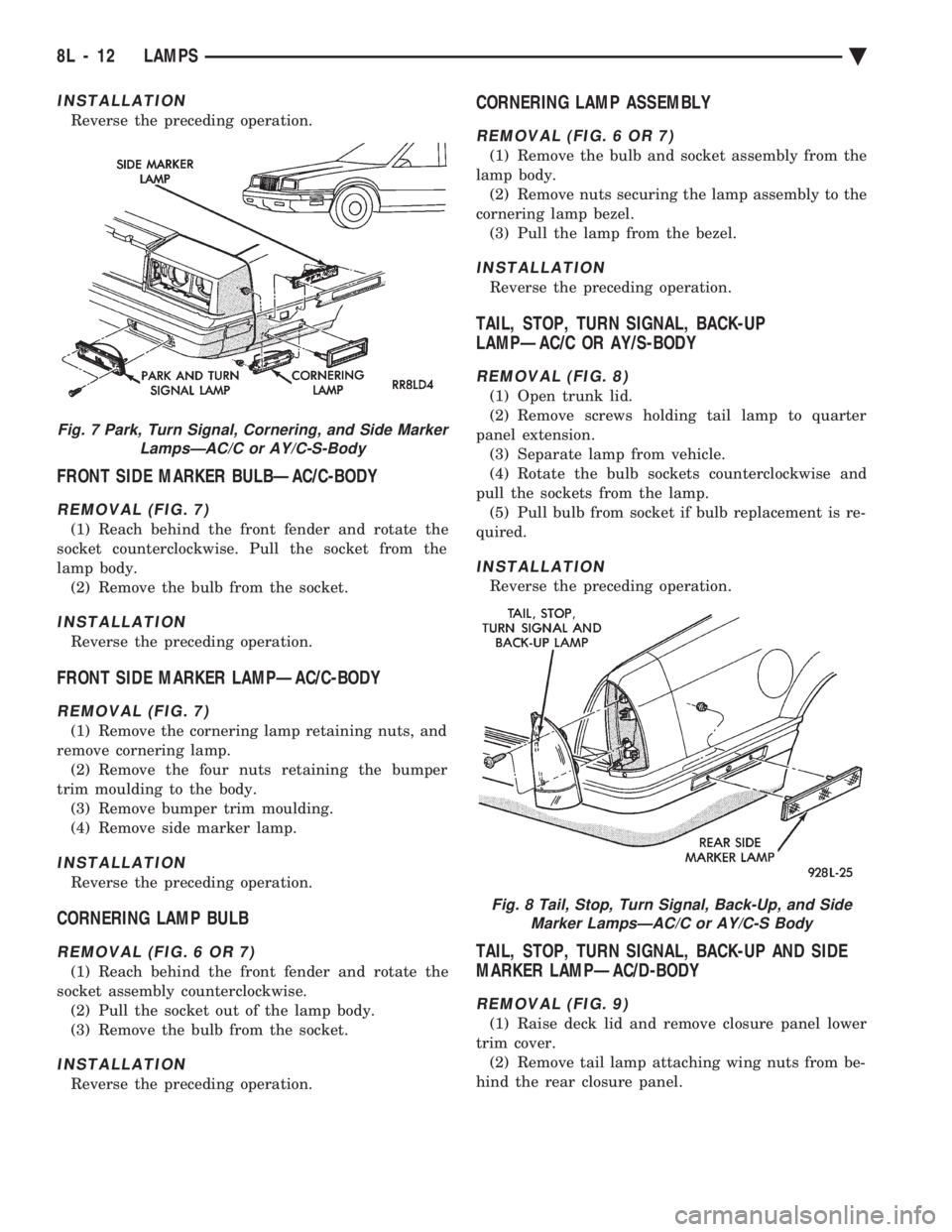
FRONT SIDE MARKER BULBÐAC/C-BODY
REMOVAL (FIG. 7)
(1) Reach behind the front fender and rotate the
socket counterclockwise. Pull the socket from the
lamp body. (2) Remove the bulb from the socket.
INSTALLATION
Reverse the preceding operation.
FRONT SIDE MARKER LAMPÐAC/C-BODY
REMOVAL (FIG. 7)
(1) Remove the cornering lamp retaining nuts, and
remove cornering lamp. (2) Remove the four nuts retaining the bumper
trim moulding to the body. (3) Remove bumper trim moulding.
(4) Remove side marker lamp.
INSTALLATION
Reverse the preceding operation.
CORNERING LAMP BULB
REMOVAL (FIG. 6 OR 7)
(1) Reach behind the front fender and rotate the
socket assembly counterclockwise. (2) Pull the socket out of the lamp body.
(3) Remove the bulb from the socket.
INSTALLATION
Reverse the preceding operation.
CORNERING LAMP ASSEMBLY
REMOVAL (FIG. 6 OR 7)
(1) Remove the bulb and socket assembly from the
lamp body. (2) Remove nuts securing the lamp assembly to the
cornering lamp bezel. (3) Pull the lamp from the bezel.
INSTALLATION
Reverse the preceding operation.
TAIL, STOP, TURN SIGNAL, BACK-UP
LAMPÐAC/C OR AY/S-BODY
REMOVAL (FIG. 8)
(1) Open trunk lid.
(2) Remove screws holding tail lamp to quarter
panel extension. (3) Separate lamp from vehicle.
(4) Rotate the bulb sockets counterclockwise and
pull the sockets from the lamp. (5) Pull bulb from socket if bulb replacement is re-
quired.
INSTALLATION
Reverse the preceding operation.
TAIL, STOP, TURN SIGNAL, BACK-UP AND SIDE
MARKER LAMPÐAC/D-BODY
REMOVAL (FIG. 9)
(1) Raise deck lid and remove closure panel lower
trim cover. (2) Remove tail lamp attaching wing nuts from be-
hind the rear closure panel.
Fig. 7 Park, Turn Signal, Cornering, and Side Marker LampsÐAC/C or AY/C-S-Body
Fig. 8 Tail, Stop, Turn Signal, Back-Up, and SideMarker LampsÐAC/C or AY/C-S Body
8L - 12 LAMPS Ä
Page 656 of 2438
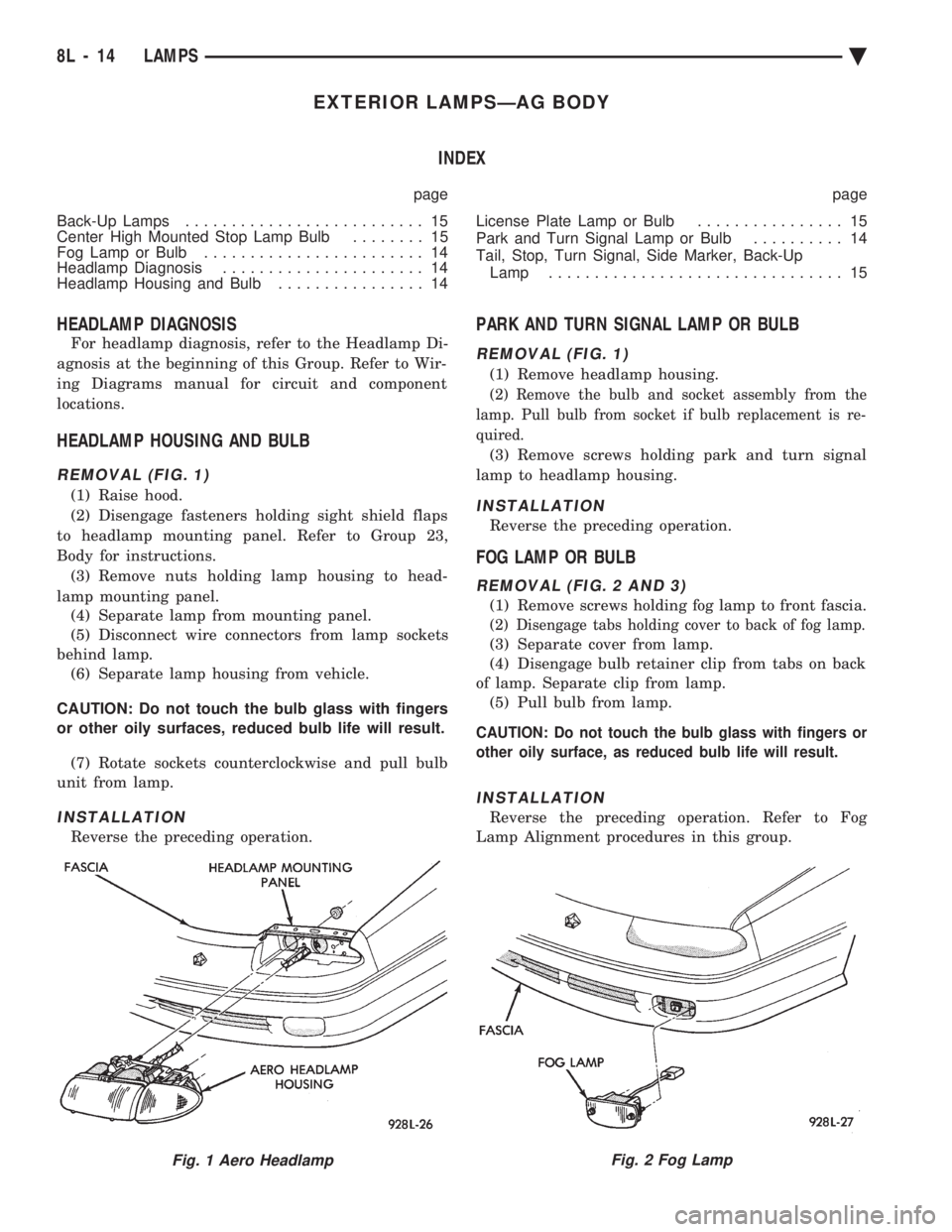
EXTERIOR LAMPSÐAG BODY INDEX
page page
Back-Up Lamps .......................... 15
Center High Mounted Stop Lamp Bulb ........ 15
Fog Lamp or Bulb ........................ 14
Headlamp Diagnosis ...................... 14
Headlamp Housing and Bulb ................ 14 License Plate Lamp or Bulb
................ 15
Park and Turn Signal Lamp or Bulb .......... 14
Tail, Stop, Turn Signal, Side Marker, Back-Up Lamp ................................ 15
HEADLAMP DIAGNOSIS
For headlamp diagnosis, refer to the Headlamp Di-
agnosis at the beginning of this Group. Refer to Wir-
ing Diagrams manual for circuit and component
locations.
HEADLAMP HOUSING AND BULB
REMOVAL (FIG. 1)
(1) Raise hood.
(2) Disengage fasteners holding sight shield flaps
to headlamp mounting panel. Refer to Group 23,
Body for instructions. (3) Remove nuts holding lamp housing to head-
lamp mounting panel. (4) Separate lamp from mounting panel.
(5) Disconnect wire connectors from lamp sockets
behind lamp. (6) Separate lamp housing from vehicle.
CAUTION: Do not touch the bulb glass with fingers
or other oily surfaces, reduced bulb life will result. (7) Rotate sockets counterclockwise and pull bulb
unit from lamp.
INSTALLATION
Reverse the preceding operation.
PARK AND TURN SIGNAL LAMP OR BULB
REMOVAL (FIG. 1)
(1) Remove headlamp housing.
(2) Remove the bulb and socket assembly from the
lamp. Pull bulb from socket if bulb replacement is re-
quired.
(3) Remove screws holding park and turn signal
lamp to headlamp housing.
INSTALLATION
Reverse the preceding operation.
FOG LAMP OR BULB
REMOVAL (FIG. 2 AND 3)
(1) Remove screws holding fog lamp to front fascia.
(2) Disengage tabs holding cover to back of fog lamp.
(3) Separate cover from lamp.
(4) Disengage bulb retainer clip from tabs on back
of lamp. Separate clip from lamp. (5) Pull bulb from lamp.
CAUTION: Do not touch the bulb glass with fingers or
other oily surface, as reduced bulb life will result.
INSTALLATION
Reverse the preceding operation. Refer to Fog
Lamp Alignment procedures in this group.
Fig. 1 Aero HeadlampFig. 2 Fog Lamp
8L - 14 LAMPS Ä
Page 657 of 2438
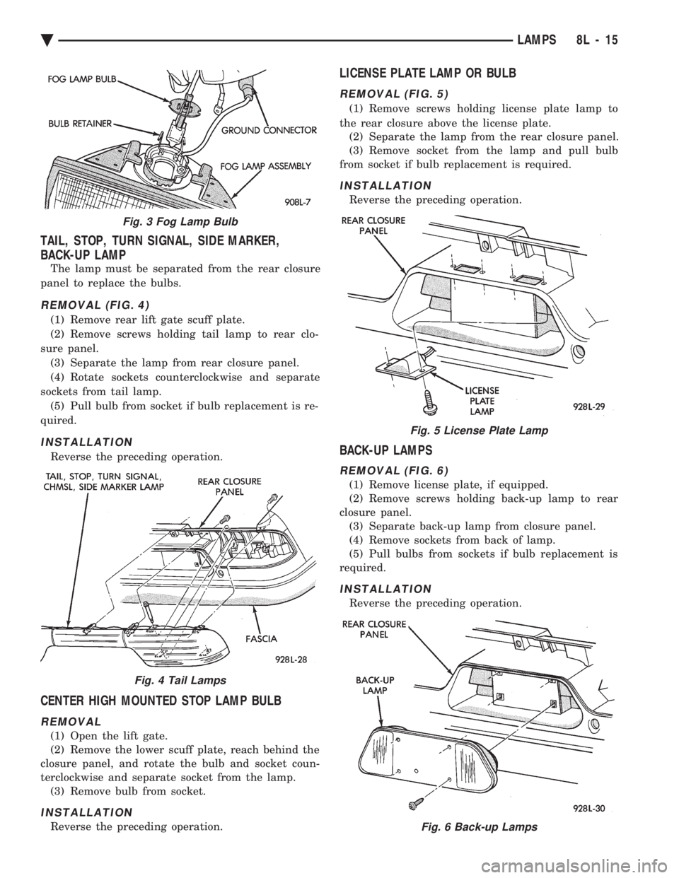
TAIL, STOP, TURN SIGNAL, SIDE MARKER,
BACK-UP LAMP
The lamp must be separated from the rear closure
panel to replace the bulbs.
REMOVAL (FIG. 4)
(1) Remove rear lift gate scuff plate.
(2) Remove screws holding tail lamp to rear clo-
sure panel. (3) Separate the lamp from rear closure panel.
(4) Rotate sockets counterclockwise and separate
sockets from tail lamp. (5) Pull bulb from socket if bulb replacement is re-
quired.
INSTALLATION
Reverse the preceding operation.
CENTER HIGH MOUNTED STOP LAMP BULB
REMOVAL
(1) Open the lift gate.
(2) Remove the lower scuff plate, reach behind the
closure panel, and rotate the bulb and socket coun-
terclockwise and separate socket from the lamp. (3) Remove bulb from socket.
INSTALLATION
Reverse the preceding operation.
LICENSE PLATE LAMP OR BULB
REMOVAL (FIG. 5)
(1) Remove screws holding license plate lamp to
the rear closure above the license plate. (2) Separate the lamp from the rear closure panel.
(3) Remove socket from the lamp and pull bulb
from socket if bulb replacement is required.
INSTALLATION
Reverse the preceding operation.
BACK-UP LAMPS
REMOVAL (FIG. 6)
(1) Remove license plate, if equipped.
(2) Remove screws holding back-up lamp to rear
closure panel. (3) Separate back-up lamp from closure panel.
(4) Remove sockets from back of lamp.
(5) Pull bulbs from sockets if bulb replacement is
required.
INSTALLATION
Reverse the preceding operation.
Fig. 3 Fog Lamp Bulb
Fig. 4 Tail Lamps
Fig. 5 License Plate Lamp
Fig. 6 Back-up Lamps
Ä LAMPS 8L - 15