change wheel CHEVROLET PLYMOUTH ACCLAIM 1993 User Guide
[x] Cancel search | Manufacturer: CHEVROLET, Model Year: 1993, Model line: PLYMOUTH ACCLAIM, Model: CHEVROLET PLYMOUTH ACCLAIM 1993Pages: 2438, PDF Size: 74.98 MB
Page 89 of 2438
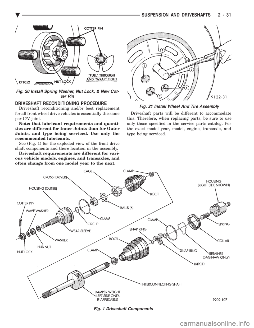
DRIVESHAFT RECONDITIONING PROCEDURE
Driveshaft reconditioning and/or boot replacement
for all front wheel drive vehicles is essentially the same
per C/V joint. Note: that lubricant requirements and quanti-
ties are different for Inner Joints than for Outer
Joints, and type being serviced. Use only the
recommended lubricants. See (Fig. 1) for the exploded view of the front drive
shaft components and there location in the assembly. Driveshaft requirements are different for vari-
ous vehicle models, engines, and transaxles, and
often change from one model year to the next. Driveshaft parts will be different to accommodate
this. Therefore, when replacing parts, be sure to use
only those specified in the service parts catalog. For
the exact model year, model, engine, transaxle, and
type being serviced.
Fig. 1 Driveshaft Components
Fig. 21 Install Wheel And Tire Assembly
Fig. 20 Install Spring Washer, Nut Lock, & New Cot- ter Pin
Ä SUSPENSION AND DRIVESHAFTS 2 - 31
Page 109 of 2438
to the road surface. While being able to twist as one
wheel moves vertically with respect to the other.Roll resistance is provided partly by the axle's re-
sistance to twist. But primarily by a torque tube or
rod (depending on the suspension option called for)
running through the channel and attached rigidly to
its end plates by welding. Because the torque tube/
rod is an integral part of the axle assembly, it cannot
be individually replaced. The spindles are bolted to the axle end (spindle
mounting) plates and can be individually replaced if
required. Rear wheel alignment changes require the
use of shims between the spindle and axle end plates.
SHOCK ABSORBERS
REMOVAL
(1) Raise vehicle, see Hoisting, Group 0.
(2) Support axle and remove wheel and tire assem-
bly. (3) If equipped with air shocks, disconnect air
lines. (4) Remove upper and lower shock absorber fasten-
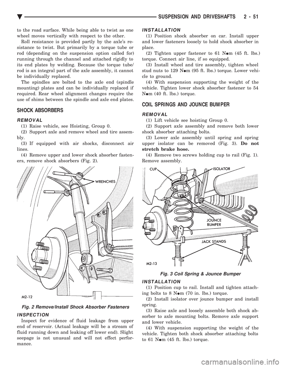
ers, remove shock absorbers (Fig. 2).
INSPECTION
Inspect for evidence of fluid leakage from upper
end of reservoir. (Actual leakage will be a stream of
fluid running down and leaking off lower end). Slight
seepage is not unusual and will not effect perfor-
mance.
INSTALLATION
(1) Position shock absorber on car. Install upper
and lower fasteners loosely to hold shock absorber in
place. (2) Tighten upper fastener to 61 N Im (45 ft. lbs.)
torque. Connect air line, if so equipped. (3) Install wheel and tire assembly, tighten wheel
stud nuts to 129 N Im (95 ft. lbs.) torque. Lower vehi-
cle to ground. (4) With suspension supporting the weight of the
vehicle. Tighten lower shock absorber fastener to 54
N Im (40 ft. lbs.) torque.
COIL SPRINGS AND JOUNCE BUMPER
REMOVAL
(1) Lift vehicle see hoisting Group 0.
(2) Support axle assembly and remove both lower
shock absorber attaching bolts. (3) Lower axle assembly until spring and spring
upper isolator can be removed (Fig. 3). Do not
stretch brake hose. (4) Remove two screws holding cup to rail (Fig. 1).
Remove assembly.
INSTALLATION
(1) Position cup to rail. Install and tighten attach-
ing bolts to 8 N Im (70 in. lbs.) torque.
(2) Install isolator over jounce bumper and install
spring. (3) Raise axle and loosely assemble both shock ab-
sorber to axle mounting bolts. Remove axle support
and lower vehicle. (4) With suspension supporting the weight of the
vehicle. Tighten both shock absorber attaching bolts
to 61 N Im (45 ft. lbs.) torque.
Fig. 2 Remove/Install Shock Absorber Fasteners
Fig. 3 Coil Spring & Jounce Bumper
Ä SUSPENSION AND DRIVESHAFTS 2 - 51
Page 147 of 2438
REAR (STUB) AXLE ALIGNMENT ALL MODELS INDEX
page page
General Information ....................... 89 Rear Wheel Alignment..................... 89
GENERAL INFORMATION
Because front wheel drive vehicles are equipped with
rear suspension incorporating stub axles (or wheel
spindles). It is possible to align both the camber and toe
of the rear wheels.
REAR WHEEL ALIGNMENT
Alignment adjustment if required. Is made by adding
0.010 inch shims (from the service package kit) be-
tween the spindle mounting surface and axle mounting
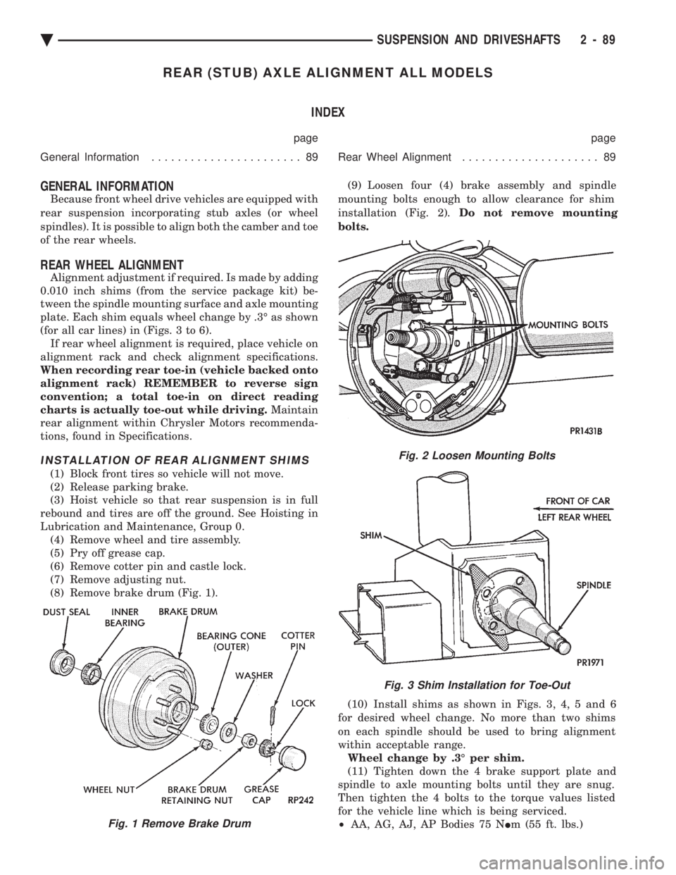
plate. Each shim equals wheel change by .3É as shown
(for all car lines) in (Figs. 3 to 6). If rear wheel alignment is required, place vehicle on
alignment rack and check alignment specifications.
When recording rear toe-in (vehicle backed onto
alignment rack) REMEMBER to reverse sign
convention; a total toe-in on direct reading
charts is actually toe-out while driving. Maintain
rear alignment within Chrysler Motors recommenda-
tions, found in Specifications.
INSTALLATION OF REAR ALIGNMENT SHIMS
(1) Block front tires so vehicle will not move.
(2) Release parking brake.
(3) Hoist vehicle so that rear suspension is in full
rebound and tires are off the ground. See Hoisting in
Lubrication and Maintenance, Group 0. (4) Remove wheel and tire assembly.
(5) Pry off grease cap.
(6) Remove cotter pin and castle lock.
(7) Remove adjusting nut.
(8) Remove brake drum (Fig. 1). (9) Loosen four (4) brake assembly and spindle
mounting bolts enough to allow clearance for shim
installation (Fig. 2). Do not remove mounting
bolts.
(10) Install shims as shown in Figs. 3, 4, 5 and 6
for desired wheel change. No more than two shims
on each spindle should be used to bring alignment
within acceptable range. Wheel change by .3É per shim.
(11) Tighten down the 4 brake support plate and
spindle to axle mounting bolts until they are snug.
Then tighten the 4 bolts to the torque values listed
for the vehicle line which is being serviced.
² AA, AG, AJ, AP Bodies 75 N Im (55 ft. lbs.)
Fig. 2 Loosen Mounting Bolts
Fig. 3 Shim Installation for Toe-Out
Fig. 1 Remove Brake Drum
Ä SUSPENSION AND DRIVESHAFTS 2 - 89
Page 151 of 2438
BRAKES
CONTENTS
page page
ANTI-LOCK BRAKE SYSTEMÐBENDIX ANTI-LOCK 10 AC/Y BODY ............. 72
ANTI-LOCK BRAKE SYSTEMÐBENDIX ANTI-LOCK 6 AA,AG,AJ,AP BODY ....... 113
BRAKE DISC (ROTOR) ................... 53
BRAKE SUPPORT ASSEMBLY ............. 25
FRONT DISC BRAKES ................... 31
GENERAL INFORMATION .................. 1
HYDRAULIC SYSTEM CONTROL VALVES . . . 26
KELSEY HAYES DOUBLE PIN FAMILY CALIPER ............................ 35 KELSEY HAYES DOUBLE PIN NON-FAMILY
CALIPER ............................ 38
MASTER CYLINDER ..................... 66
PARKING BRAKES ...................... 57
POWER BRAKES ....................... 68
REAR DISC BRAKES .................... 45
REAR WHEEL DRUM BRAKES ............ 18
SERVICE ADJUSTMENTS .................. 4
WHEEL BEARINGS ...................... 70
WHEEL CYLINDERS ..................... 23
GENERAL INFORMATION
Throughout this group, references may be made to
a particular vehicle by letter or number designation.
A chart showing the break down of these designa-
tions is included in the Introduction Section at the
front of this service manual. Standard brake equipment consists of:
² Double pin floating caliper disc front brakes.
² Rear automatic adjusting drum brakes.
² Differential valve with a brake warning switch.
² Master cylinder.
² Vacuum power booster.
² Double pin floating caliper rear disc brakes are
available on some models. The Bendix Anti-Lock 10 braking system, uses the
standard power brake system caliper assemblies,
braking discs, pedal assembly, brake lines and hoses.
The unique parts of the Bendix Anti-Lock 10 braking
system consists of the following components. Propor-
tioning valves, wheel speed sensors, tone wheels,
electronic control unit, modulator assembly and hy-
draulic assembly. These components replace the con-
ventional master cylinder and power booster. The
components will be described in detail in the Bendix
Anti-Lock 10 brake section in this group of the ser-
vice manual. The Bendix Anti-Lock 6 braking system, uses the
following standard brake system components. Master
cylinder, power booster, caliper assemblies, braking
discs, pedal assembly, brake lines and hoses. The
unique parts of the Bendix Anti-Lock 6 braking sys-
tem consists of the following components. Modulator
assembly, unique proportioning valves, wheel speed
sensors, tone wheels, and electronic control unit.
These components will be described in detail in the
Bendix Anti-Lock 6 brake section in this group of the
service manual. The front disc brake shoes have semi-metallic lin-
ings. The hydraulic brake system (Fig .123and4)is
diagonally split on both the Non-ABS and ABS brak-
ing system. With the left front and right rear brakes
on one hydraulic system and the right front and left
rear on the other. The Non-ABS and ABS brake system may use dif-
ferent types of brake line fittings and tubing flares.
The Non-ABS brake system uses double wall tubing
flares and fittings at all tubing joint locations. Some
ABS brake systems use both ISO style tubing flares
and double wall tubing flares and corresponding fit-
tings at different joint locations. See (Figs . 2 3 and 4)
for specific joint locations and type of tubing flare. The front disc brakes consist of two different types
of caliper assemblies. A double pin Kelsey-Hayes cal-
iper (family caliper) with a bolt-on adapter attached
to the steering knuckle. Or a double pin Kelsey-
Hayes caliper (non-family caliper) which mounts di-
rectly to rails on the steering knuckle. The non-
family caliper is only used on the AY Body
(Imperials).
CAUTION: Caliper pistons, boots and seals for the
different caliper assemblies used on the front and
rear disc brake assemblies are not interchangeable.
Misusage could result in a complete brake system
failure. Be sure that the parts are replaced with the
correct replacement parts, refer to the parts book
for the type and model year of the vehicle being
worked on.
The master cylinder is anodized, lightweight alu-
minum, with a bore size of 24.0mm, 21.0mm or 7/8
inch.
Ä BRAKES 5 - 1
Page 154 of 2438
SERVICE ADJUSTMENTS INDEX
page page
Adjusting Rear Service Brakes ............... 4
Bleeding Brake System ..................... 6
Brake Hose and Tubing ................... 11
Master Cylinder Fluid Level .................. 4 Stop Lamp Switch Adjustment (All Vehicles)
.... 13
Test for Fluid Contamination ................. 7
Testing Application Adjuster Operation ......... 6
Wheel Stud Nut Tightening .................. 7
MASTER CYLINDER FLUID LEVEL
ALL EXCEPT AC/AY BODY WITH ABS
Check master cylinder reservoir brake fluid level a
minimum of twice a year. Master cylinder reservoirs are marked with the
words fill to bottom of rings indicating proper fluid
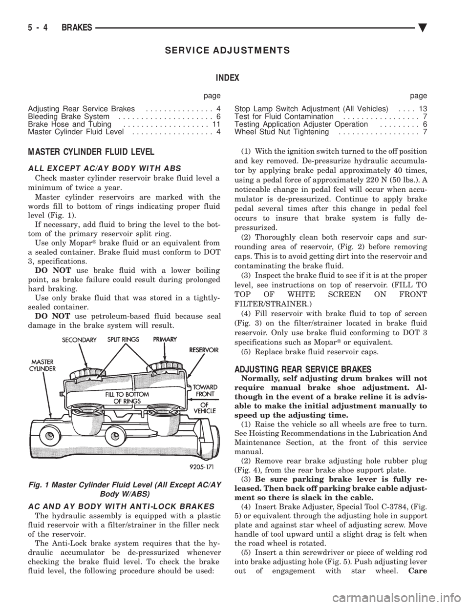
level (Fig. 1). If necessary, add fluid to bring the level to the bot-
tom of the primary reservoir split ring. Use only Mopar tbrake fluid or an equivalent from
a sealed container. Brake fluid must conform to DOT
3, specifications. DO NOT use brake fluid with a lower boiling
point, as brake failure could result during prolonged
hard braking. Use only brake fluid that was stored in a tightly-
sealed container. DO NOT use petroleum-based fluid because seal
damage in the brake system will result.
AC AND AY BODY WITH ANTI-LOCK BRAKES
The hydraulic assembly is equipped with a plastic
fluid reservoir with a filter/strainer in the filler neck
of the reservoir. The Anti-Lock brake system requires that the hy-
draulic accumulator be de-pressurized whenever
checking the brake fluid level. To check the brake
fluid level, the following procedure should be used: (1) With the ignition switch turned to the off position
and key removed. De-pressurize hydraulic accumula-
tor by applying brake pedal approximately 40 times,
using a pedal force of approximately 220 N (50 lbs.). A
noticeable change in pedal feel will occur when accu-
mulator is de-pressurized. Continue to apply brake
pedal several times after this change in pedal feel
occurs to insure that brake system is fully de-
pressurized. (2) Thoroughly clean both reservoir caps and sur-
rounding area of reservoir, (Fig. 2) before removing
caps. This is to avoid getting dirt into the reservoir and
contaminating the brake fluid. (3) Inspect the brake fluid to see if it is at the proper
level, see instructions on top of reservoir. (FILL TO
TOP OF WHITE SCREEN ON FRONT
FILTER/STRAINER.) (4) Fill reservoir with brake fluid to top of screen
(Fig. 3) on the filter/strainer located in brake fluid
reservoir. Only use brake fluid conforming to DOT 3
specifications such as Mopar tor equivalent.
(5) Replace brake fluid reservoir caps.
ADJUSTING REAR SERVICE BRAKES
Normally, self adjusting drum brakes will not
require manual brake shoe adjustment. Al-
though in the event of a brake reline it is advis-
able to make the initial adjustment manually to
speed up the adjusting time. (1) Raise the vehicle so all wheels are free to turn.
See Hoisting Recommendations in the Lubrication And
Maintenance Section, at the front of this service
manual. (2) Remove rear brake adjusting hole rubber plug
(Fig. 4), from the rear brake shoe support plate. (3) Be sure parking brake lever is fully re-
leased. Then back off parking brake cable adjust-
ment so there is slack in the cable. (4) Insert Brake Adjuster, Special Tool C-3784, (Fig.
5) or equivalent through the adjusting hole in support
plate and against star wheel of adjusting screw. Move
handle of tool upward until a slight drag is felt when
the road wheel is rotated. (5) Insert a thin screwdriver or piece of welding rod
into brake adjusting hole (Fig. 5). Push adjusting lever
out of engagement with star wheel. Care
Fig. 1 Master Cylinder Fluid Level (All Except AC/AY
Body W/ABS)
5 - 4 BRAKES Ä
Page 161 of 2438
BRAKE HOSE AND TUBING
INSPECTION OF BRAKE HOSE AND TUBING
Flexible rubber hose is used at both front brakes and
at the rear axle. Inspection of brake hoses should be
performed whenever the brake system is serviced and
every 7,500 miles or 12 months, whichever comes first
(every engine oil change). Inspect hydraulic brake
hoses for severe surface cracking, scuffing, or worn
spots. Should the fabric casing of the rubber hose be
exposed due to cracks or abrasions in the rubber hose
cover, the hose should be replaced immediately. Even-
tual deterioration of the hose can take place with
possible burst failure. Faulty installation can cause
twisting and wheel, tire or chassis interference. The steel brake tubing should be inspected periodi-
cally for evidence of physical damage or contact with
moving or hot components.
INSTALLATION OF BRAKE HOSE
Always use factory recommended brake hose to en-
sure quality, correct length and superior fatigue life.
Care should be taken to make sure that the tube and
hose mating surfaces are clean and free from nicks and
burrs. Front right and left side hoses are not
interchangeable. Connections should be correct and properly made.
Use new copper seal washers on all connections using
Banjo Bolts and tighten all fittings to their specified
torques. The flexible front hydraulic brake hose should al-
ways be installed on the vehicle by first attaching the
Banjo connector to the caliper assembly. Then bolt the
intermediate hose bracket to the strut assembly allow-
ing the bracket to position the hose to prevent twisting.
Attach the hose to the body bracket and steel brake
tubing. Tighten all fittings to specified torque. The
body bracket and hose end are keyed so that they will
only fit one way. Install rear brake hoses first to the trailing arm
tubes and then to the floor pan tubes. Minimize hose
twisting. Vehicles equipped with rear disc brakes have
brake hoses attached to the caliper on each side. The
brake hose should be first attached by the Banjo bolt to
the caliper and then secured to the hose bracket with
the retaining clip. The attach the steel brake tubing to
the hose fitting.
REPAIR AND INSTALLATION OF BRAKE TUB- ING
Only double wall 4.75mm (3/16 in.) steel tubing
should be used for replacement. Care should be taken
when replacing brake tubing, to be sure the proper
bending and flaring tools and procedures are used, to
avoid kinking. Do not route the tubes against sharp edges, moving components or into hot areas. All
tubes should be properly attached with recommended
retaining clips.
TYPES OF TUBING FLARES
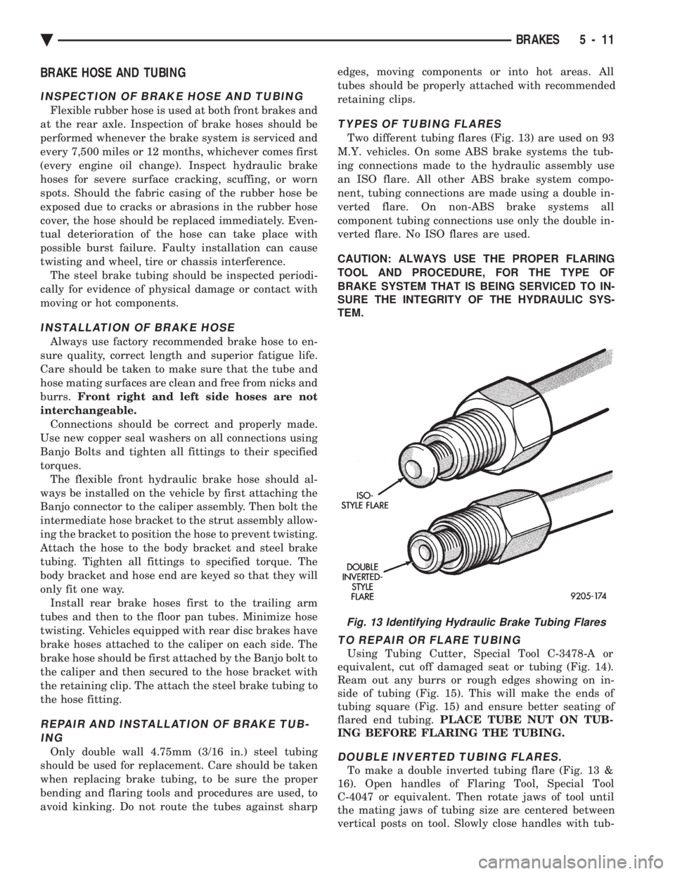
Two different tubing flares (Fig. 13) are used on 93
M.Y. vehicles. On some ABS brake systems the tub-
ing connections made to the hydraulic assembly use
an ISO flare. All other ABS brake system compo-
nent, tubing connections are made using a double in-
verted flare. On non-ABS brake systems all
component tubing connections use only the double in-
verted flare. No ISO flares are used.
CAUTION: ALWAYS USE THE PROPER FLARING
TOOL AND PROCEDURE, FOR THE TYPE OF
BRAKE SYSTEM THAT IS BEING SERVICED TO IN-
SURE THE INTEGRITY OF THE HYDRAULIC SYS-
TEM.
TO REPAIR OR FLARE TUBING
Using Tubing Cutter, Special Tool C-3478-A or
equivalent, cut off damaged seat or tubing (Fig. 14).
Ream out any burrs or rough edges showing on in-
side of tubing (Fig. 15). This will make the ends of
tubing square (Fig. 15) and ensure better seating of
flared end tubing. PLACE TUBE NUT ON TUB-
ING BEFORE FLARING THE TUBING.
DOUBLE INVERTED TUBING FLARES.
To make a double inverted tubing flare (Fig. 13 &
16). Open handles of Flaring Tool, Special Tool
C-4047 or equivalent. Then rotate jaws of tool until
the mating jaws of tubing size are centered between
vertical posts on tool. Slowly close handles with tub-
Fig. 13 Identifying Hydraulic Brake Tubing Flares
Ä BRAKES 5 - 11
Page 171 of 2438
If old springs have overheated or are damaged, re-
place. Overheating indications are paint discoloration
or distorted end coils. Varga brake springs are not
painted but overheating of the brake springs will be
noted by any Blueing of the springs.
BRAKE SHOE INSTALLATION
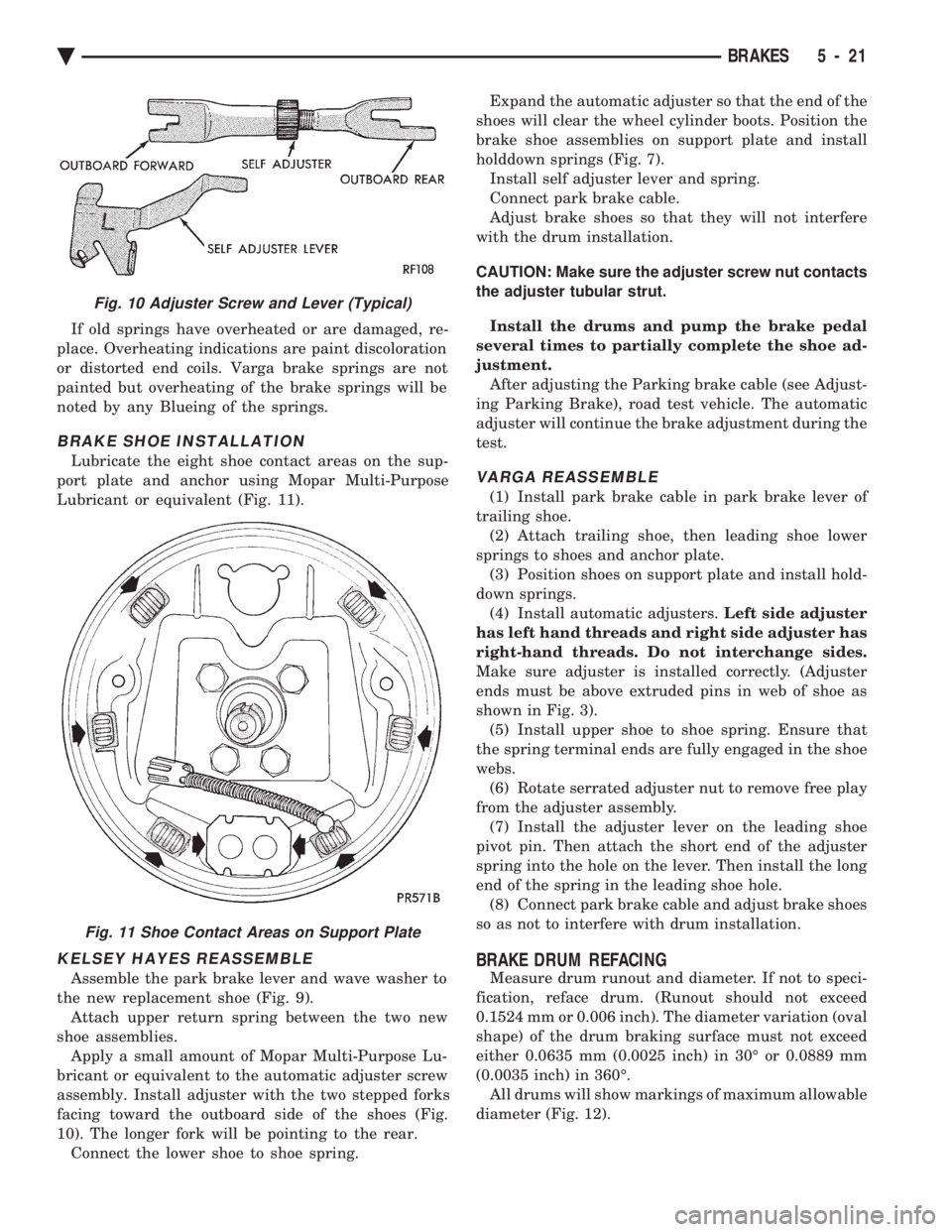
Lubricate the eight shoe contact areas on the sup-
port plate and anchor using Mopar Multi-Purpose
Lubricant or equivalent (Fig. 11).
KELSEY HAYES REASSEMBLE
Assemble the park brake lever and wave washer to
the new replacement shoe (Fig. 9). Attach upper return spring between the two new
shoe assemblies. Apply a small amount of Mopar Multi-Purpose Lu-
bricant or equivalent to the automatic adjuster screw
assembly. Install adjuster with the two stepped forks
facing toward the outboard side of the shoes (Fig.
10). The longer fork will be pointing to the rear. Connect the lower shoe to shoe spring. Expand the automatic adjuster so that the end of the
shoes will clear the wheel cylinder boots. Position the
brake shoe assemblies on support plate and install
holddown springs (Fig. 7). Install self adjuster lever and spring.
Connect park brake cable.
Adjust brake shoes so that they will not interfere
with the drum installation.
CAUTION: Make sure the adjuster screw nut contacts
the adjuster tubular strut.
Install the drums and pump the brake pedal
several times to partially complete the shoe ad-
justment. After adjusting the Parking brake cable (see Adjust-
ing Parking Brake), road test vehicle. The automatic
adjuster will continue the brake adjustment during the
test.
VARGA REASSEMBLE
(1) Install park brake cable in park brake lever of
trailing shoe. (2) Attach trailing shoe, then leading shoe lower
springs to shoes and anchor plate. (3) Position shoes on support plate and install hold-
down springs. (4) Install automatic adjusters. Left side adjuster
has left hand threads and right side adjuster has
right-hand threads. Do not interchange sides.
Make sure adjuster is installed correctly. (Adjuster
ends must be above extruded pins in web of shoe as
shown in Fig. 3). (5) Install upper shoe to shoe spring. Ensure that
the spring terminal ends are fully engaged in the shoe
webs. (6) Rotate serrated adjuster nut to remove free play
from the adjuster assembly. (7) Install the adjuster lever on the leading shoe
pivot pin. Then attach the short end of the adjuster
spring into the hole on the lever. Then install the long
end of the spring in the leading shoe hole. (8) Connect park brake cable and adjust brake shoes
so as not to interfere with drum installation.
BRAKE DRUM REFACING
Measure drum runout and diameter. If not to speci-
fication, reface drum. (Runout should not exceed
0.1524 mm or 0.006 inch). The diameter variation (oval
shape) of the drum braking surface must not exceed
either 0.0635 mm (0.0025 inch) in 30É or 0.0889 mm
(0.0035 inch) in 360É. All drums will show markings of maximum allowable
diameter (Fig. 12).
Fig. 10 Adjuster Screw and Lever (Typical)
Fig. 11 Shoe Contact Areas on Support Plate
Ä BRAKES 5 - 21
Page 239 of 2438
Brake Warning Lamp may indicate reduced
braking ability. The following procedure should
be used to test drive an ABS complaint:(1) Ignition on. Turn the ignition to the ON position
without starting the car and wait until the Red Brake
Warning Lamp and Amber Anti-Lock Warning Lamp
turn off. This will allow the pump to charge the
accumulator to operating pressure. If the warning
lamp(s) do not turn off, go to step 3. (2) Ignition off for 15 seconds.
(3) Start car. Wait for displays to return to normal
operating mode before proceeding. (4) With Shift lever in PARK, slowly depress brake
pedal and release. (5) Drive vehicle a short distance. During this test
drive, be sure that the vehicle achieves at least 20 mph.
Then brake to at least one complete stop and accelerate
slowly back up to at least 20 mph. (6) If a functional problem with the A.B.S. system is
determined while test driving a vehicle. Refer to the
Bendix Anti-Lock 10 Diagnostics Manual for required
test procedures and proper use of the DRB II tester.
CAUTION: The following are general precautions that
should be observed when servicing and diagnosing
the ABS system and/or other vehicle systems. Failure
to observe these precautions may result in ABS
system damage.
(1) If welding work is to be performed on the vehicle
using an arc welder, the (CAB) should be disconnected
before the welding operation begins. (2) The (CAB) and hydraulic assembly 10 way con-
nectors should never be connected or disconnected with
the ignition on. (3) Some components of the ABS system are not
serviced separately and must be serviced as complete
assemblies. Do not disassemble any component which
is designated as non-serviceable. (4) Always de-pressurize the Hydraulic Accu-
mulator when performing any work that re-
quires disconnecting any hydraulic tube, flex
hose or fitting. The ABS system uses brake fluid
at high pressure. Failure to de-pressurize the
accumulator may result in personal injury
and/or damage to painted surfaces. Brake fluid will damage painted surfaces. If brake
fluid is spilled on any painted surfaces, wash off with
water immediately.
DE-PRESSURIZING HYDRAULIC ACCUMULA- TOR
The ABS pump/motor assembly keeps the hydraulic
accumulator charged between approximately 11,032
and 13,790 kPa (1600 and 2000 psi) anytime key is in the ON position. The pump/motor assembly
cannot run if the ignition is off or either battery ca-
ble is disconnected. Unless otherwise specified, the hydraulic accumu-
lator should be de-pressurized before disassembling
any portion of the hydraulic system. The following
procedure should be used to de-pressurize the hy-
draulic accumulator: (1) With ignition off, or either battery cable discon-
nected, pump the brake pedal a minimum of 40 times
using approximately 50 pounds of pedal force. A no-
ticeable change in pedal feel will occur when the ac-
cumulator becomes discharged. (2) When a definite increase in pedal effort is felt,
pump the pedal a few additional times. This will in-
sure removal of all hydraulic pressure from the
brake system.
WHEEL SPEED SENSOR CABLES
Proper installation of wheel speed sensor cables is
critical to continued ABS system operation. Be sure
that cables are installed and routed properly. Failure
to install cables in their retainers, as shown in Sec-
tion 3 of this manual. May result in contact with
moving parts or over extension of cables, resulting in
an open circuit.
MECHANICAL DIAGNOSTICS AND SERVICE
PROCEDURES
SPECIAL SERVICE TOOLS
Some diagnostic procedures in this section require
the use of special service tools. Each of these tools is
described below.
DRB II DIAGNOSTIC TESTER
Some of the diagnostic procedures that are ex-
plained in this section require the use of the DRB II
DIAGNOSTICS TESTER to insure that proper diag-
nostics are performed. Refer to those sections for
proper testing procedures and the DRB II manual for
its proper operational information.
MST-6163 PRESSURE TESTER
Some diagnostic procedures in this manual require
the use of the MST-6163 pressure gauge and adaptor
(Fig. 2). Pressure Gauge, Special Tool MST-6163 is
required to measure accumulator pressure during
certain phases of ABS operation. The pressure gauge
and adaptor should be installed as follows: (1) De-pressurize the accumulator by pumping the
brake pedal a minimum of 40 times with the ignition
off. The procedure is fully explained under De-Pres-
surizing Hydraulic Accumulator which is described
earlier in this System Diagnosis Section.
Ä ANTI-LOCK 10 BRAKE SYSTEM 5 - 89
Page 483 of 2438
(2) With engine running, move test probe along
entire length of all cables (approximately 0 to 1/8
inch gap). If punctures or cracks are present there
will be a noticeable spark jump from the faulty area
to the probe. Cracked, leaking or faulty cables should
be replaced. Use the following procedure when removing the
high tension cable from the spark plug. First, remove
the cable from the retaining bracket. Then grasp the
terminal as close as possible to the spark plug. Ro-
tate the cover (boot) slightly and pull straight back.
Do not use pliers and do not pull the cable at an
angle. Doing so will damage the insulation, cable
terminal or the spark plug insulator. Wipe spark
plug insulator clean before reinstalling cable
and cover. Resistance cables are identified by the words Elec-
tronic Suppression .
Use an ohmmeter to check cables for opens, loose
terminals or high resistance. (a) Remove cable from spark plug.
(b) Remove cable from the coil tower.
(c) Connect the ohmmeter between spark plug
end terminal and the coil end terminal. Resistance
should be within tolerance shown in the cable re-
sistance chart. If resistance is not within tolerance,
replace cable assembly. Test all spark plug cables
in same manner.
SPARK PLUG SERVICE
When replacing the spark plug cables, route the ca-
bles correctly and secure them in the appropriate re-
tainers. Incorrectly routed cables can cause the radio
to reproduce ignition noise. It can also cause cross ig-
nition of the spark plugs or short circuit the cables to
ground.
SPARK PLUG REMOVAL
Always remove cables by grasping at boot, rotating
the boot 1/2 turn, and pulling straight back in a
steady motion. (1) Prior to removing the spark plug spray com-
pressed air around the spark plug hole and the area
around the spark plug. (2) Remove the spark plug using a quality socket
with a rubber or foam insert. (3) Inspect the spark plug condition. Refer to
Spark Plug Condition in this section.
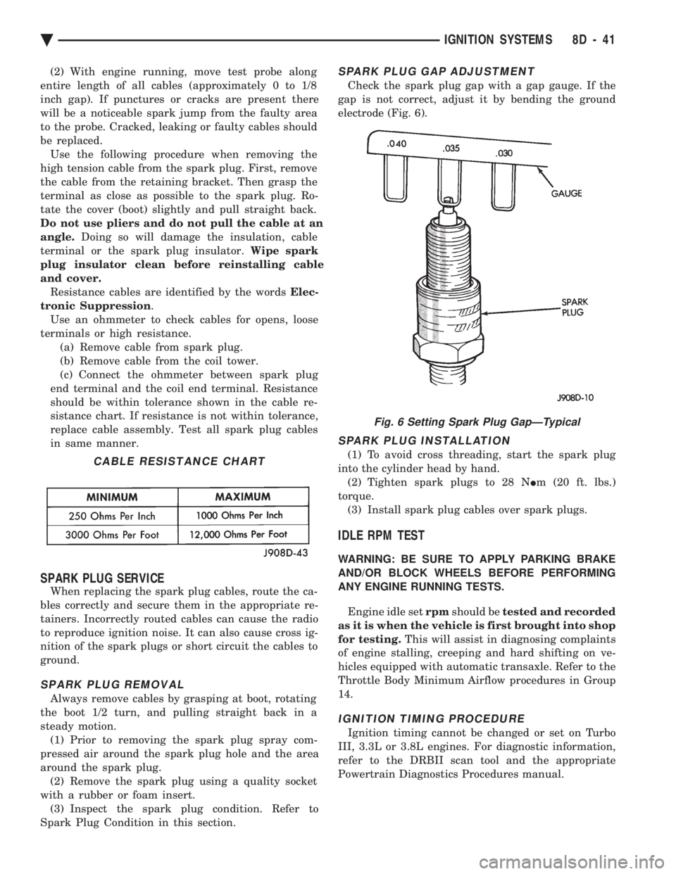
SPARK PLUG GAP ADJUSTMENT
Check the spark plug gap with a gap gauge. If the
gap is not correct, adjust it by bending the ground
electrode (Fig. 6).
SPARK PLUG INSTALLATION
(1) To avoid cross threading, start the spark plug
into the cylinder head by hand. (2) Tighten spark plugs to 28 N Im (20 ft. lbs.)
torque. (3) Install spark plug cables over spark plugs.
IDLE RPM TEST
WARNING: BE SURE TO APPLY PARKING BRAKE
AND/OR BLOCK WHEELS BEFORE PERFORMING
ANY ENGINE RUNNING TESTS.
Engine idle set rpmshould be tested and recorded
as it is when the vehicle is first brought into shop
for testing. This will assist in diagnosing complaints
of engine stalling, creeping and hard shifting on ve-
hicles equipped with automatic transaxle. Refer to the
Throttle Body Minimum Airflow procedures in Group
14.
IGNITION TIMING PROCEDURE
Ignition timing cannot be changed or set on Turbo
III, 3.3L or 3.8L engines. For diagnostic information,
refer to the DRBII scan tool and the appropriate
Powertrain Diagnostics Procedures manual.
CABLE RESISTANCE CHART
Fig. 6 Setting Spark Plug GapÐTypical
Ä IGNITION SYSTEMS 8D - 41
Page 613 of 2438
TURN SIGNALS AND HAZARD WARNING FLASHER
CONTENTS
page page
AG AND AJ BODIES ..................... 1
CHIME FUNCTIONÐAC, AG, AJ AND AY .... 1
DUAL-FUNCTION SWITCHÐAG AND AJ BODIES.5
GENERAL INFORMATION .................. 1
HAZARD WARNING SYSTEM .............. 1
MULTI-FUNCTION SWITCHÐAA, AC, AP AND AY BODIES .............................. 2 REMOTE TURN SIGNAL SWITCH REMOVALÐAG
AND AJ BODIES ....................... 5
TESTING PROCEDURES ................... 2
TURN SIGNAL AND HAZARD WARNING FLASHER LOCATION ............................ 6
TURN SIGNAL RELAYSÐAG AND AJ BODIES . 6
GENERAL INFORMATION
WARNING: ON VEHICLES EQUIPPED WITH AIR-
BAG, SEE GROUP 8M, RESTRAINT SYSTEMS FOR
AIRBAG REMOVAL PROCEDURES.
TURN SIGNALSÐAC, AY, AA AND AP BODIES
The turn signals are part of the multi-function switch.
Which contains electrical circuitry for turn signal, cor-
nering lamps, hazard warning, headlamp beam select,
headlamp optical horn, windshield wiper, pulse wipe
and windshield washer switching. The integrated switch
assembly is mounted to the left hand side of the steer-
ing column. When the driver wishes to signal his inten-
tions to change direction of travel, he moves the lever
upward to cause the right signals to flash and down-
ward to cause the left signals to flash. After completion
of a turn the system is deactivated automatically. As
the steering wheel returns to the straight ahead posi-
tion, a canceling cam of two lobes molded to the clock-
spring mechanism comes in contact with the cancel
actuator on the turn signal multi-function switch as-
sembly. Either cam lobe, pushing on the cancel actua-
tor, returns the switch to the off position. If only momentary signaling such as indication of a
lane change is desired, the switch is actuated to a left
or right intermediate detent position. In this position
the signal lamps flash as described above, but the
switch returns to the OFF position as soon as the lever
is released.
When the system is activated, 1 of 2 indicator
lamps mounted in the instrument cluster flashes in
unison with the turn signal lamps, indicating to the
driver that the system is operating.
AG AND AJ BODIES
The turn signals are actuated with lever on the left
side of the instrument panel switch pod. When the
driver wishes to signal his intentions to change di- rection of travel, he moves the lever upward to cause
the right signals to flash and downward to cause the
left signals to flash. After completion of a turn the system is deacti-
vated automatically. The cancellation switch in the
steering column sends a signal to a remote turn sig-
nal switch in the switch pod to cancel the turn signal
function. As the steering wheel returns to the
straight ahead position from a turn, a cancel cam
which is located on the steering wheel contacts a
cancel flipper located on the cancellation switch.
When the flipper is contacted by the cancel cam in
the proper rotational direction, the cancel switch
sends a signal to the remote turn signal switch. If only momentary signaling such as indication of a
lane change is desired, the switch is actuated to a
left or right intermediate detent position. In this po-
sition the signal lamps flash as described above, but
the switch returns to the OFF position as soon as the
lever is released. When the system is activated, 1 of 2 indicator
lamps mounted in the instrument cluster flashes in
unison with the turn signal lamps, indicating to the
driver that the system is operating.
HAZARD WARNING SYSTEM
The hazard warning system is actuated by a push
button located on the top of the steering column be-
tween the steering wheel and the instrument panel.
The hazard switch is identified with a double trian-
gle on top of the button. Push and release the button
to turn the hazard function ON or OFF. The button
will move out from the steering column in the ON
position and will remain in toward the column in the
OFF position.
CHIME FUNCTIONÐAC, AG, AJ AND AY
The chime will sound after the vehicle has traveled
a distance of 0.6 miles at a speed above 15 miles per
hour.
Ä TURN SIGNALS AND HAZARD WARNING FLASHER 8J - 1