change wheel CHEVROLET PLYMOUTH ACCLAIM 1993 Owner's Guide
[x] Cancel search | Manufacturer: CHEVROLET, Model Year: 1993, Model line: PLYMOUTH ACCLAIM, Model: CHEVROLET PLYMOUTH ACCLAIM 1993Pages: 2438, PDF Size: 74.98 MB
Page 2151 of 2438

ponents. Under extremes of suspension and steering
travel tire damage may occur.
WARNING: FAILURE TO EQUIP THE VEHICLE WITH
TIRES HAVING ADEQUATE SPEED RATING CAN
CAUSE SUDDEN TIRE FAILURE.
ROTATION
DIRECTIONAL TREAD PATTERN TIRES
Some vehicles are fitted with special high-perfor-
mance tires having a directional tread pattern de-
signed to improve traction on wet pavement. To obtain the full benefits of this design, the tires
must be installed so that they rotate in the correct
direction. This is indicated by arrows on the tire
sidewalls. When wheels and tires are being installed, extra
care is needed to ensure that this direction of rota-
tion is maintained. Refer to Owner's Manual for rotation schedule.
NONDIRECTIONAL TIRES
Tires on the front and rear axles of vehicles oper-
ate at different loads and perform different steering,
driving, and braking functions. For these reasons,
they wear at unequal rates, and tend to develop ir-
regular wear patterns. These effects can be reduced
by timely rotation of tires. Rotation will increase
tread life, help to maintain mud, snow, and wet trac-
tion levels, and contribute to a smooth, quiet ride. The suggested rotation method is the forward-cross
tire rotation method. This method takes advantage of
current tire industry practice which now allows cross
rotation of radial-ply tires. Refer to the owner's man-
ual (usually found in the glove box) for additional in-
formation. Other rotation methods may be used, but
may not have all the benefits of the recommended
method. Always check air pressure and wheel nut tightness
after rotation. Do NOT use oil or grease on studs
or nuts. Refer to Owner's Manual for rotation schedule.
TREAD WEAR INDICATORS
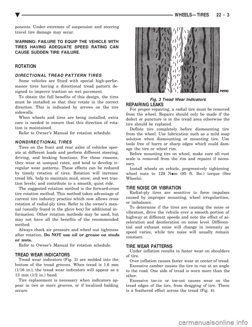
Tread wear indicators (Fig. 3) are molded into the
bottom of the tread grooves. When tread is 1.6 mm
(1/16 in.), the tread wear indicators will appear as a
13 mm (1/2 in.) band. Tire replacement is necessary when indicators ap-
pear in two or more grooves, or if localized balding
occurs.
REPAIRING LEAKS
For proper repairing, a radial tire must be removed
from the wheel. Repairs should only be made if the
defect or puncture is in the tread area otherwise the
tire should be replaced. Deflate tire completely before dismounting tire
from the wheel. Use lubrication such as a mild soap
solution when dismounting or mounting tire. Use
tools free of burrs or sharp edges which could dam-
age the tire or wheel rim. Before mounting tire on wheel, make sure all rust
scale is removed from the rim and repaint if neces-
sary. Install wheels on vehicle, progressively tightening
wheel nuts to 129 N Im (95 ft. lbs.) torque (See
Wheels).
TIRE NOISE OR VIBRATION
Radial-ply tires are sensitive to force impulses
caused by improper mounting, wheel irregularities,
or imbalance. To determine if the tires are causing the noise or
vibration, drive the vehicle over a smooth portion of
highway at different speeds and note the effect of ac-
celeration and deceleration on noise level. Differen-
tial and exhaust noise will change in intensity as
speed varies, while tire noise will usually remain
constant.
TIRE WEAR PATTERNS
Under inflation results in faster wear on shoulders
of tire. Over inflation causes faster wear at center of tread.
Excessive camber causes the tire to run at an angle
to the road. One side of tread is worn more than the
other. Excessive toe-in or toe-out causes wear on the
tread edges of the tire, from dragging of tire. There
is a feathered effect across the tread (Fig. 4).
Fig. 3 Tread Wear Indicators
Ä WHEELSÐTIRES 22 - 3
Page 2288 of 2438

(3) Loosen nuts holding roof rail weatherstrip re-
tainer to roof rail. Shift retainer inboard or outboard
to achieve proper alignment. (4) Tighten nuts to hold retainer to roof rail and
latch top header. (5) Verify weatherstrip sealing and door closing ef-
fort.
QUARTER GLASS AND ROLLER BRACKET
QUARTER GLASS
(1) Verify that door glass is properly aligned.
(2) Loosen nut holding top of quarter glass to rear
roof rail. (3) Shift quarter glass inboard or outboard, for-
ward or rearward to achieve proper alignment. (4) Tighten nut to hold top of quarter glass to rear
roof rail. (5) Verify door glass operation and weatherstrip
sealing.
ROLLER BRACKET
The roller bracket controls the in and out move-
ment at the bottom for the quarter glass. (1) Remove quarter trim panel as necessary to
gain access to the bottom of the quarter glass. (2) Lower convertible top.
(3) Loosen bolts holding roller bracket to quarter
panel reinforcement. (4) Align roller bracket to reduce quarter belt
weatherstrip contact when top is raised and proper
sash weatherstrip compression against the door
glass. (5) Tighten bolts to hold roller to quarter panel
and verify top operation and weatherstrip sealing.
TOP STACK DOWN-STOP
Adjust down-stop in or out to set top stack down
position height.
CAUTION: Avoid setting top stack position too low,
top cover can be pinched and cut between wheel-
house and fourth bow. Seal base of down-stop with silicone after adjust-
ing to prevent water leaks.
TOP STACK UP-STOP
Adjust up-stop in or out to change the contact with
the rear rail. This will effect the fore/aft position of
the No. 1 bow.
FOURTH ROOF BOW SLAT
Adjust the fourth roof bow slat to reduce wrinkles
and bagging around rear window and sail panels. (1) Verify convertible top is up and latched.
(2) Loosen bolts holding the slat to the fourth roof
bow. (3) Slide the bow up or down as necessary and
tighten bolts.
REAR TENSIONER PLATE
Adjust rear tensioner plate by loosening screws, po-
sitioning plate forward or backward, and tightening
screws. Tension can be adjusted on the back of the
top cover by varying contact.
23 - 132 AP/27 CONVERTIBLE Ä
Page 2409 of 2438

These systems do not allow EGR at idle. The 2.2L/
2.5L EGR systems operate at all temperatures. The
3.0L, 3.3L and 3.8L EGR systems do not operate
when coolant temperature is below 4.5ÉC (40É)F at
start-up. These systems activate when coolant tem-
perature reaches 77ÉC (170ÉF).
EGR SYSTEM ON-BOARD DIAGNOSTICS
The powertrain control module (PCM) performs an
on-board diagnostic check of the EGR system on all
California vehicles with EGR systems. The diagnos-
tic system uses the Electric EGR Transducer (EET)
for the system tests. The diagnostic check activates only during selected
engine/driving conditions. When the conditions are
met, the PCM energizes the transducer solenoid to
disable the EGR. The PCM checks for a change in the oxygen sensor signal. If the air-fuel mixture goes
lean, the PCM will attempt to enrichen the mixture.
The PCM registers a fault if the EGR system has
failed or degraded. After registering a fault, the PCM
turns on the malfunction indicator lamp (instrument
panel Check Engine light). The malfunction indicator
lamp indicates the need for immediate service.
If a problem is indicated by the malfunction indicator
lamp and a diagnostic trouble code for the EGR system,
check for proper operation of the EGR system. Use the
System Test, EGR Gas Flow Test and EGR Diagnosis
Chart. If the EGR system tests properly, check the sys-
tem using the DRBII scan tool. Refer to On-Board Di-
agnosis in the General Diagnosis sections of Group 14.
Also, refer to the DRBII scan tool and the appropriate
Powertrain Diagnostics Procedure manual.
EXHAUST GAS RECIRCULATION (EGR) SYSTEM
TEST
WARNING: APPLY PARKING BRAKE AND/OR
BLOCK WHEELS BEFORE PERFORMING EGR SYS-
TEM TEST.
A failed or malfunctioning EGR system can cause
engine spark knock, sags or hesitation, rough idle,
and/or engine stalling. To ensure proper operation of
the EGR system, all passages and moving parts must
be free of deposits that could cause plugging or stick-
ing. Ensure system hoses do not leak. Replace leak-
ing components. Inspect hose connections between the throttle body,
intake manifold, EGR solenoid and transducer, and
EGR valve. Replace hardened, cracked, or melted
hoses. Repair or replace faulty connectors.
Check the EGR control system and EGR valve with
the engine fully warmed up and running (engine cool-
ant temperature over 150ÉF). With the transmission in
neutral and the throttle closed, allow the engine to idle
for 70 seconds. Abruptly accelerate the engine to ap-
proximately 2000 rpm, but not over 3000 rpm. The EGR
valve stem should move when accelerating the engine
(the relative position of the groove on the EGR valve
stem should change). Repeat the test several times to
confirm movement. If the EGR valve stem moves, the
control system is operating normally. If the control sys-
tem is not operating normally, refer to the EGR Diag-
nosis Chart to determine the cause.
EGR GAS FLOW TEST
The following procedure should be used to determine
if exhaust gas is flowing through the EGR system.
Connect a hand vacuum pump to the EGR valve
vacuum motor. With engine running at idle speed,
slowly apply vacuum. Engine speed should begin to
drop when applied vacuum reaches 2.0 to 3.5 inches.
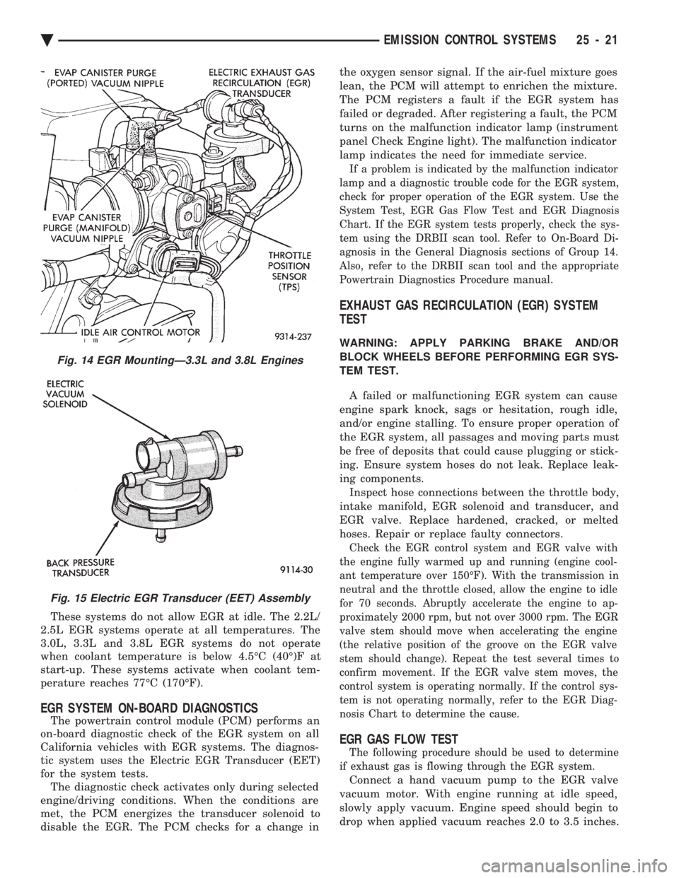
Fig. 14 EGR MountingÐ3.3L and 3.8L Engines
Fig. 15 Electric EGR Transducer (EET) Assembly
Ä EMISSION CONTROL SYSTEMS 25 - 21
Page 2413 of 2438

CHRYSLER
CORPORATION
SERVICE MANUAL and SUPPLEMENTS
1993 FRONT WHEEL DRIVE PASSENGER VEHICLES
To order the special service tools used and
illustrated, please refer to the instructions on
inside back cover.
NO PART OF THIS PUBLICATION MAY BE
REPRODUCED, STORED IN A RETRIEVAL
SYSTEM, OR TRANSMITTED, IN ANY FORM
OR BY ANY MEANS, ELECTRONIC, ME-
CHANICAL, PHOTOCOPYING, RECORDING,
OR OTHERWISE, WITHOUT THE PRIOR
WRITTEN PERMISSION OF CHRYSLER
CORPORATION.
Chrysler Corporation reserves the right to make changes in design or to make
additions to or improvements in its products without imposing any obligations
upon itself to install them on its products previously manufactured.
Litho in U.S.A. Copyright 1992 Chrysler Corporation 30M0792
NEXT PAGE ©