check oil CHEVROLET PLYMOUTH ACCLAIM 1993 Service Manual
[x] Cancel search | Manufacturer: CHEVROLET, Model Year: 1993, Model line: PLYMOUTH ACCLAIM, Model: CHEVROLET PLYMOUTH ACCLAIM 1993Pages: 2438, PDF Size: 74.98 MB
Page 2008 of 2438

GOVERNOR
To service the governor assembly in the vehicle, it
is not necessary to remove the transfer gear cover,
transfer gear, and governor support. The governor
may be serviced by removing the transaxle oil pan
and valve body assembly. With the oil pan and valve
body removed, the governor may be unbolted from
the governor support and removed. When cleaning or assembling the governor, make
sure the governor valves move freely in the bores of
the governor body.
ALUMINUM THREAD REPAIR
Damaged or worn threads in the aluminum tran-
saxle case and valve body can be repaired by the use
of Heli-Coils, or equivalent. This repair consists of
drilling out the worn-out damaged threads. Then tap-
ping the hole with a Heli-Coil tap, or equivalent, and
installing a Heli-Coil insert, or equivalent, into the
hole. This brings the hole back to its original thread
size. Heli-Coil, or equivalent, tools and inserts are
readily available from most automotive parts suppli-
ers.
OIL COOLERS AND TUBES REVERSE FLUSHING
When a transaxle failure has contaminated the
fluid, the oil cooler(s) must be flushed. The torque
converter must be replaced with an exchange unit.
This will insure that metal particles or sludged oil
are not transferred back into the reconditioned (or
replaced) transaxle.
CAUTION: If vehicle is equipped with two oil cool-
ers (one in the radiator tank, one in front of the ra-
diator) they must be flushed separately. Do not
attempt to flush both coolers at one time.
(1) Disconnect the cooler lines at the transmission.
(2) Using a hand suction gun filled with mineral
spirits, reverse flush the cooler. Force mineral spirits
into the From Cooler line of the cooler (Fig. 9) and
catch the exiting spirits from the To Coolerline.
Observe for the presence of debris in the exiting
fluid. Continue until fluid exiting is clear and free
from debris. (3) Using compressed air in intermittent spurts,
blow any remaining mineral spirits from the cooler,
again in the reverse direction. (4) To remove any remaining mineral spirits from
the cooler, one (1) quart of automatic transmission
fluid should be pumped through the cooler before re-
connecting. (5) If at any stage of the cleaning process, the
cooler does not freely pass fluid, the cooler must be
replaced.
OIL COOLER FLOW CHECK
After the new or repaired transmission has been
installed and filled to the proper level with auto-
matic transmission fluid. The flow should be checked
using the following procedure: (1) Disconnect the From coolerline at the trans-
mission and place a collecting container under the
disconnected line. (2) Run the engine at curb idle speed , with the
shift selector in neutral. (3) If the fluid flow is intermittent or it takes more
than 20 seconds to collect one quart of automatic
transmission fluid, the cooler should be replaced.
CAUTION: With the fluid set at the proper level,
fluid collection should not exceed (1) quart or inter-
nal damage to the transmission may occur.
(4) If flow is found to be within acceptable limits,
reconnect the cooler line. Then fill transmission to
the proper level, using the approved type of auto-
matic transmission fluid.
TRANSAXLE AND TORQUE CONVERTER REMOVAL
Transaxle removal does NOT require engine
removal. (1) The transaxle and torque converter must be re-
moved as an assembly; otherwise, the torque con-
verter drive plate, pump bushing, or oil seal may be
damaged. The drive plate will not support a load;
therefore, none of the weight of the transaxle should
be allowed to rest on the plate during removal. (2) Disconnect battery negative cable .
(3) Disconnect throttle linkage and shift linkage
from transaxle.
Fig. 9 Cooler Line Identification
21 - 48 TRANSAXLE Ä
Page 2022 of 2438

OIL PUMP-RECONDITION
Also, check gear side clearance with a straight
edge and a feeler gauge (See Specifications).
FRONT CLUTCH-RECONDITION
INSPECTION
Inspect plates and discs for flatness. They must not
be warped or cone shaped. Inspect facing material on all driving discs. Re-
place discs that are charred, glazed or heavily pitted.
Discs should also be replaced if they show evidence of
material flaking off or if facing material can be
scraped off easily. Inspect driving disc splines for
wear or other damage. Inspect steel plate surfaces for
burning, scoring, or damaged driving lugs. Replace if
necessary. Inspect steel plate lug grooves in clutch retainer
for smooth surfaces, plates must travel freely in
grooves. Inspect band contacting surface on clutch re-
tainer for scores, the contact surface should be pro-
tected from damage during disassembly and
handling. Note ball check in clutch retainer, make
sure ball moves freely. Inspect piston seal surfaces in
clutch retainer for nicks or deep scratches, light
scratches will not interfere with sealing of seals. In-
spect clutch retainer inner bore surface for wear from
reaction shaft support seal rings. Inspect clutch re-
tainer bushing for wear or scores. Inspect inside bore of piston for score marks, if
light, remove with crocus cloth. Inspect seal grooves
for nicks and burrs. Inspect seals for deterioration,
wear, and hardness. Inspect piston spring, retainer
and snap ring for distortion.
Fig. 4 Measuring Pump Clearance (Gear to Pocket)
Fig. 1 Reaction Shaft Support Bolts
Fig. 2 Reaction Shaft Support
Fig. 3 Inner and Outer Pump Gears
21 - 62 TRANSAXLE Ä
Page 2042 of 2438
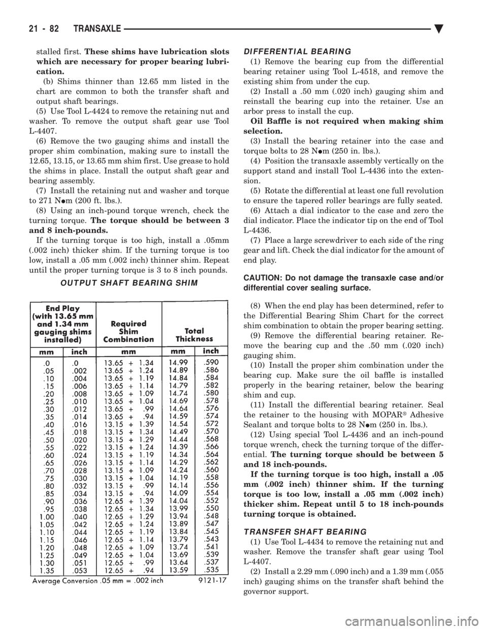
stalled first. These shims have lubrication slots
which are necessary for proper bearing lubri-
cation. (b) Shims thinner than 12.65 mm listed in the
chart are common to both the transfer shaft and
output shaft bearings.
(5) Use Tool L-4424 to remove the retaining nut and
washer. To remove the output shaft gear use Tool
L-4407. (6) Remove the two gauging shims and install the
proper shim combination, making sure to install the
12.65, 13.15, or 13.65 mm shim first. Use grease to hold
the shims in place. Install the output shaft gear and
bearing assembly. (7) Install the retaining nut and washer and torque
to 271 N Im (200 ft. lbs.).
(8) Using an inch-pound torque wrench, check the
turning torque. The torque should be between 3
and 8 inch-pounds. If the turning torque is too high, install a .05mm
(.002 inch) thicker shim. If the turning torque is too
low, install a .05 mm (.002 inch) thinner shim. Repeat
until the proper turning torque is 3 to 8 inch pounds.DIFFERENTIAL BEARING
(1) Remove the bearing cup from the differential
bearing retainer using Tool L-4518, and remove the
existing shim from under the cup. (2) Install a .50 mm (.020 inch) gauging shim and
reinstall the bearing cup into the retainer. Use an
arbor press to install the cup. Oil Baffle is not required when making shim
selection. (3) Install the bearing retainer into the case and
torque bolts to 28 N Im (250 in. lbs.).
(4) Position the transaxle assembly vertically on the
support stand and install Tool L-4436 into the exten-
sion. (5) Rotate the differential at least one full revolution
to ensure the tapered roller bearings are fully seated. (6) Attach a dial indicator to the case and zero the
dial indicator. Place the indicator tip on the end of Tool
L-4436. (7) Place a large screwdriver to each side of the ring
gear and lift. Check the dial indicator for the amount of
end play.
CAUTION: Do not damage the transaxle case and/or
differential cover sealing surface.
(8) When the end play has been determined, refer to
the Differential Bearing Shim Chart for the correct
shim combination to obtain the proper bearing setting. (9) Remove the differential bearing retainer. Re-
move the bearing cup and the .50 mm (.020 inch)
gauging shim. (10) Install the proper shim combination under the
bearing cup. Make sure the oil baffle is installed
properly in the bearing retainer, below the bearing
shim and cup. (11) Install the differential bearing retainer. Seal
the retainer to the housing with MOPAR tAdhesive
Sealant and torque bolts to 28 N Im (250 in. lbs.).
(12) Using special Tool L-4436 and an inch-pound
torque wrench, check the turning torque of the differ-
ential. The turning torque should be between 5
and 18 inch-pounds. If the turning torque is too high, install a .05
mm (.002 inch) thinner shim. If the turning
torque is too low, install a .05 mm (.002 inch)
thicker shim. Repeat until 5 to 18 inch-pounds
turning torque is obtained.
TRANSFER SHAFT BEARING
(1) Use Tool L-4434 to remove the retaining nut and
washer. Remove the transfer shaft gear using Tool
L-4407. (2) Install a 2.29 mm (.090 inch) and a 1.39 mm (.055
inch) gauging shims on the transfer shaft behind the
governor support.
OUTPUT SHAFT BEARING SHIM
21 - 82 TRANSAXLE Ä
Page 2045 of 2438
41TE FOUR SPEED AUTOMATIC TRANSAXLE INDEX
page page
41TE Transaxle General Diagnosis ........... 88
Aluminum Thread Repair ................... 98
Bearing Adjustment Procedure .............. 141
Clutch Air Pressure Tests .................. 95
Coolers and Tubes Reverse Flushing ......... 98
Diagnosis Chart ``B'' ....................... 90
Diagnosis Trouble Code Chart ``A'' ............ 89
Differential Repair ....................... 136
Fluid and Filter Changes ................... 93
Fluid Drain and Refill ..................... 93
Fluid Leakage-Torque Converter Housing Area . . 97
Fluid Level and Condition .................. 93
Gearshift Linkage Adjustment ............... 98
General Information ....................... 85
Hydraulic Pressure Tests ................... 94
Input Clutches-Recondition ................ 121
Oil Cooler Flow Check .................... 99 Oil Pump Seal Replace
................... 136
Park/Neutral Position Switch ............... 102
Pinion Factor Procedure .................. 104
Road Test .............................. 93
Selection of Lubricant ..................... 93
Solenoid Assembly-Replace ................ 101
Special Additives ......................... 93
Speed Sensor-Input ...................... 102
Speed Sensor-Output .................... 103
Torque Converter Clutch Break-In Procedure . . . 104
Transaxle Quick Learn Procedure ........... 103
Transaxle Recondition .................... 105
Transaxle Removal and Installation ........... 99
Transmission Control Module ............... 103
Transmission Range Switch ................ 102
Valve Body-Recondition ................... 132
GENERAL INFORMATION
The 41TE four-speed FWD transaxle uses fully-
adaptive controls. Adaptive controls are those which
perform their functions based on real-time feedback
sensor information. The transaxle uses hydraulically
applied clutches to shift a planetary gear train.
TRANSAXLE IDENTIFICATION
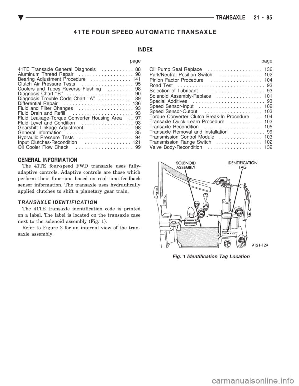
The 41TE transaxle identification code is printed
on a label. The label is located on the transaxle case
next to the solenoid assembly (Fig. 1). Refer to Figure 2 for an internal view of the tran-
saxle assembly.
Fig. 1 Identification Tag Location
Ä TRANSAXLE 21 - 85
Page 2053 of 2438
FLUID LEVEL AND CONDITION
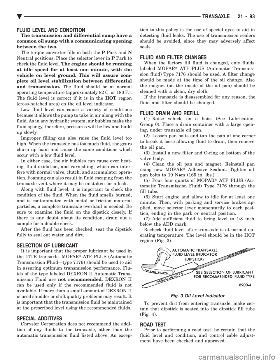
The transmission and differential sump have a
common oil sump with a communicating opening
between the two. The torque converter fills in both the PPark and N
Neutral positions. Place the selector lever in PPark to
check the fluid level. The engine should be running
at idle speed for at least one minute, with the
vehicle on level ground. This will assure com-
plete oil level stabilization between differential
and transmission. The fluid should be at normal
operating temperature (approximately 82 C. or 180 F.).
The fluid level is correct if it is in the HOTregion
(cross-hatched area) on the oil level indicator. Low fluid level can cause a variety of conditions
because it allows the pump to take in air along with the
fluid. As in any hydraulic system, air bubbles make the
fluid spongy, therefore, pressures will be low and build
up slowly. Improper filling can also raise the fluid level too
high. When the transaxle has too much fluid, the gears
churn up foam and cause the same conditions which
occur with a low fluid level. In either case, the air bubbles can cause over heat-
ing, fluid oxidation, and varnishing, which can inter-
fere with normal valve, clutch, and accumulator opera-
tion. Foaming can also result in fluid escaping from the
transaxle vent where it may be mistaken for a leak. Along with fluid level, it is important to check the
condition of the fluid. When the fluid smells burned,
and is contaminated with metal or friction material
particles, a complete transaxle overhaul is needed. Be
sure to examine the fluid on the dipstick closely. If
there is any doubt about its condition, drain out a
sample for a double check. After the fluid has been checked, seat the dipstick
fully to seal out water and dirt.
SELECTION OF LUBRICANT
It is important that the proper lubricant be used in
the 41TE transaxle. MOPAR tATF PLUS (Automatic
Transmission FluidÐtype 7176) should be used to aid
in assuring optimum transmission performance. Flu-
ids of the type labeled DEXRON II Automatic Trans-
mission Fluid are not recommended . DEXRON II
can be used only if the recommended fluid is not
available. If more than a small amount of DEXRON II
is used shudder or shift quality problems may result. It
is important that the transmission fluid be maintained
at the prescribed level using the recommended fluids.
SPECIAL ADDITIVES
Chrysler Corporation does not recommend the addi-
tion of any fluids to the transaxle, other than the
automatic transmission fluid listed above. An excep- tion to this policy is the use of special dyes to aid in
detecting fluid leaks. The use of transmission sealers
should be avoided, since they may adversely affect
seals.
FLUID AND FILTER CHANGES
When the factory fill fluid is changed, only fluids
labeled MOPAR tATF PLUS (Automatic Transmis-
sion fluid) Type 7176 should be used. A filter change
should be made at the time of the oil change. Also
the magnet (on the inside of the oil pan) should be
cleaned with a clean, dry cloth. If the transaxle is disassembled for any reason, the
fluid and filter should be changed.
FLUID DRAIN AND REFILL
(1) Raise vehicle on a hoist (See Lubrication,
Group 0). Place a drain container with a large open-
ing, under transaxle oil pan. (2) Loosen pan bolts and tap the pan at one corner
to break it loose allowing fluid to drain, then remove
the oil pan. (3) Install a new filter and O-ring on bottom of the
valve body. (4) Clean the oil pan and magnet. Reinstall pan
using new MOPAR tAdhesive Sealant. Tighten oil
pan bolts to 19 N Im (165 in. lbs.).
(5) Pour four quarts of MOPAR tATF PLUS (Au-
tomatic Transmission Fluid) Type 7176 through the
fill tube. (6) Start engine and allow to idle for at least one
minute. Then, with parking and service brakes ap-
plied, move selector lever momentarily to each posi-
tion, ending in the park or neutral position. (7) Add sufficient fluid to bring level to 1/8 inch
below the ADD mark. Recheck fluid level after transaxle is at normal op-
erating temperature. The level should be in the HOT
region (Fig. 3).
To prevent dirt from entering transaxle, make cer-
tain that dipstick is seated into the dipstick fill tube
(Fig. 4).
ROAD TEST
Prior to performing a road test, be certain that the
fluid level and condition, and control cable adjust-
ment have been checked and approved.
Fig. 3 Oil Level Indicator
Ä TRANSAXLE 21 - 93
Page 2054 of 2438
During the road test, the transaxle should be oper-
ated in each position to check for slipping and any
variation in shifting. If vehicle operates properly at highway speeds, but
has poor acceleration, the torque converter stator
overrunning clutch may be slipping. If through-gear
acceleration is normal, but high throttle opening is
required to maintain highway speeds, the torque con-
verter stator clutch may have seized. Both of these
stator defects require replacement of the torque con-
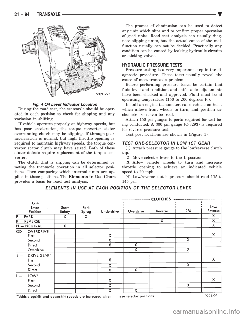
verter. The clutch that is slipping can be determined by
noting the transaxle operation in all selector posi-
tions. Then comparing which internal units are ap-
plied in those positions. The Elements in Use Chart
provides a basis for road test analysis. The process of elimination can be used to detect
any unit which slips and to confirm proper operation
of good units. Road test analysis can usually diag-
nose slipping units, but the actual cause of the mal-
function usually can not be decided. Practically any
condition can be caused by leaking hydraulic circuits
or sticking valves.
HYDRAULIC PRESSURE TESTS
Pressure testing is a very important step in the di-
agnostic procedure. These tests usually reveal the
cause of most transaxle problems. Before performing pressure tests, be certain that
fluid level and condition, and shift cable adjustments
have been checked and approved. Fluid must be at
operating temperature (150 to 200 degrees F.). Install an engine tachometer, raise vehicle on hoist
which allows front wheels to turn, and position ta-
chometer so it can be read. Attach 150 psi gauges to ports required for test be-
ing conducted. A 300 psi gauge (C-3293) is required
for reverse pressure test. Test port locations are shown in (Figure 1).
TEST ONE-SELECTOR IN LOW 1ST GEAR
(1) Attach pressure gauge to the low/reverse clutch
tap. (2) Move selector lever to the L position.
(3) Allow vehicle wheels to turn and increase
throttle opening to achieve an indicated vehicle
speed to 20 mph. (4) Low/reverse clutch pressure should read 115 to
145 psi.
ELEMENTS IN USE AT EACH POSITION OF THE SELECTOR LEVER
Fig. 4 Oil Level Indicator Location
21 - 94 TRANSAXLE Ä
Page 2055 of 2438
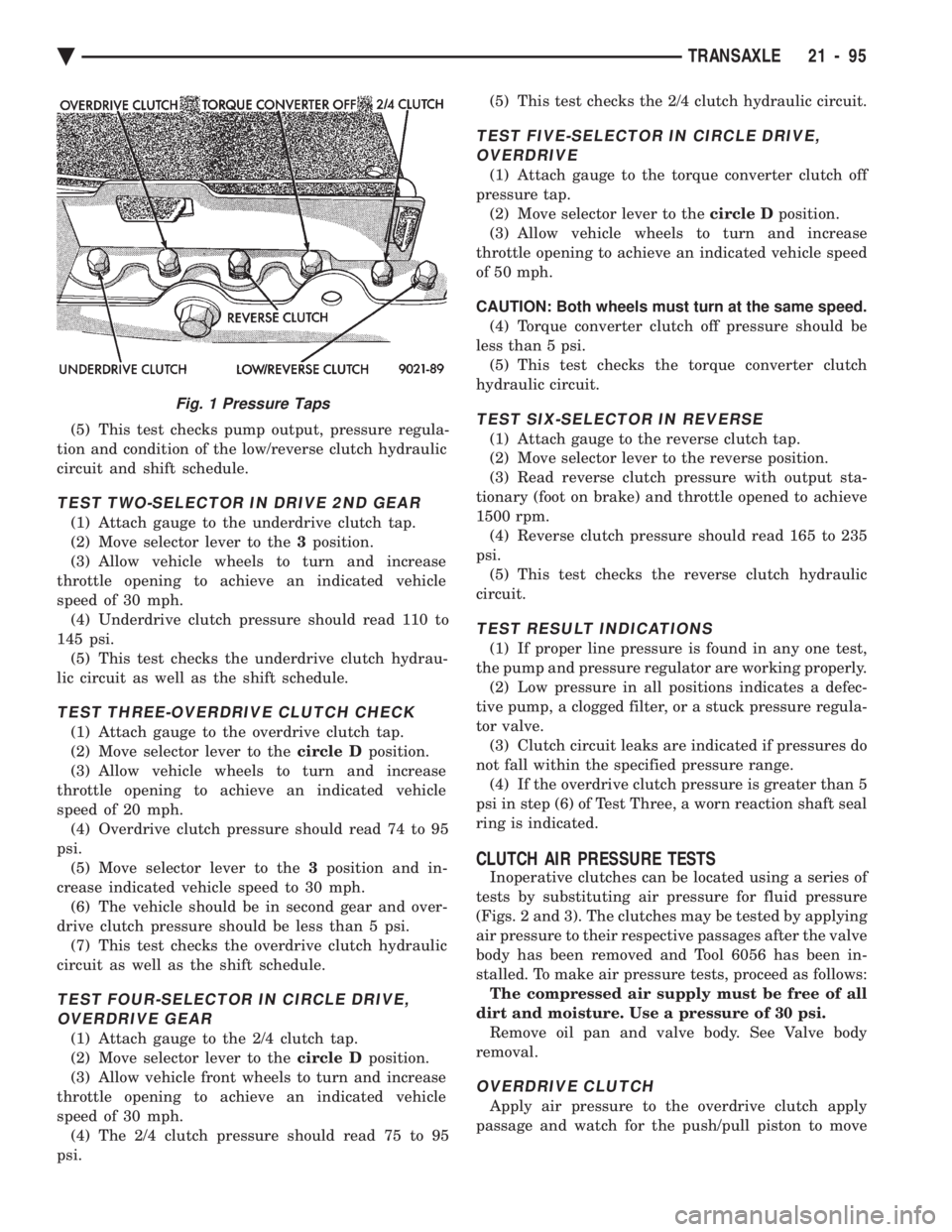
(5) This test checks pump output, pressure regula-
tion and condition of the low/reverse clutch hydraulic
circuit and shift schedule.
TEST TWO-SELECTOR IN DRIVE 2ND GEAR
(1) Attach gauge to the underdrive clutch tap.
(2) Move selector lever to the 3position.
(3) Allow vehicle wheels to turn and increase
throttle opening to achieve an indicated vehicle
speed of 30 mph. (4) Underdrive clutch pressure should read 110 to
145 psi. (5) This test checks the underdrive clutch hydrau-
lic circuit as well as the shift schedule.
TEST THREE-OVERDRIVE CLUTCH CHECK
(1) Attach gauge to the overdrive clutch tap.
(2) Move selector lever to the circle Dposition.
(3) Allow vehicle wheels to turn and increase
throttle opening to achieve an indicated vehicle
speed of 20 mph. (4) Overdrive clutch pressure should read 74 to 95
psi. (5) Move selector lever to the 3position and in-
crease indicated vehicle speed to 30 mph. (6) The vehicle should be in second gear and over-
drive clutch pressure should be less than 5 psi. (7) This test checks the overdrive clutch hydraulic
circuit as well as the shift schedule.
TEST FOUR-SELECTOR IN CIRCLE DRIVE, OVERDRIVE GEAR
(1) Attach gauge to the 2/4 clutch tap.
(2) Move selector lever to the circle Dposition.
(3) Allow vehicle front wheels to turn and increase
throttle opening to achieve an indicated vehicle
speed of 30 mph. (4) The 2/4 clutch pressure should read 75 to 95
psi. (5) This test checks the 2/4 clutch hydraulic circuit.
TEST FIVE-SELECTOR IN CIRCLE DRIVE,
OVERDRIVE
(1) Attach gauge to the torque converter clutch off
pressure tap. (2) Move selector lever to the circle Dposition.
(3) Allow vehicle wheels to turn and increase
throttle opening to achieve an indicated vehicle speed
of 50 mph.
CAUTION: Both wheels must turn at the same speed. (4) Torque converter clutch off pressure should be
less than 5 psi. (5) This test checks the torque converter clutch
hydraulic circuit.
TEST SIX-SELECTOR IN REVERSE
(1) Attach gauge to the reverse clutch tap.
(2) Move selector lever to the reverse position.
(3) Read reverse clutch pressure with output sta-
tionary (foot on brake) and throttle opened to achieve
1500 rpm. (4) Reverse clutch pressure should read 165 to 235
psi. (5) This test checks the reverse clutch hydraulic
circuit.
TEST RESULT INDICATIONS
(1) If proper line pressure is found in any one test,
the pump and pressure regulator are working properly. (2) Low pressure in all positions indicates a defec-
tive pump, a clogged filter, or a stuck pressure regula-
tor valve. (3) Clutch circuit leaks are indicated if pressures do
not fall within the specified pressure range. (4) If the overdrive clutch pressure is greater than 5
psi in step (6) of Test Three, a worn reaction shaft seal
ring is indicated.
CLUTCH AIR PRESSURE TESTS
Inoperative clutches can be located using a series of
tests by substituting air pressure for fluid pressure
(Figs. 2 and 3). The clutches may be tested by applying
air pressure to their respective passages after the valve
body has been removed and Tool 6056 has been in-
stalled. To make air pressure tests, proceed as follows: The compressed air supply must be free of all
dirt and moisture. Use a pressure of 30 psi. Remove oil pan and valve body. See Valve body
removal.
OVERDRIVE CLUTCH
Apply air pressure to the overdrive clutch apply
passage and watch for the push/pull piston to move
Fig. 1 Pressure Taps
Ä TRANSAXLE 21 - 95
Page 2057 of 2438
first separator plate and watch carefully for the pis-
ton to move forward. The piston should return to its
original position after the air pressure is removed.
UNDERDRIVE CLUTCH
Because this clutch piston cannot be seen, its oper-
ation is checked by function. Air pressure is applied
to the low/reverse and the 2/4 clutches. This locks
the output shaft. Use a piece of rubber hose wrapped
around the input shaft and a pair of clamp-on pliers
to turn the input shaft. Next apply air pressure to
the underdrive clutch. The input shaft should not ro-
tate with hand torque. Release the air pressure and
confirm that the input shaft will rotate.
FLUID LEAKAGE-TORQUE CONVERTER HOUSING
AREA
(1) Check for source of leakage.
Since fluid leakage at or around the torque con-
verter area may originate from an engine oil leak,
the area should be examined closely. Factory fill
fluid is dyed red and, therefore, can be distinguished
from engine oil. (2) Prior to removing the transaxle, perform the
following checks: When leakage is determined to originate from the
transaxle, check fluid level prior to removal of the
transaxle and torque converter. High oil level can result in oil leakage out the vent
in the manual shaft. If the fluid level is high, adjust
to proper level. After performing this operation, inspect for leak-
age. If a leak persists, perform the following opera-
tion on the vehicle to determine if it is the torque
converter or transaxle that is leaking.
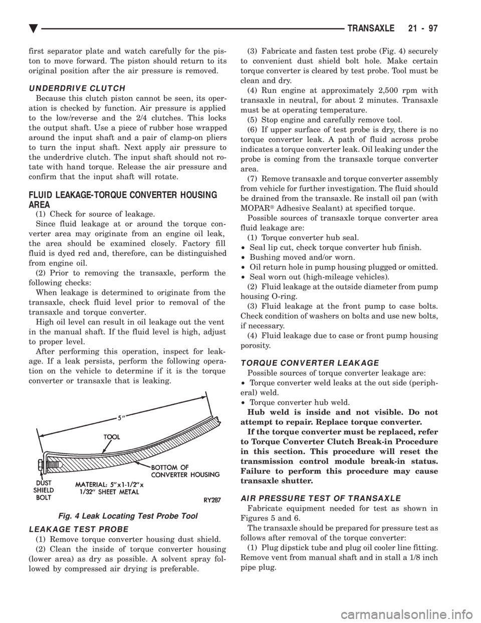
LEAKAGE TEST PROBE
(1) Remove torque converter housing dust shield.
(2) Clean the inside of torque converter housing
(lower area) as dry as possible. A solvent spray fol-
lowed by compressed air drying is preferable. (3) Fabricate and fasten test probe (Fig. 4) securely
to convenient dust shield bolt hole. Make certain
torque converter is cleared by test probe. Tool must be
clean and dry. (4) Run engine at approximately 2,500 rpm with
transaxle in neutral, for about 2 minutes. Transaxle
must be at operating temperature. (5) Stop engine and carefully remove tool.
(6) If upper surface of test probe is dry, there is no
torque converter leak. A path of fluid across probe
indicates a torque converter leak. Oil leaking under the
probe is coming from the transaxle torque converter
area. (7) Remove transaxle and torque converter assembly
from vehicle for further investigation. The fluid should
be drained from the transaxle. Re install oil pan (with
MOPAR tAdhesive Sealant) at specified torque.
Possible sources of transaxle torque converter area
fluid leakage are: (1) Torque converter hub seal.
² Seal lip cut, check torque converter hub finish.
² Bushing moved and/or worn.
² Oil return hole in pump housing plugged or omitted.
² Seal worn out (high-mileage vehicles).
(2) Fluid leakage at the outside diameter from pump
housing O-ring. (3) Fluid leakage at the front pump to case bolts.
Check condition of washers on bolts and use new bolts,
if necessary. (4) Fluid leakage due to case or front pump housing
porosity.
TORQUE CONVERTER LEAKAGE
Possible sources of torque converter leakage are:
² Torque converter weld leaks at the out side (periph-
eral) weld.
² Torque converter hub weld.
Hub weld is inside and not visible. Do not
attempt to repair. Replace torque converter. If the torque converter must be replaced, refer
to Torque Converter Clutch Break-in Procedure
in this section. This procedure will reset the
transmission control module break-in status.
Failure to perform this procedure may cause
transaxle shutter.
AIR PRESSURE TEST OF TRANSAXLE
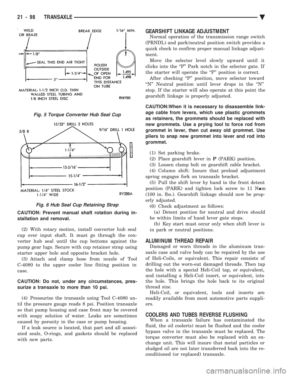
Fabricate equipment needed for test as shown in
Figures 5 and 6. The transaxle should be prepared for pressure test as
follows after removal of the torque converter: (1) Plug dipstick tube and plug oil cooler line fitting.
Remove vent from manual shaft and in stall a 1/8 inch
pipe plug.Fig. 4 Leak Locating Test Probe Tool
Ä TRANSAXLE 21 - 97
Page 2058 of 2438
CAUTION: Prevent manual shaft rotation during in-
stallation and removal. (2) With rotary motion, install converter hub seal
cup over input shaft. It must go through the con-
verter hub seal until the cup bottoms against the
pump gear lugs. Secure with cup retainer strap using
starter upper hole and opposite bracket hole. (3) Attach and clamp hose from nozzle of Tool
C-4080 to the upper cooler line fitting position in
case.
CAUTION: Do not, under any circumstances, pres-
surize a transaxle to more than 10 psi.
(4) Pressurize the transaxle using Tool C-4080 un-
til the pressure gauge reads 8 psi. Position transaxle
so that pump housing and case front may be covered
with soapy solution of water. Leaks are sometimes
caused by porosity in the case or pump housing. If a leak source is located, that part and all associ-
ated seals, O-rings, and gaskets should be replaced
with new parts.
GEARSHIFT LINKAGE ADJUSTMENT
Normal operation of the transmission range switch
(PRNDL) and park/neutral position switch provides a
quick check to confirm proper manual linkage adjust-
ment. Move the selector level slowly upward until it
clicks into the ``P'' Park notch in the selector gate. If
the starter will operate the ``P'' position is correct. After checking ``P'' position, move selector toward
``N'' Neutral position until lever drops in the ``N''
stop. If the starter will also operate at this point the
gearshift linkage is properly adjusted.
CAUTION:When it is necessary to disassemble link-
age cable from levers, which use plastic grommets
as retainers, the grommets should be replaced with
new grommets. Use a prying tool to force rod from
grommet in lever, then cut away old grommet. Use
pliers to snap new grommet into lever and rod into
grommet.
(1) Set parking brake.
(2) Place gearshift lever in P(PARK) position.
(3) Loosen clamp bolt on gearshift cable bracket.
(4) Column shift: Insure that preload adjustment
spring engages fork on transaxle bracket. (5) Pull the shift lever by hand to the front detent
position (PARK) and tighten lock screw to 11 N Im
(100 in. lbs.). Gearshift linkage should now be prop-
erly adjusted. (6) Check adjustment as follows:(a) Detent position for neutral and drive should
be within limits of hand lever gate stops. (b) Key start must occur only when shift lever is
in park or neutral positions.
ALUMINUM THREAD REPAIR
Damaged or worn threads in the aluminum tran-
saxle case and valve body can be repaired by the use
of Heli-Coils, or equivalent. This repair consists of
drilling out the worn-out damaged threads. Then tap
the hole with a special Heli-Coil tap, or equivalent,
and installing a Heli-Coil insert, or equivalent, into
the hole. This brings the hole back to its original
thread size. Heli-Coil, or equivalent, tools and inserts are
readily available from most automotive parts suppli-
ers.
COOLERS AND TUBES REVERSE FLUSHING
When a transaxle failure has contaminated the
fluid, the oil cooler(s) must be flushed and the cooler
bypass valve in the transaxle must be replaced. The
torque converter must also be replaced with an ex-
change unit. This will insure that metal particles or
sludged oil are not later transferred back into the re-
conditioned (or replaced) transaxle.
Fig. 5 Torque Converter Hub Seal Cup
Fig. 6 Hub Seal Cup Retaining Strap
21 - 98 TRANSAXLE Ä
Page 2059 of 2438
CAUTION: If the vehicle is equipped with two oil
coolers (one in the radiator tank, one in front of the
radiator) they must be flushed separately. Do not
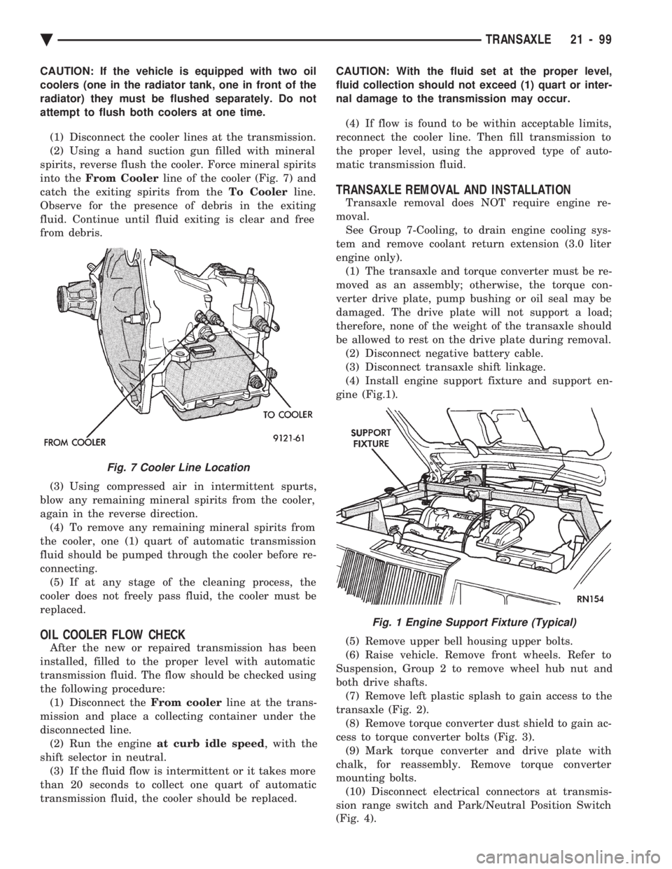
attempt to flush both coolers at one time. (1) Disconnect the cooler lines at the transmission.
(2) Using a hand suction gun filled with mineral
spirits, reverse flush the cooler. Force mineral spirits
into the From Cooler line of the cooler (Fig. 7) and
catch the exiting spirits from the To Coolerline.
Observe for the presence of debris in the exiting
fluid. Continue until fluid exiting is clear and free
from debris.
(3) Using compressed air in intermittent spurts,
blow any remaining mineral spirits from the cooler,
again in the reverse direction. (4) To remove any remaining mineral spirits from
the cooler, one (1) quart of automatic transmission
fluid should be pumped through the cooler before re-
connecting. (5) If at any stage of the cleaning process, the
cooler does not freely pass fluid, the cooler must be
replaced.
OIL COOLER FLOW CHECK
After the new or repaired transmission has been
installed, filled to the proper level with automatic
transmission fluid. The flow should be checked using
the following procedure: (1) Disconnect the From coolerline at the trans-
mission and place a collecting container under the
disconnected line. (2) Run the engine at curb idle speed , with the
shift selector in neutral. (3) If the fluid flow is intermittent or it takes more
than 20 seconds to collect one quart of automatic
transmission fluid, the cooler should be replaced. CAUTION: With the fluid set at the proper level,
fluid collection should not exceed (1) quart or inter-
nal damage to the transmission may occur.
(4) If flow is found to be within acceptable limits,
reconnect the cooler line. Then fill transmission to
the proper level, using the approved type of auto-
matic transmission fluid.
TRANSAXLE REMOVAL AND INSTALLATION
Transaxle removal does NOT require engine re-
moval. See Group 7-Cooling, to drain engine cooling sys-
tem and remove coolant return extension (3.0 liter
engine only). (1) The transaxle and torque converter must be re-
moved as an assembly; otherwise, the torque con-
verter drive plate, pump bushing or oil seal may be
damaged. The drive plate will not support a load;
therefore, none of the weight of the transaxle should
be allowed to rest on the drive plate during removal. (2) Disconnect negative battery cable.
(3) Disconnect transaxle shift linkage.
(4) Install engine support fixture and support en-
gine (Fig.1).
(5) Remove upper bell housing upper bolts.
(6) Raise vehicle. Remove front wheels. Refer to
Suspension, Group 2 to remove wheel hub nut and
both drive shafts. (7) Remove left plastic splash to gain access to the
transaxle (Fig. 2). (8) Remove torque converter dust shield to gain ac-
cess to torque converter bolts (Fig. 3). (9) Mark torque converter and drive plate with
chalk, for reassembly. Remove torque converter
mounting bolts. (10) Disconnect electrical connectors at transmis-
sion range switch and Park/Neutral Position Switch
(Fig. 4).
Fig. 7 Cooler Line Location
Fig. 1 Engine Support Fixture (Typical)
Ä TRANSAXLE 21 - 99