CHEVROLET PLYMOUTH ACCLAIM 1993 Service Manual
Manufacturer: CHEVROLET, Model Year: 1993, Model line: PLYMOUTH ACCLAIM, Model: CHEVROLET PLYMOUTH ACCLAIM 1993Pages: 2438, PDF Size: 74.98 MB
Page 2251 of 2438
HYDRAULIC SYSTEMS
The power convertible top hydraulic system con-
sists of;
² Two hydraulic cylinders
² Hydraulic lines
² Electric hydraulic pump and reservoir
² Dual relays
HYDRAULIC SYSTEM TESTS
The convertible top will raise slowly or make ab-
normal noise if the hydraulic fluid level is low. (1) Remove sling well and floor cover.
(2) With the top up and latched, remove the reser-
voir fill plug. (3) Visually inspect fluid level. If low, inspect for
leak in hydraulic system. (4) Repair or replace components, as necessary.
(5) Fill reservoir with Dexron tII, Type A, auto-
matic transmission fluid to the bottom of the fill
hole. (6) Replace fill plug and lower top.
(7) Raise top and verify fluid level.
(8) Install sling well and floor cover.
HYDRAULIC PUMP ASSEMBLY
HYDRAULIC PUMP REMOVAL (FIG. 13)
(1) Disconnect battery negative cable.
(2) Remove sling well and floor cover from behind
rear seat. (3) Disconnect pump wire connector and ground
connection. (4) Disconnect hydraulic lines from pump.
(5) Remove motor pump assembly from vehicle.
The rubber mounts are pressed and locked into the
mounting bracket. Pull up motor assembly to re-
move.
HYDRAULIC PUMP INSTALLATION
Reverse the preceding operation
HYDRAULIC CYLINDER
HYDRAULIC CYLINDER REMOVAL
(1) Disconnect battery negative cable.
(2) Remove interior trim as necessary to gain ac-
cess to hydraulic cylinders. (3) Remove cylinder mounting bracket and nut.
(4) Remove pivot bolt holding cylinder shaft to top
linkage. (5) Disconnect hydraulic lines from the cylinder.
(6) Remove cylinder from vehicle.
HYDRAULIC CYLINDER INSTALLATION
Reverse the preceding operation, and verify each
hydraulic seal is in place when connecting the line to
the cylinder. Replace seal if damaged.
HYDRAULIC PUMP LINE SEALS
HYDRAULIC PUMP LINE SEALS REMOVAL
(1) Disconnect battery negative cable.
(2) Disconnect hydraulic lines from pump and re-
move seals.
HYDRAULIC PUMP LINE SEALS INSTALLATION
Reverse the preceding operation.
HYDRAULIC CYLINDER LINE SEALS
REMOVAL
(1) Remove hydraulic cylinder to gain access to hy-
draulic line connections. (2) Disconnect hydraulic lines from cylinder and
remove seals.
INSTALLATION
Reverse the preceding operation.
Ä AJ/27-BODY 23 - 95
Page 2252 of 2438
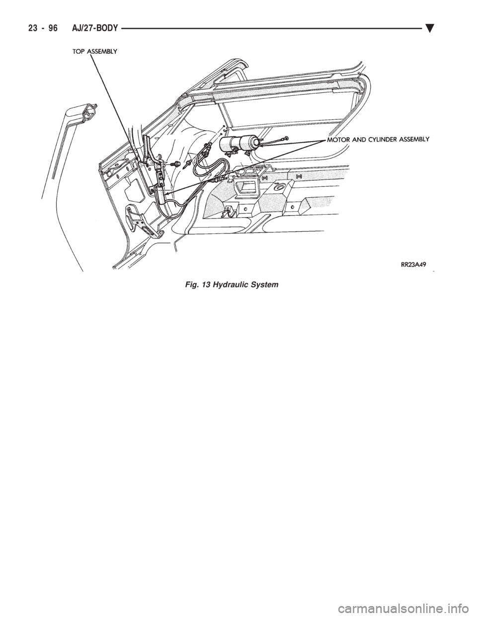
Fig. 13 Hydraulic System
23 - 96 AJ/27-BODY Ä
Page 2253 of 2438
AP-VEHICLE BODY COMPONENT SERVICE INDEX
page page
A-Pillar and Roof Rail Mouldings ............ 109
B-Pillar Trim PanelÐAP-44 Body ............ 109
Body Side Moulding and Applique ........... 108
Cowl Panel Trim and Scuff Plates ........... 109
Door Opening Weatherstrips ............... 107
Floor Carpet ........................... 113
Front Center Console .................... 113
Front Door and Hinge .................... 100
Front Door Belt Moulding and Weatherstrip .... 102
Front Door Glass ........................ 101
Front Door Glass Channel and Run Weatherstrip .......................... 103
Front Door Glass Run Lower Channels ....... 103
Front Door Latch ........................ 101
Front Door Side View Mirror ............... 101
Front Door Trim PanelÐAP-24/44 Body ....... 99
Front Door Water Shield .................. 100
Front Door Window Regulator/Manual ........ 103
Front Door Window Regulator/Power ......... 104
Front End Splash Shields .................. 99
Front Power Door Lock Actuator ............ 102
Front Seat BeltsÐAP-24 Body .............. 110
Front Seat BeltsÐAP-44 Body .............. 110
Front Seats ............................ 111
Grille .................................. 97
Grille Opening Panel ...................... 97
Head Lining ............................ 114
Hood and Hinges ........................ 97 Hood Latch and Release Cable
.............. 98
Lift Gate Luggage Rack ................... 116
Lift Gate Remote Release Cable ............ 115
Lower Quarter Trim PanelÐAP-44 Body ...... 109
Outside Front Door Latch Release Handle ..... 101
Outside Rear Door Latch Release Handle ..... 105
Overhead Console ....................... 113
Quarter Glass Weatherstrip ................ 108
Quarter Glass Window ................... 108
Quarter Trim PanelÐAP-44 Body ........... 109
Rear Door and Hinge .................... 104
Rear Door Belt Moulding and Weatherstrip .... 106
Rear Door Glass ........................ 106
Rear Door Glass Run Weatherstrip .......... 107
Rear Door Latch ........................ 105
Rear Door Silencer and Water Shield ........ 104
Rear Door Stationary Glass ................ 107
Rear Door Trim Panel .................... 104
Rear Door Window Regulator/Manual ........ 107
Rear Door Window Regulator/Power ......... 107
Rear Power Door Lock Actuator ............ 106
Rear Seat Belts ......................... 111
Rear Seats ............................ 112
Rear Window Glass ...................... 115
Sun Roof Air Deflector ................... 114
Sun Roof Drain Tubes .................... 115
Sun Roof Weatherstrip ................... 114
Upper Quarter Trim PanelÐAP-44 Body ...... 109
GRILLE
REMOVAL (FIG. 1)
(1) Raise hood to the up position.
(2) Remove screws holding grille to grille opening
panel. (3) Separate grille from vehicle.
INSTALLATION
Reverse the preceding operation.
GRILLE OPENING PANEL
REMOVAL (FIG. 1)
(1) Remove grille from grille opening panel.
(2) Remove headlamp assemblies. Refer to Group
8L. Lamps for proper procedures. (3) Remove bolts holding grille opening panel to
closure panel brackets. (4) Remove bolt holding grille opening panel to
brace in front of radiator. (5) Separate grille opening panel from vehicle.
INSTALLATION
Reverse the preceding operation.
HOOD AND HINGES
HOOD REMOVAL (FIG. 2)
(1) Raise hood to full up position.
(2) Disconnect the under hood lamp wire connec-
tor. (3) Mark all bolt and hinge attachment locations
with a grease pencil or other suitable device to pro-
vide reference marks for installation. When install-
Fig. 1 Grille and Grille Opening Panel
Ä AP-BODY 23 - 97
Page 2254 of 2438
ing hood, align all marks and secure bolts. The hood
should be aligned to 4 mm (0.160 in.) gap to the front
fenders and flush across the top surfaces along fend-
ers.(4) Remove the top hood to hinge attaching bolts
and loosen the bottom bolts until they can be re-
moved by hand. (5) With assistance of a helper at the opposite side
of the vehicle to support the hood, remove the bottom
hood to hinge attaching bolts. Separate the hood
from the vehicle.
HOOD INSTALLATION
Reverse the preceding operation.
HOOD HINGE REMOVAL (FIG. 3)
(1) Support hood on the side that requires hinge
replacement. (2) Mark all bolt and hinge attachment locations
with a grease pencil or other suitable device to pro-
vide reference marks for installation. When install-
ing hood hinge, align all marks and secure bolts. The
hood should be aligned to 4 mm (0.160 in.) gap to the
front fenders and flush across the top surfaces along
fenders. Shims can be added or removed under hood
hinge to achieve proper hood height. (3) Remove hood to hinge attaching bolts.
(4) Remove hood hinge to front fender attaching
bolts and separate hinge from vehicle.
HOOD HINGE INSTALLATION
Reverse the preceding operation. If necessary, paint
new hinge before installation.
HOOD LATCH AND RELEASE CABLE
HOOD LATCH REMOVAL (FIG. 4)
(1) Raise hood top the full up position.
(2) Remove hood latch attaching bolts holding
latch to radiator closure panel and separate from ve-
hicle. (3) Pry release cable casing attachment from slot
receiver on latch, disengage cable end from latch arm
hook.
HOOD LATCH INSTALLATION
Reverse the preceding operation.
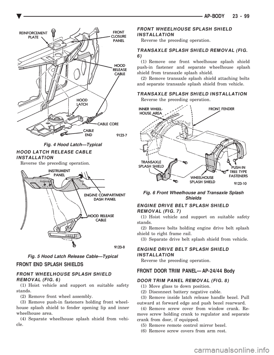
HOOD LATCH RELEASE CABLE REMOVAL (FIG. 5)
(1) Raise hood to the full up position.
(2) Remove push-in fasteners holding hood latch
cover to radiator closure panel and separate cover
from vehicle. (3) Disconnect hood release cable casing and cable
end from hood latch assembly. Refer to Hood Latch
Removal procedure in this section. (4) Remove hood latch release cable handle attach-
ing bolts from under left lower edge of instrument
panel. (5) Disengage release cable rubber grommet from
engine compartment dash panel behind instrument
panel. (6) Rout cable assembly through engine compart-
ment around battery, under fender lip, under relay
bank, and under wiring harnesses, toward dash
panel. Push cable through access hole in dash panel
under the brake master cylinder, into passenger com-
partment.
Fig. 2 Hood AssemblyÐTypical
Fig. 3 Hood Hinge Assembly
23 - 98 AP-BODY Ä
Page 2255 of 2438
HOOD LATCH RELEASE CABLE INSTALLATION
Reverse the preceding operation.
FRONT END SPLASH SHIELDS
FRONT WHEELHOUSE SPLASH SHIELDREMOVAL (FIG. 6)
(1) Hoist vehicle and support on suitable safety
stands. (2) Remove front wheel assembly.
(3) Remove push-in fasteners holding front wheel-
house splash shield to fender opening lip and inner
wheelhouse area. (4) Separate wheelhouse splash shield from vehi-
cle.
FRONT WHEELHOUSE SPLASH SHIELD INSTALLATION
Reverse the preceding operation.
TRANSAXLE SPLASH SHIELD REMOVAL (FIG.6)
(1) Remove one front wheelhouse splash shield
push-in fastener and separate wheelhouse splash
shield from transaxle splash shield. (2) Remove transaxle splash shield attaching bolts
and separate transaxle splash shield from vehicle.
TRANSAXLE SPLASH SHIELD INSTALLATION
Reverse the preceding operation.
ENGINE DRIVE BELT SPLASH SHIELD REMOVAL (FIG. 7)
(1) Hoist vehicle and support on suitable safety
stands. (2) Remove bolts holding engine drive belt splash
shield to right frame rail. (3) Separate drive belt splash shield from vehicle.
ENGINE DRIVE BELT SPLASH SHIELDINSTALLATION
Reverse the preceding operation.
FRONT DOOR TRIM PANELÐAP-24/44 Body
DOOR TRIM PANEL REMOVAL (FIG. 8)
(1) Move glass to down position.
(2) Disconnect battery negative cable.
(3) Remove inside latch release handle bezel. Pull
outward at forward edge and push bezel rearward. (4) Remove screw cover from window crank. Re-
move screw holding crank to regulator and separate
crank from door, if equipped. (5) Remove remote control mirror bezel.
(6) Remove screw covers from arm rest.
Fig. 4 Hood LatchÐTypical
Fig. 5 Hood Latch Release CableÐTypical
Fig. 6 Front Wheelhouse and Transaxle Splash Shields
Ä AP-BODY 23 - 99
Page 2256 of 2438
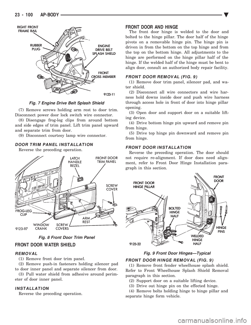
(7) Remove screws holding arm rest to door trim.
Disconnect power door lock switch wire connector. (8) Disengage frog-leg clips from around bottom
and side edges of trim panel. Lift trim panel upward
and separate trim from door. (9) Disconnect courtesy lamp wire connector.
DOOR TRIM PANEL INSTALLATION
Reverse the preceding operation.
FRONT DOOR WATER SHIELD
REMOVAL
(1) Remove front door trim panel.
(2) Remove push-in fasteners holding silencer pad
to door inner panel and separate silencer from door. (3) Pull water shield from adhesive around perim-
eter of door inner panel.
INSTALLATION
Reverse the preceding operation.
FRONT DOOR AND HINGE
The front door hinge is welded to the door and
bolted to the hinge pillar. The door half of the hinge
pivots on a removable hinge pin. The hinge pin is
driven in from the bottom on the top hinge and from
the top on the bottom hinge. All adjustments to the
hinge are performed on the hinge pillar half of the
hinge. If the welded half of the hinge must be bent to
align door, consult an authorized body repair facility.
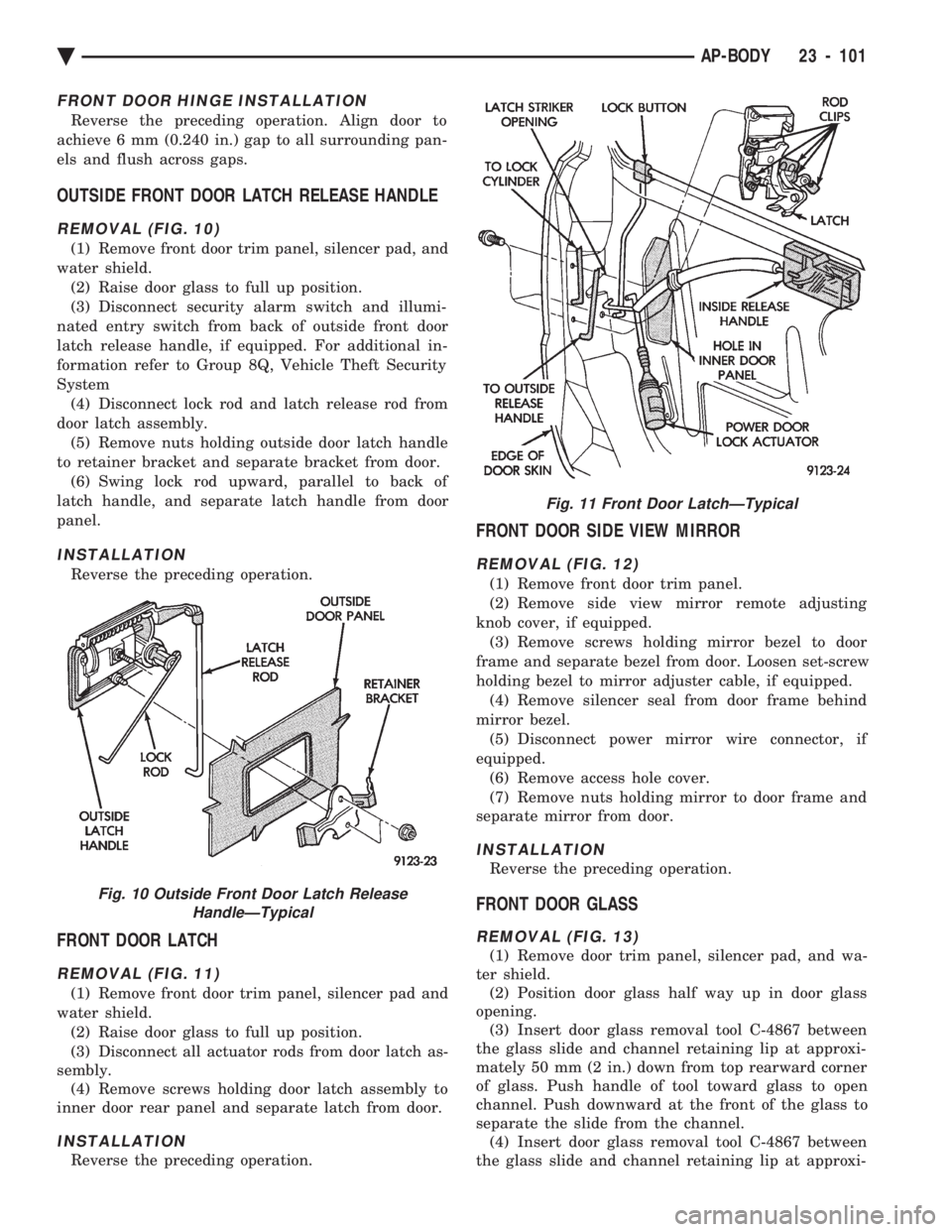
FRONT DOOR REMOVAL (FIG. 9)
(1) Remove door trim panel, silencer pad, and wa-
ter shield. (2) Disconnect all wire connectors and wire har-
ness hold downs inside door and push wire harness
through access hole in front of door into hinge pillar
opening. (3) Open door and support door on a suitable lift-
ing device. (4) Drive bottom hinge pin upward and remove pin
from hinge. (5) Drive top hinge pin downward and remove pin
from hinge.
FRONT DOOR INSTALLATION
Reverse the preceding operation. The door should
not require re-alignment. If door does need align-
ment, refer to Front Door Hinge Installation para-
graph in this section.
FRONT DOOR HINGE REMOVAL (FIG. 9)
(1) Remove front fender wheelhouse splash shield.
Refer to Front Wheelhouse Splash Shield Removal
paragraph in this section. (2) Support door on a suitable lifting device.
(3) Drive out hinge pin on the effected hinge.
(4) Remove bolts holding hinge to hinge pillar and
separate hinge form vehicle.
Fig. 7 Engine Drive Belt Splash Shield
Fig. 8 Front Door Trim Panel
Fig. 9 Front Door HingesÐTypical
23 - 100 AP-BODY Ä
Page 2257 of 2438
FRONT DOOR HINGE INSTALLATION
Reverse the preceding operation. Align door to
achieve 6 mm (0.240 in.) gap to all surrounding pan-
els and flush across gaps.
OUTSIDE FRONT DOOR LATCH RELEASE HANDLE
REMOVAL (FIG. 10)
(1) Remove front door trim panel, silencer pad, and
water shield. (2) Raise door glass to full up position.
(3) Disconnect security alarm switch and illumi-
nated entry switch from back of outside front door
latch release handle, if equipped. For additional in-
formation refer to Group 8Q, Vehicle Theft Security
System (4) Disconnect lock rod and latch release rod from
door latch assembly. (5) Remove nuts holding outside door latch handle
to retainer bracket and separate bracket from door. (6) Swing lock rod upward, parallel to back of
latch handle, and separate latch handle from door
panel.
INSTALLATION
Reverse the preceding operation.
FRONT DOOR LATCH
REMOVAL (FIG. 11)
(1) Remove front door trim panel, silencer pad and
water shield. (2) Raise door glass to full up position.
(3) Disconnect all actuator rods from door latch as-
sembly. (4) Remove screws holding door latch assembly to
inner door rear panel and separate latch from door.
INSTALLATION
Reverse the preceding operation.
FRONT DOOR SIDE VIEW MIRROR
REMOVAL (FIG. 12)
(1) Remove front door trim panel.
(2) Remove side view mirror remote adjusting
knob cover, if equipped. (3) Remove screws holding mirror bezel to door
frame and separate bezel from door. Loosen set-screw
holding bezel to mirror adjuster cable, if equipped. (4) Remove silencer seal from door frame behind
mirror bezel. (5) Disconnect power mirror wire connector, if
equipped. (6) Remove access hole cover.
(7) Remove nuts holding mirror to door frame and
separate mirror from door.
INSTALLATION
Reverse the preceding operation.
FRONT DOOR GLASS
REMOVAL (FIG. 13)
(1) Remove door trim panel, silencer pad, and wa-
ter shield. (2) Position door glass half way up in door glass
opening. (3) Insert door glass removal tool C-4867 between
the glass slide and channel retaining lip at approxi-
mately 50 mm (2 in.) down from top rearward corner
of glass. Push handle of tool toward glass to open
channel. Push downward at the front of the glass to
separate the slide from the channel. (4) Insert door glass removal tool C-4867 between
the glass slide and channel retaining lip at approxi-
Fig. 10 Outside Front Door Latch Release HandleÐTypical
Fig. 11 Front Door LatchÐTypical
Ä AP-BODY 23 - 101
Page 2258 of 2438
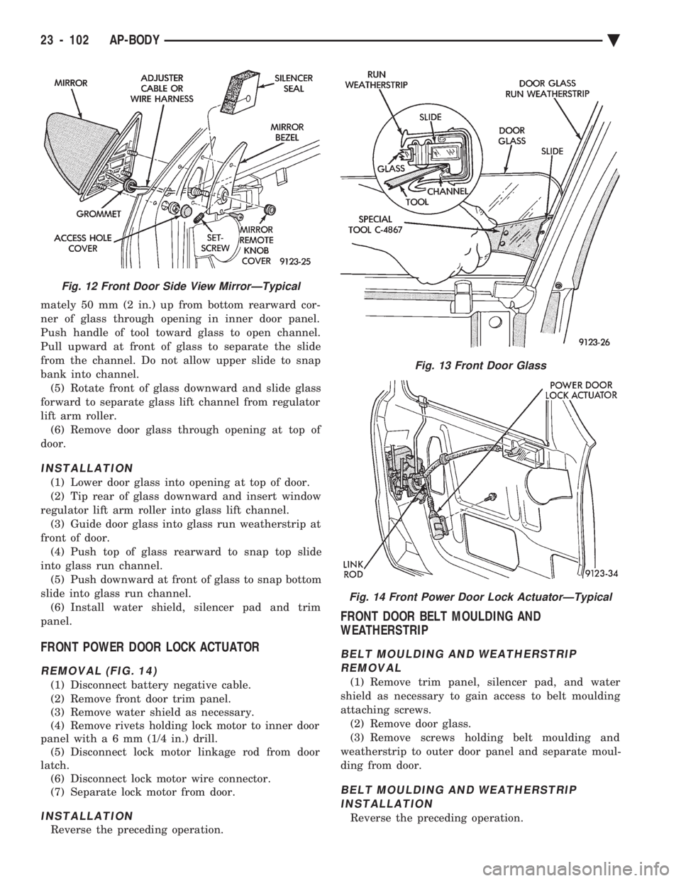
mately 50 mm (2 in.) up from bottom rearward cor-
ner of glass through opening in inner door panel.
Push handle of tool toward glass to open channel.
Pull upward at front of glass to separate the slide
from the channel. Do not allow upper slide to snap
bank into channel. (5) Rotate front of glass downward and slide glass
forward to separate glass lift channel from regulator
lift arm roller. (6) Remove door glass through opening at top of
door.
INSTALLATION
(1) Lower door glass into opening at top of door.
(2) Tip rear of glass downward and insert window
regulator lift arm roller into glass lift channel. (3) Guide door glass into glass run weatherstrip at
front of door. (4) Push top of glass rearward to snap top slide
into glass run channel. (5) Push downward at front of glass to snap bottom
slide into glass run channel. (6) Install water shield, silencer pad and trim
panel.
FRONT POWER DOOR LOCK ACTUATOR
REMOVAL (FIG. 14)
(1) Disconnect battery negative cable.
(2) Remove front door trim panel.
(3) Remove water shield as necessary.
(4) Remove rivets holding lock motor to inner door
panel wit ha6mm (1/4 in.) drill.
(5) Disconnect lock motor linkage rod from door
latch. (6) Disconnect lock motor wire connector.
(7) Separate lock motor from door.
INSTALLATION
Reverse the preceding operation.
FRONT DOOR BELT MOULDING AND
WEATHERSTRIP
BELT MOULDING AND WEATHERSTRIP
REMOVAL
(1) Remove trim panel, silencer pad, and water
shield as necessary to gain access to belt moulding
attaching screws. (2) Remove door glass.
(3) Remove screws holding belt moulding and
weatherstrip to outer door panel and separate moul-
ding from door.
BELT MOULDING AND WEATHERSTRIP INSTALLATION
Reverse the preceding operation.
Fig. 12 Front Door Side View MirrorÐTypical
Fig. 13 Front Door Glass
Fig. 14 Front Power Door Lock ActuatorÐTypical
23 - 102 AP-BODY Ä
Page 2259 of 2438
FRONT DOOR GLASS CHANNEL AND RUN
WEATHERSTRIP
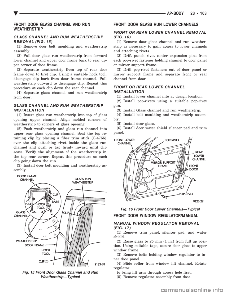
GLASS CHANNEL AND RUN WEATHERSTRIP
REMOVAL (FIG. 15)
(1) Remove door belt moulding and weatherstrip
assembly. (2) Pull door glass run weatherstrip from forward
lower channel and upper door frame back to rear up-
per corner of door frame. (3) Separate weatherstrip from top of rear door
frame down to first clip. Using a suitable hook tool,
disengage clip barb from door frame channel. Pull
weatherstrip outward to disengage clip. Repeat this
procedure at each clip down the rear channel. (4) Separate glass channel and run weatherstrip
from door.
GLASS CHANNEL AND RUN WEATHERSTRIP INSTALLATION
(1) Insert glass run weatherstrip into top of glass
opening upper channel. Align molded corners of
weatherstrip to corners of glass opening. (2) Push weatherstrip and glass run channel into
upper rear glass opening channel. Seat the top re-
taining clip by placing a fiber trim stick (C-4755)
over the clip attaching rivet inside the glass run
channel and push or tap firmly inward until clip
seats. Verify the alignment of the weatherstrip in
the top rear corner. Repeat this procedure on each
clip going down the run. (3) Install door belt moulding and weatherstrip as-
sembly.
FRONT DOOR GLASS RUN LOWER CHANNELS
FRONT OR REAR LOWER CHANNEL REMOVAL
(FIG. 16)
(1) Remove door glass channel and run weather-
strip as necessary to gain access to lower channels
and attaching rivets. (2) Drift punch rivet center expansion pins from
each pop-rivet fastener holding channel to door panel
or mirror support frame. (3) Drill pop-rivet fasteners out of door panel or
mirror support frame and separate front or rear
channel from door.
FRONT OR REAR LOWER CHANNEL INSTALLATION
(1) Install lower channel into at design location.
(2) Install pop-rivets using a suitable pop-rivet
gun. (3) Install Glass channel and run weatherstrip.
(4) Install belt moulding and weatherstrip assem-
bly. (5) Install door glass.
(6) Install door water shield silencer pad and trim
panel.
FRONT DOOR WINDOW REGULATOR/MANUAL
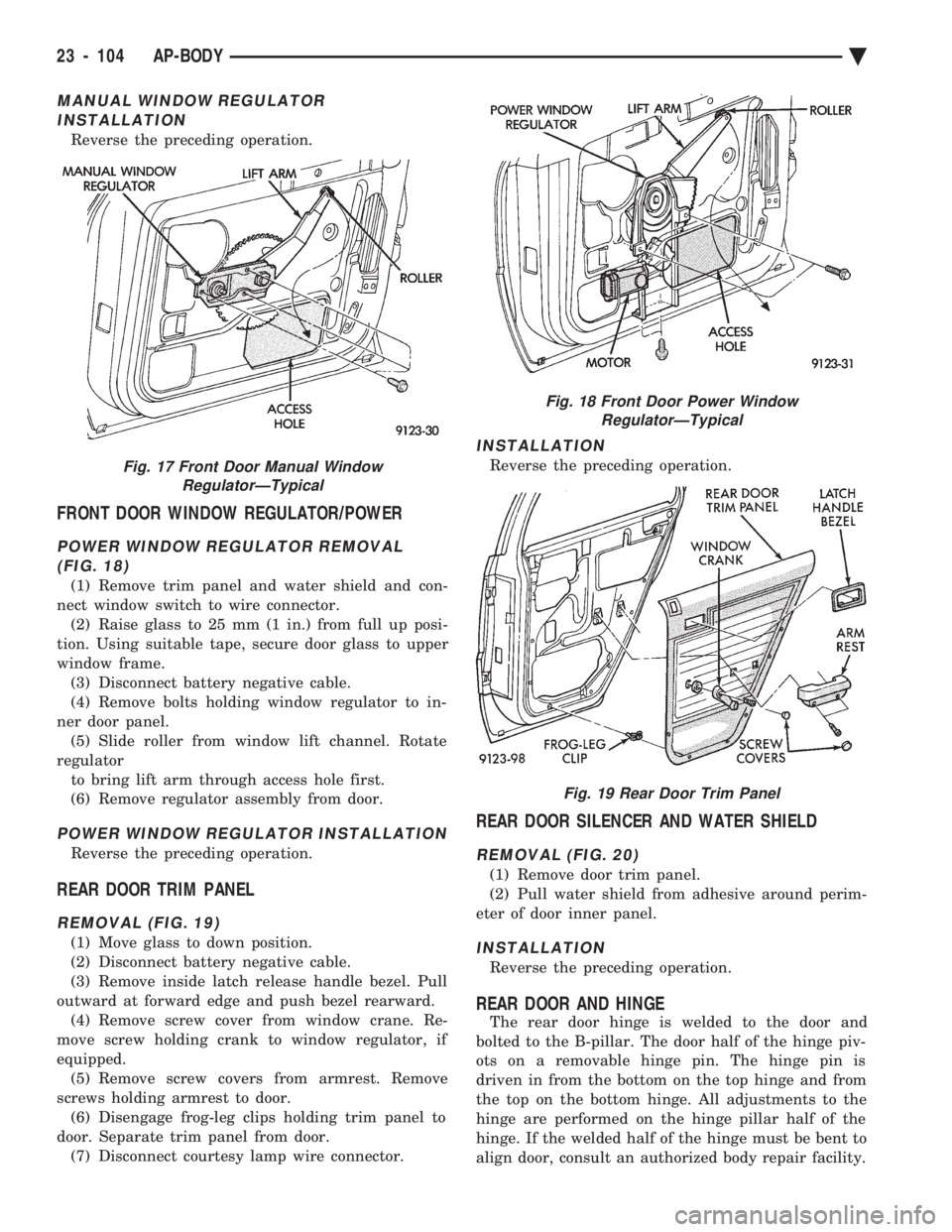
MANUAL WINDOW REGULATOR REMOVAL (FIG. 17)
(1) Remove trim panel, silencer pad, and water
shield. (2) Raise glass to 25 mm (1 in.) from full up posi-
tion. Using suitable tape, secure door glass to upper
window frame. (3) Remove bolts holding window regulator to in-
ner door panel. (4) Slide roller from window lift channel. Rotate
regulator to bring lift arm through access hole first.
(5) Remove regulator assembly from door.
Fig. 15 Front Door Glass Channel and Run WeatherstripÐTypical
Fig. 16 Front Door Lower ChannelsÐTypical
Ä AP-BODY 23 - 103
Page 2260 of 2438
MANUAL WINDOW REGULATOR INSTALLATION
Reverse the preceding operation.
FRONT DOOR WINDOW REGULATOR/POWER
POWER WINDOW REGULATOR REMOVAL(FIG. 18)
(1) Remove trim panel and water shield and con-
nect window switch to wire connector. (2) Raise glass to 25 mm (1 in.) from full up posi-
tion. Using suitable tape, secure door glass to upper
window frame. (3) Disconnect battery negative cable.
(4) Remove bolts holding window regulator to in-
ner door panel. (5) Slide roller from window lift channel. Rotate
regulator to bring lift arm through access hole first.
(6) Remove regulator assembly from door.
POWER WINDOW REGULATOR INSTALLATION
Reverse the preceding operation.
REAR DOOR TRIM PANEL
REMOVAL (FIG. 19)
(1) Move glass to down position.
(2) Disconnect battery negative cable.
(3) Remove inside latch release handle bezel. Pull
outward at forward edge and push bezel rearward. (4) Remove screw cover from window crane. Re-
move screw holding crank to window regulator, if
equipped. (5) Remove screw covers from armrest. Remove
screws holding armrest to door. (6) Disengage frog-leg clips holding trim panel to
door. Separate trim panel from door. (7) Disconnect courtesy lamp wire connector.
INSTALLATION
Reverse the preceding operation.
REAR DOOR SILENCER AND WATER SHIELD
REMOVAL (FIG. 20)
(1) Remove door trim panel.
(2) Pull water shield from adhesive around perim-
eter of door inner panel.
INSTALLATION
Reverse the preceding operation.
REAR DOOR AND HINGE
The rear door hinge is welded to the door and
bolted to the B-pillar. The door half of the hinge piv-
ots on a removable hinge pin. The hinge pin is
driven in from the bottom on the top hinge and from
the top on the bottom hinge. All adjustments to the
hinge are performed on the hinge pillar half of the
hinge. If the welded half of the hinge must be bent to
align door, consult an authorized body repair facility.
Fig. 17 Front Door Manual Window RegulatorÐTypical
Fig. 18 Front Door Power WindowRegulatorÐTypical
Fig. 19 Rear Door Trim Panel
23 - 104 AP-BODY Ä