lock CHEVROLET PLYMOUTH ACCLAIM 1993 Service Manual
[x] Cancel search | Manufacturer: CHEVROLET, Model Year: 1993, Model line: PLYMOUTH ACCLAIM, Model: CHEVROLET PLYMOUTH ACCLAIM 1993Pages: 2438, PDF Size: 74.98 MB
Page 1585 of 2438
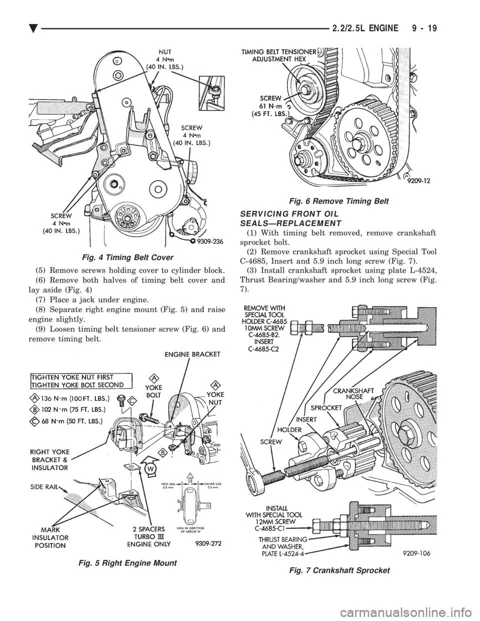
(5) Remove screws holding cover to cylinder block.
(6) Remove both halves of timing belt cover and
lay aside (Fig. 4) (7) Place a jack under engine.
(8) Separate right engine mount (Fig. 5) and raise
engine slightly. (9) Loosen timing belt tensioner screw (Fig. 6) and
remove timing belt.
SERVICING FRONT OIL SEALSÐREPLACEMENT
(1) With timing belt removed, remove crankshaft
sprocket bolt. (2) Remove crankshaft sprocket using Special Tool
C-4685, Insert and 5.9 inch long screw (Fig. 7). (3) Install crankshaft sprocket using plate L-4524,
Thrust Bearing/washer and 5.9 inch long screw (Fig.
7).
Fig. 4 Timing Belt Cover
Fig. 7 Crankshaft SprocketFig. 5 Right Engine Mount
Fig. 6 Remove Timing Belt
Ä 2.2/2.5L ENGINE 9 - 19
Page 1587 of 2438
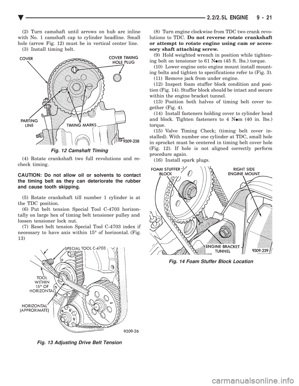
(2) Turn camshaft until arrows on hub are inline
with No. 1 camshaft cap to cylinder headline. Small
hole (arrow Fig. 12) must be in vertical center line. (3) Install timing belt.
(4) Rotate crankshaft two full revolutions and re-
check timing.
CAUTION: Do not allow oil or solvents to contact
the timing belt as they can deteriorate the rubber
and cause tooth skipping.
(5) Rotate crankshaft till number 1 cylinder is at
the TDC position. (6) Put belt tension Special Tool C-4703 horizon-
tally on large hex of timing belt tensioner pulley and
loosen tensioner lock nut. (7) Reset belt tension Special Tool C-4703 index if
necessary to have axis within 15É of horizontal. (Fig.
13) (8) Turn engine clockwise from TDC two crank revo-
lutions to TDC. Do not reverse rotate crankshaft
or attempt to rotate engine using cam or acces-
sory shaft attaching screw. (9) Hold weighted wrench in position while tighten-
ing bolt on tensioner to 61 N Im (45 ft. lbs.) torque.
(10) Lower engine onto engine mount install mount-
ing bolts and tighten to specifications refer to (Fig. 3). (11) Remove jack from under engine.
(12) Inspect foam stuffer block condition and posi-
tion (Fig. 14). Stuffer block should be intact and secure
within the engine bracket tunnel. (13) Position both halves of timing belt cover to-
gether (Fig. 4). (14) Install fasteners holding cover to cylinder head
and block. Tighten fasteners to 4 N Im (40 in. lbs.)
torque. (15) Valve Timing Check; (timing belt cover in-
stalled). With number one cylinder at TDC, small hole
in sprocket must be centered in timing belt cover hole
(Fig. 12). If hole is not aligned correctly perform
procedure again. (16) Install spark plugs.
Fig. 12 Camshaft Timing
Fig. 13 Adjusting Drive Belt Tension
Fig. 14 Foam Stuffer Block Location
Ä 2.2/2.5L ENGINE 9 - 21
Page 1590 of 2438
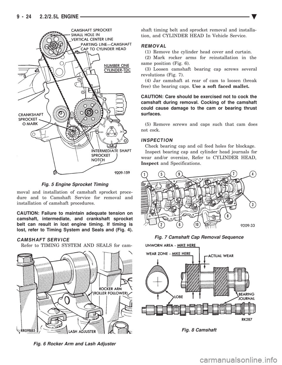
moval and installation of camshaft sprocket proce-
dure and to Camshaft Service for removal and
installation of camshaft procedures.
CAUTION: Failure to maintain adequate tension on
camshaft, intermediate, and crankshaft sprocket
belt can result in lost engine timing. If timing is
lost, refer to Timing System and Seals and (Fig. 4).
CAMSHAFT SERVICE
Refer to TIMING SYSTEM AND SEALS for cam- shaft timing belt and sprocket removal and installa-
tion, and CYLINDER HEAD In Vehicle Service.
REMOVAL
(1) Remove the cylinder head cover and curtain.
(2) Mark rocker arms for reinstallation in the
same position (Fig. 6). (3) Loosen camshaft bearing cap screws several
revolutions (Fig. 7). (4) Jar camshaft at rear of cam to loosen (break
free) the bearing caps. Use a soft faced mallet.
CAUTION: Care should be exercised not to cock the
camshaft during removal. Cocking of the camshaft
could cause damage to the cam or bearing thrust
surfaces.
(5) Remove screws and caps such that cam does
not cock.
INSPECTION
Check bearing cap and oil feed holes for blockage.
Inspect bearing cap and cylinder head journals for
wear and/or oversize, Refer to CYLINDER HEAD,
Inspect and Specifications.
Fig. 5 Engine Sprocket Timing
Fig. 6 Rocker Arm and Lash Adjuster
Fig. 7 Camshaft Cap Removal Sequence
Fig. 8 Camshaft
9 - 24 2.2/2.5L ENGINE Ä
Page 1592 of 2438
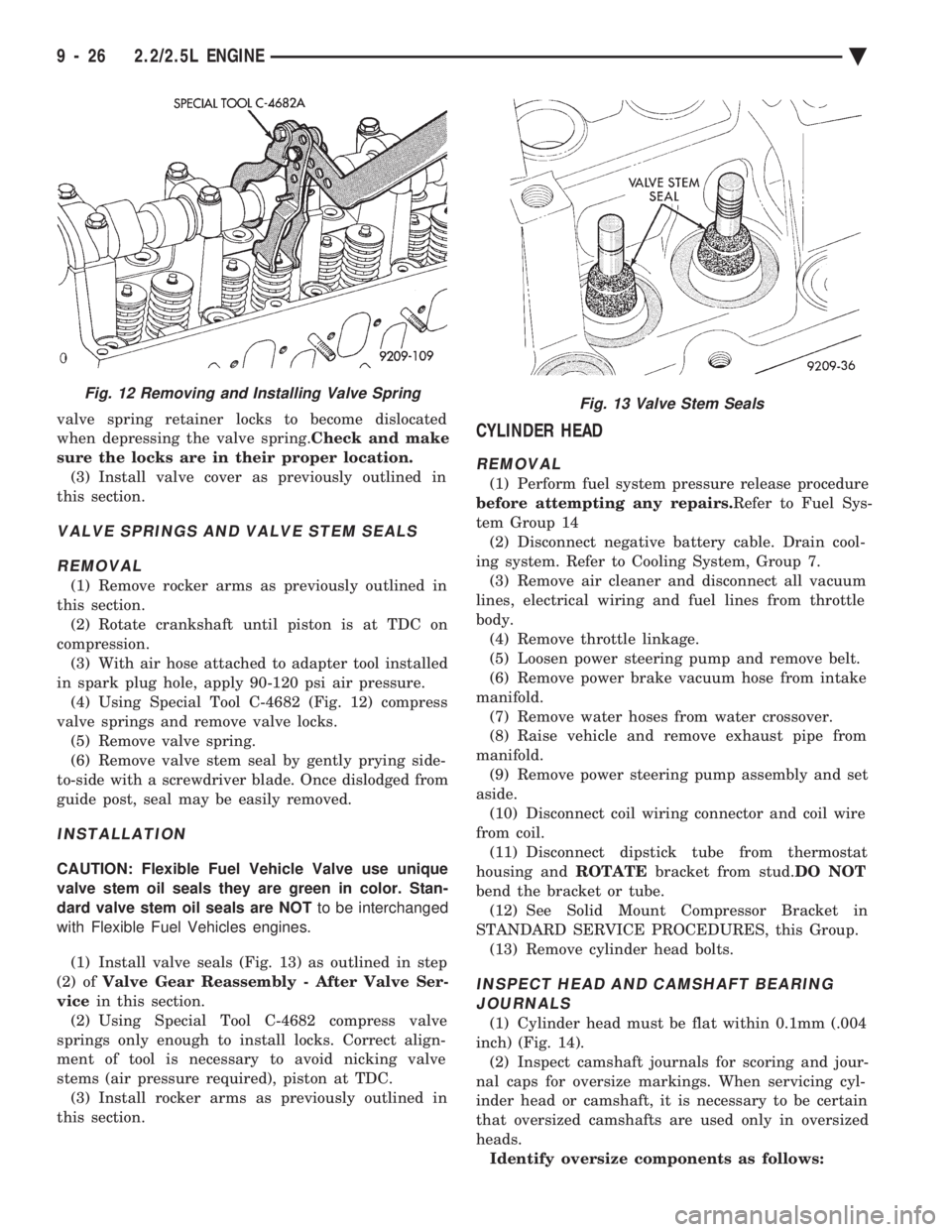
valve spring retainer locks to become dislocated
when depressing the valve spring. Check and make
sure the locks are in their proper location. (3) Install valve cover as previously outlined in
this section.
VALVE SPRINGS AND VALVE STEM SEALS
REMOVAL
(1) Remove rocker arms as previously outlined in
this section. (2) Rotate crankshaft until piston is at TDC on
compression. (3) With air hose attached to adapter tool installed
in spark plug hole, apply 90-120 psi air pressure. (4) Using Special Tool C-4682 (Fig. 12) compress
valve springs and remove valve locks. (5) Remove valve spring.
(6) Remove valve stem seal by gently prying side-
to-side with a screwdriver blade. Once dislodged from
guide post, seal may be easily removed.
INSTALLATION
CAUTION: Flexible Fuel Vehicle Valve use unique
valve stem oil seals they are green in color. Stan-
dard valve stem oil seals are NOT to be interchanged
with Flexible Fuel Vehicles engines.
(1) Install valve seals (Fig. 13) as outlined in step
(2) of Valve Gear Reassembly - After Valve Ser-
vice in this section.
(2) Using Special Tool C-4682 compress valve
springs only enough to install locks. Correct align-
ment of tool is necessary to avoid nicking valve
stems (air pressure required), piston at TDC. (3) Install rocker arms as previously outlined in
this section.
CYLINDER HEAD
REMOVAL
(1) Perform fuel system pressure release procedure
before attempting any repairs. Refer to Fuel Sys-
tem Group 14 (2) Disconnect negative battery cable. Drain cool-
ing system. Refer to Cooling System, Group 7. (3) Remove air cleaner and disconnect all vacuum
lines, electrical wiring and fuel lines from throttle
body. (4) Remove throttle linkage.
(5) Loosen power steering pump and remove belt.
(6) Remove power brake vacuum hose from intake
manifold. (7) Remove water hoses from water crossover.
(8) Raise vehicle and remove exhaust pipe from
manifold. (9) Remove power steering pump assembly and set
aside. (10) Disconnect coil wiring connector and coil wire
from coil. (11) Disconnect dipstick tube from thermostat
housing and ROTATEbracket from stud. DO NOT
bend the bracket or tube. (12) See Solid Mount Compressor Bracket in
STANDARD SERVICE PROCEDURES, this Group. (13) Remove cylinder head bolts.
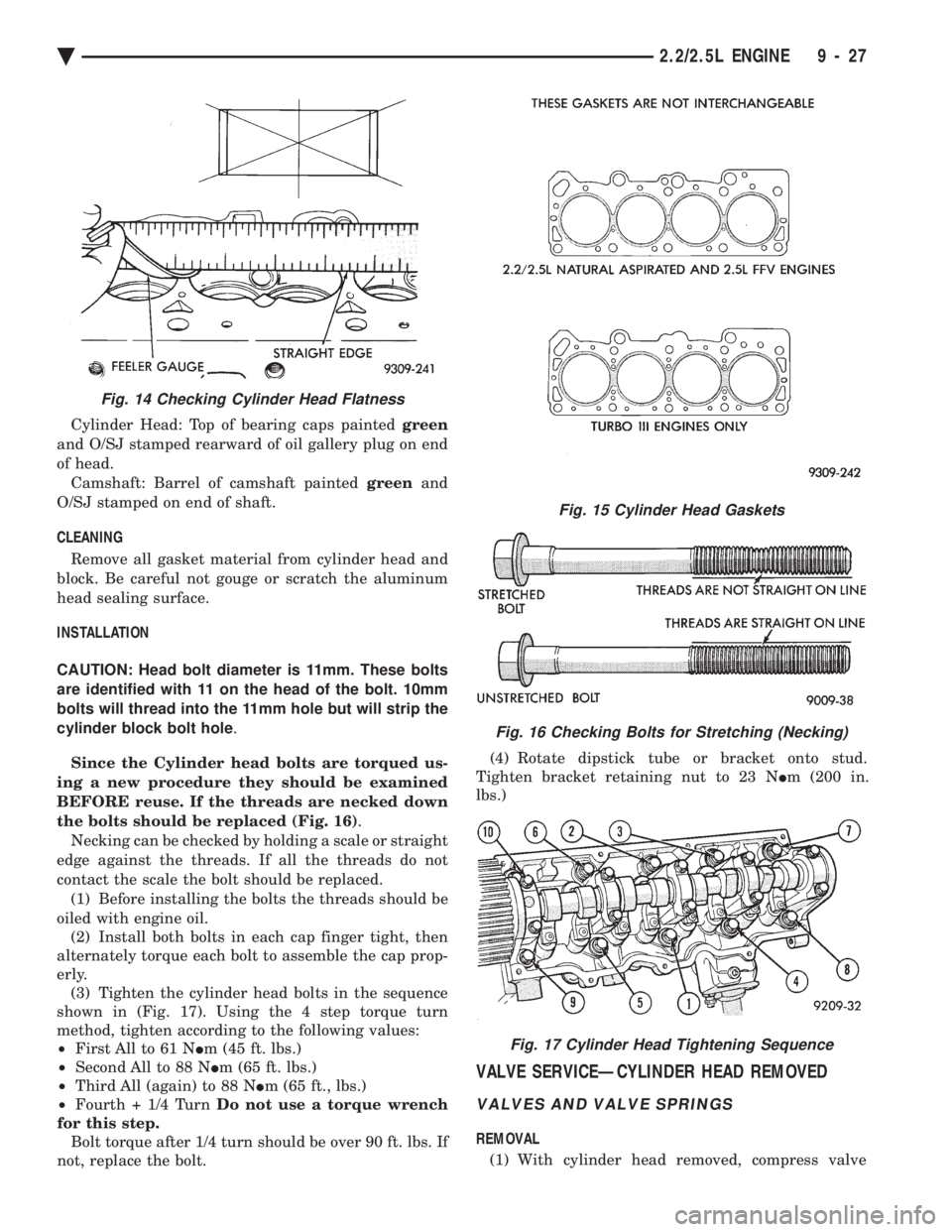
INSPECT HEAD AND CAMSHAFT BEARINGJOURNALS
(1) Cylinder head must be flat within 0.1mm (.004
inch) (Fig. 14). (2) Inspect camshaft journals for scoring and jour-
nal caps for oversize markings. When servicing cyl-
inder head or camshaft, it is necessary to be certain
that oversized camshafts are used only in oversized
heads. Identify oversize components as follows:
Fig. 12 Removing and Installing Valve SpringFig. 13 Valve Stem Seals
9 - 26 2.2/2.5L ENGINE Ä
Page 1593 of 2438
Cylinder Head: Top of bearing caps painted green
and O/SJ stamped rearward of oil gallery plug on end
of head. Camshaft: Barrel of camshaft painted greenand
O/SJ stamped on end of shaft.
CLEANING
Remove all gasket material from cylinder head and
block. Be careful not gouge or scratch the aluminum
head sealing surface.
INSTALLATION
CAUTION: Head bolt diameter is 11mm. These bolts
are identified with 11 on the head of the bolt. 10mm
bolts will thread into the 11mm hole but will strip the
cylinder block bolt hole .
Since the Cylinder head bolts are torqued us-
ing a new procedure they should be examined
BEFORE reuse. If the threads are necked down
the bolts should be replaced (Fig. 16) .
Necking can be checked by holding a scale or straight
edge against the threads. If all the threads do not
contact the scale the bolt should be replaced. (1) Before installing the bolts the threads should be
oiled with engine oil. (2) Install both bolts in each cap finger tight, then
alternately torque each bolt to assemble the cap prop-
erly. (3) Tighten the cylinder head bolts in the sequence
shown in (Fig. 17). Using the 4 step torque turn
method, tighten according to the following values:
² First All to 61 N Im (45 ft. lbs.)
² Second All to 88 N Im (65 ft. lbs.)
² Third All (again) to 88 N Im (65 ft., lbs.)
² Fourth + 1/4 Turn Do not use a torque wrench
for this step. Bolt torque after 1/4 turn should be over 90 ft. lbs. If
not, replace the bolt. (4) Rotate dipstick tube or bracket onto stud.
Tighten bracket retaining nut to 23 N Im (200 in.
lbs.)
VALVE SERVICEÐCYLINDER HEAD REMOVED
VALVES AND VALVE SPRINGS
REMOVAL
(1) With cylinder head removed, compress valve
Fig. 15 Cylinder Head Gaskets
Fig. 16 Checking Bolts for Stretching (Necking)
Fig. 17 Cylinder Head Tightening Sequence
Fig. 14 Checking Cylinder Head Flatness
Ä 2.2/2.5L ENGINE 9 - 27
Page 1594 of 2438
springs using Tool C-3422-B. (2) Remove valve retaining locks, valve spring re-
tainers, valve stem seals and valve springs. (3) Before removing valves, remove any burrs
from valve stem lock grooves to prevent damage
to the valve guides. Identify valves to insure instal-
lation in original location.
VALVE INSPECTION (1) Clean valves thoroughly and discard burned,
warped and cracked valves. (2) Measure valve stems for wear.
(3) If valve stems are worn more than 0.05 mm (.002
inch.) replace valve.
VALVE GUIDES
(1) Remove carbon and varnish deposits from inside
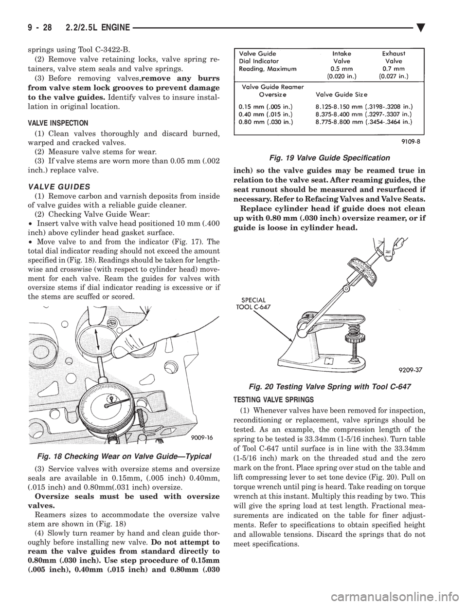
of valve guides with a reliable guide cleaner. (2) Checking Valve Guide Wear:
² Insert valve with valve head positioned 10 mm (.400
inch) above cylinder head gasket surface.
²
Move valve to and from the indicator (Fig. 17). The
total dial indicator reading should not exceed the amount
specified in (Fig. 18). Readings should be taken for length-
wise and crosswise (with respect to cylinder head) move-
ment for each valve. Ream the guides for valves with
oversize stems if dial indicator reading is excessive or if
the stems are scuffed or scored.
(3) Service valves with oversize stems and oversize
seals are available in 0.15mm, (.005 inch) 0.40mm,
(.015 inch) and 0.80mm(.031 inch) oversize. Oversize seals must be used with oversize
valves. Reamers sizes to accommodate the oversize valve
stem are shown in (Fig. 18)
(4) Slowly turn reamer by hand and clean guide thor-
oughly before installing new valve. Do not attempt to
ream the valve guides from standard directly to
0.80mm (.030 inch). Use step procedure of 0.15mm
(.005 inch), 0.40mm (.015 inch) and 0.80mm (.030 inch) so the valve guides may be reamed true in
relation to the valve seat. After reaming guides, the
seat runout should be measured and resurfaced if
necessary. Refer to Refacing Valves and Valve Seats.
Replace cylinder head if guide does not clean
up with 0.80 mm (.030 inch) oversize reamer, or if
guide is loose in cylinder head.
TESTING VALVE SPRINGS
(1) Whenever valves have been removed for inspection,
reconditioning or replacement, valve springs should be
tested. As an example, the compression length of the
spring to be tested is 33.34mm (1-5/16 inches). Turn table
of Tool C-647 until surface is in line with the 33.34mm
(1-5/16 inch) mark on the threaded stud and the zero
mark on the front. Place spring over stud on the table and
lift compressing lever to set tone device (Fig. 20). Pull on
torque wrench until ping is heard. Take reading on torque
wrench at this instant. Multiply this reading by two. This
will give the spring load at test length. Fractional mea-
surements are indicated on the table for finer adjust-
ments. Refer to specifications to obtain specified height
and allowable tensions. Discard the springs that do not
meet specifications.
Fig. 18 Checking Wear on Valve GuideÐTypical
Fig. 19 Valve Guide Specification
Fig. 20 Testing Valve Spring with Tool C-647
9 - 28 2.2/2.5L ENGINE Ä
Page 1596 of 2438
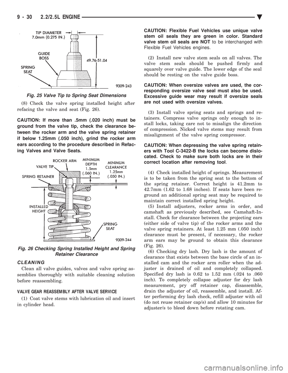
(8) Check the valve spring installed height after
refacing the valve and seat (Fig. 26).
CAUTION: If more than .5mm (.020 inch) must be
ground from the valve tip, check the clearance be-
tween the rocker arm and the valve spring retainer
if below 1.25mm (.050 inch), grind the rocker arm
ears according to the procedure described in Refac-
ing Valves and Valve Seats.
CLEANING
Clean all valve guides, valves and valve spring as-
semblies thoroughly with suitable cleaning solution
before reassembling.
VALVE GEAR REASSEMBLY AFTER VALVE SERVICE (1) Coat valve stems with lubrication oil and insert
in cylinder head. CAUTION: Flexible Fuel Vehicles use unique valve
stem oil seals they are green in color. Standard
valve stem oil seals are NOT to be interchanged with
Flexible Fuel Vehicles engines.
(2) Install new valve stem seals on all valves. The
valve stem seals should be pushed firmly and
squarely over valve guide. The lower edge of the seal
should be resting on the valve guide boss.
CAUTION: When oversize valves are used, the cor-
responding oversize valve seal must also be used.
Excessive guide wear may result if oversize seals
are not used with oversize valves.
(3) Install valve spring seats and springs and re-
tainers. Compress valve springs only enough to in-
stall locks, taking care not to misalign the direction
of compression. Nicked valve stems may result from
misalignment of the valve spring compressor.
CAUTION: When depressing the valve spring retain-
ers with Tool C-3422-B the locks can become dislo-
cated. Check to make sure both locks are in their
correct location after removing tool .
(4) Check installed height of springs. Measurement
is to be taken from the spring seat to the bottom of
the spring retainer. Correct height is 41.2mm to
42.7mm (1.62 to 1.68 inches). If seats have been re-
ground an additional spring seat may be required to
maintain correct installed spring height. (5) Install adjusters, rocker arms in order, and
camshaft as previously described, see Camshaft-In-
stall. Check for clearance between the projecting ears
(either side of valve tip) of the rocker arms and the
valve spring retainers. At least 1.25 mm (.050 inch)
clearance must be present, if necessary, the rocker
arm ears may be ground to obtain this clearance
(Fig. 26). (6) Checking dry lash. Dry lash is the amount of
clearance that exists between the base circle of an in-
stalled cam and the rocker arm roller when the ad-
juster is drained of oil and completely collapsed.
Specified dry lash is 0.62 to 1.52 mm (.024 to .060
inch). To completely collapse adjuster for dry lash
measurement, pry off retainer cap, disassemble,
drain the adjuster of oil, reassemble, and install. Af-
ter performing dry lash check, refill adjuster with oil
(do not reuse retainer cap/s) and allow 10 minutes for
adjuster/s to bleed down before rotating cam.
Fig. 25 Valve Tip to Spring Seat Dimensions
Fig. 26 Checking Spring Installed Height and Spring Retainer Clearance
9 - 30 2.2/2.5L ENGINE Ä
Page 1600 of 2438
CAMSHAFT AND CRANKSHAFT TIMING
PROCEDURE
INSTALLATION
(1) Remove air cleaner fresh air duct.
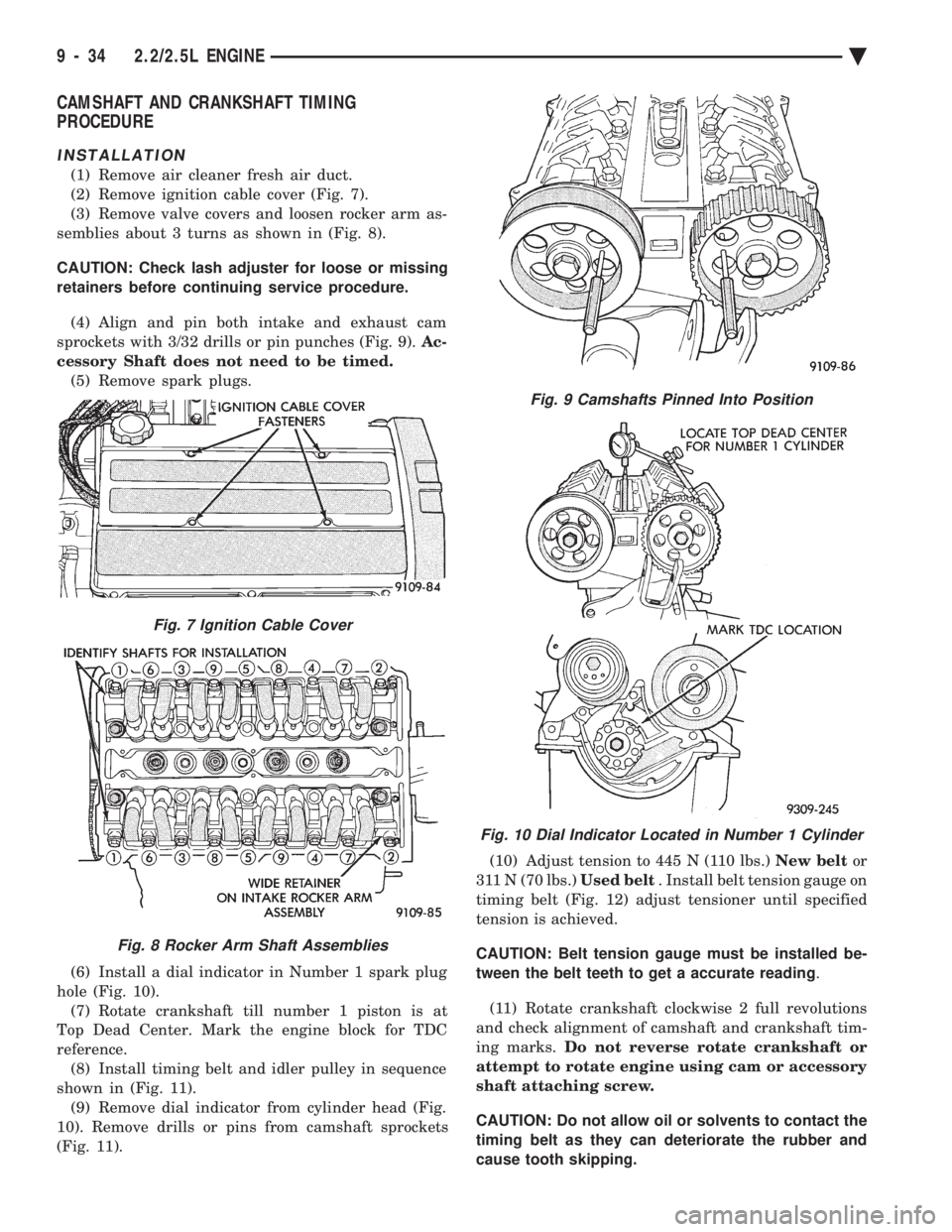
(2) Remove ignition cable cover (Fig. 7).
(3) Remove valve covers and loosen rocker arm as-
semblies about 3 turns as shown in (Fig. 8).
CAUTION: Check lash adjuster for loose or missing
retainers before continuing service procedure.
(4) Align and pin both intake and exhaust cam
sprockets with 3/32 drills or pin punches (Fig. 9). Ac-
cessory Shaft does not need to be timed. (5) Remove spark plugs.
(6) Install a dial indicator in Number 1 spark plug
hole (Fig. 10). (7) Rotate crankshaft till number 1 piston is at
Top Dead Center. Mark the engine block for TDC
reference. (8) Install timing belt and idler pulley in sequence
shown in (Fig. 11). (9) Remove dial indicator from cylinder head (Fig.
10). Remove drills or pins from camshaft sprockets
(Fig. 11). (10) Adjust tension to 445 N (110 lbs.)
New beltor
311 N (70 lbs.) Used belt. Install belt tension gauge on
timing belt (Fig. 12) adjust tensioner until specified
tension is achieved.
CAUTION: Belt tension gauge must be installed be-
tween the belt teeth to get a accurate reading .
(11) Rotate crankshaft clockwise 2 full revolutions
and check alignment of camshaft and crankshaft tim-
ing marks. Do not reverse rotate crankshaft or
attempt to rotate engine using cam or accessory
shaft attaching screw.
CAUTION: Do not allow oil or solvents to contact the
timing belt as they can deteriorate the rubber and
cause tooth skipping.
Fig. 7 Ignition Cable Cover
Fig. 8 Rocker Arm Shaft Assemblies
Fig. 9 Camshafts Pinned Into Position
Fig. 10 Dial Indicator Located in Number 1 Cylinder
9 - 34 2.2/2.5L ENGINE Ä
Page 1601 of 2438
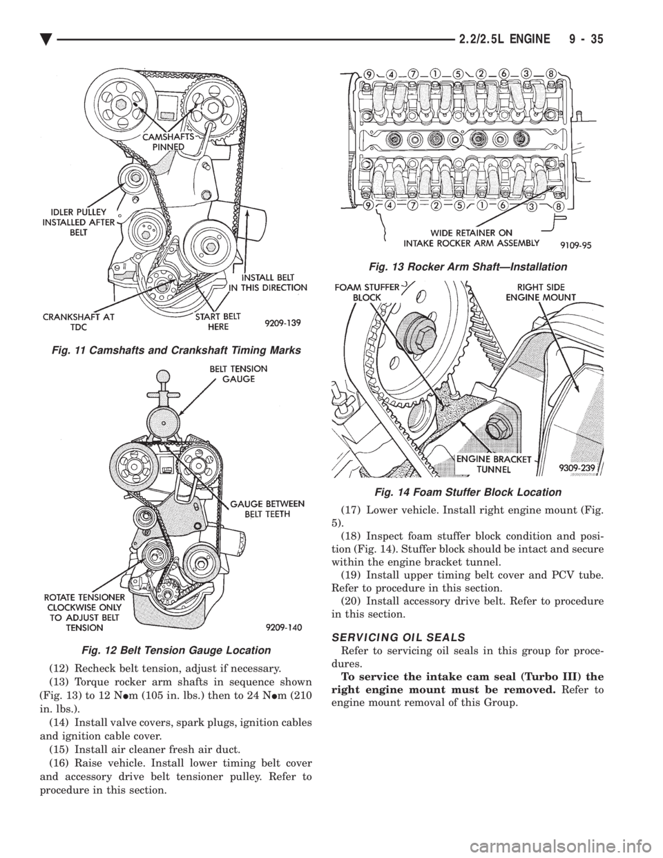
(12) Recheck belt tension, adjust if necessary.
(13) Torque rocker arm shafts in sequence shown
(Fig. 13) to 12 N Im (105 in. lbs.) then to 24 N Im (210
in. lbs.). (14) Install valve covers, spark plugs, ignition cables
and ignition cable cover. (15) Install air cleaner fresh air duct.
(16) Raise vehicle. Install lower timing belt cover
and accessory drive belt tensioner pulley. Refer to
procedure in this section. (17) Lower vehicle. Install right engine mount (Fig.
5). (18) Inspect foam stuffer block condition and posi-
tion (Fig. 14). Stuffer block should be intact and secure
within the engine bracket tunnel. (19) Install upper timing belt cover and PCV tube.
Refer to procedure in this section. (20) Install accessory drive belt. Refer to procedure
in this section.
SERVICING OIL SEALS
Refer to servicing oil seals in this group for proce-
dures. To service the intake cam seal (Turbo III) the
right engine mount must be removed. Refer to
engine mount removal of this Group.
Fig. 13 Rocker Arm ShaftÐInstallation
Fig. 14 Foam Stuffer Block Location
Fig. 11 Camshafts and Crankshaft Timing Marks
Fig. 12 Belt Tension Gauge Location
Ä 2.2/2.5L ENGINE 9 - 35
Page 1604 of 2438
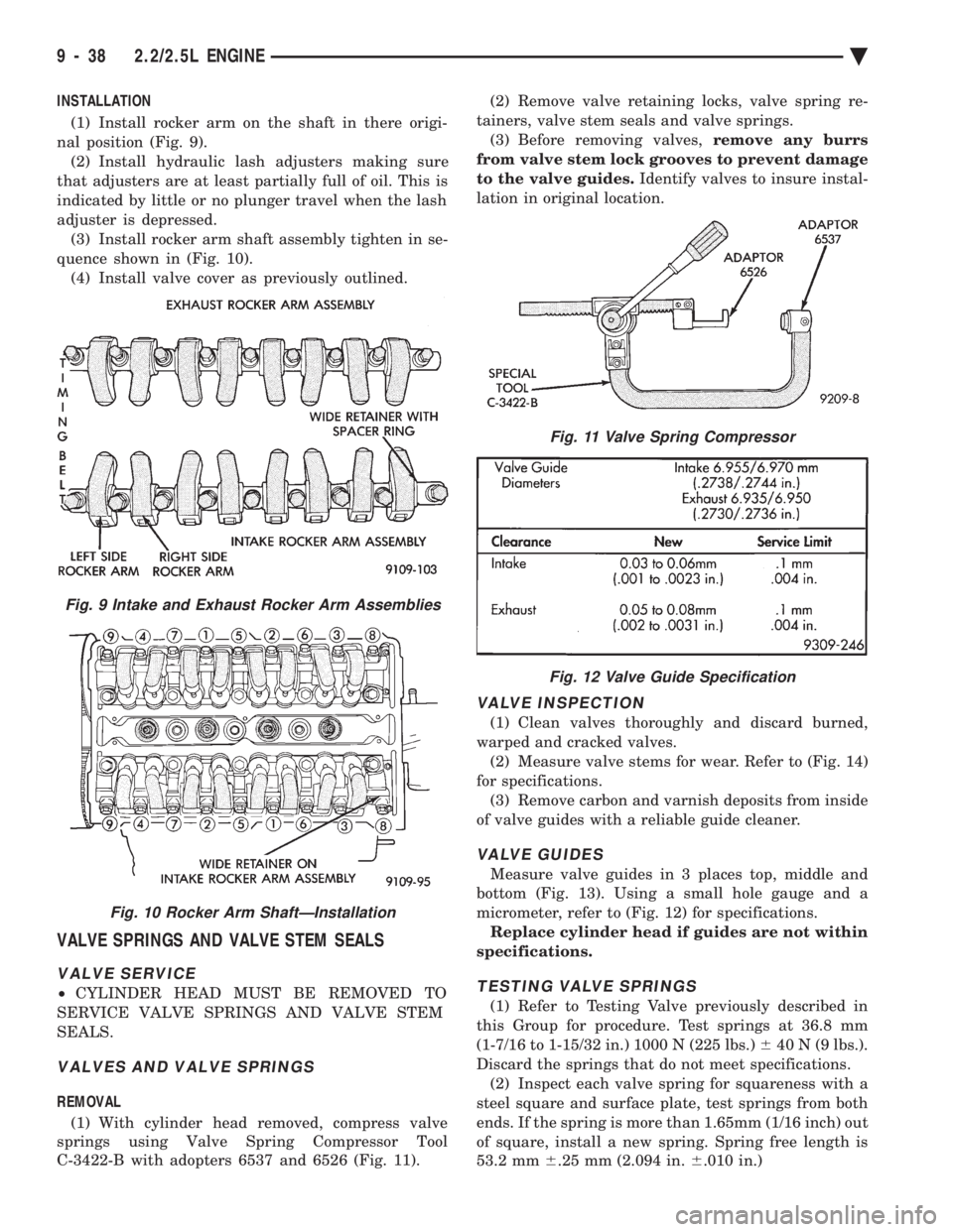
INSTALLATION (1) Install rocker arm on the shaft in there origi-
nal position (Fig. 9). (2) Install hydraulic lash adjusters making sure
that adjusters are at least partially full of oil. This is
indicated by little or no plunger travel when the lash
adjuster is depressed. (3) Install rocker arm shaft assembly tighten in se-
quence shown in (Fig. 10). (4) Install valve cover as previously outlined.
VALVE SPRINGS AND VALVE STEM SEALS
VALVE SERVICE
² CYLINDER HEAD MUST BE REMOVED TO
SERVICE VALVE SPRINGS AND VALVE STEM
SEALS.
VALVES AND VALVE SPRINGS
REMOVAL
(1) With cylinder head removed, compress valve
springs using Valve Spring Compressor Tool
C-3422-B with adopters 6537 and 6526 (Fig. 11). (2) Remove valve retaining locks, valve spring re-
tainers, valve stem seals and valve springs. (3) Before removing valves, remove any burrs
from valve stem lock grooves to prevent damage
to the valve guides. Identify valves to insure instal-
lation in original location.
VALVE INSPECTION
(1) Clean valves thoroughly and discard burned,
warped and cracked valves. (2) Measure valve stems for wear. Refer to (Fig. 14)
for specifications. (3) Remove carbon and varnish deposits from inside
of valve guides with a reliable guide cleaner.
VALVE GUIDES
Measure valve guides in 3 places top, middle and
bottom (Fig. 13). Using a small hole gauge and a
micrometer, refer to (Fig. 12) for specifications. Replace cylinder head if guides are not within
specifications.
TESTING VALVE SPRINGS
(1) Refer to Testing Valve previously described in
this Group for procedure. Test springs at 36.8 mm
(1-7/16 to 1-15/32 in.) 1000 N (225 lbs.) 640 N (9 lbs.).
Discard the springs that do not meet specifications. (2) Inspect each valve spring for squareness with a
steel square and surface plate, test springs from both
ends. If the spring is more than 1.65mm (1/16 inch) out
of square, install a new spring. Spring free length is
53.2 mm 6.25 mm (2.094 in. 6.010 in.)
Fig. 9 Intake and Exhaust Rocker Arm Assemblies
Fig. 10 Rocker Arm ShaftÐInstallation
Fig. 11 Valve Spring Compressor
Fig. 12 Valve Guide Specification
9 - 38 2.2/2.5L ENGINE Ä