lock CHEVROLET PLYMOUTH ACCLAIM 1993 Service Manual
[x] Cancel search | Manufacturer: CHEVROLET, Model Year: 1993, Model line: PLYMOUTH ACCLAIM, Model: CHEVROLET PLYMOUTH ACCLAIM 1993Pages: 2438, PDF Size: 74.98 MB
Page 2368 of 2438
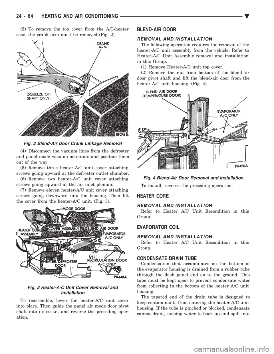
(3) To remove the top cover from the A/C-heater
case, the crank arm must be removed (Fig. 2).
(4) Disconnect the vacuum lines from the defroster
and panel mode vacuum actuators and position them
out of the way. (5) Remove three heater-A/C unit cover attaching
screws going upward at the defroster outlet chamber. (6) Remove two heater-A/C unit cover attaching
screws going upward at the air inlet plenum. (7) Remove eleven heater-A/C unit cover attaching
screws going downward into the housing. Then lift
the cover from the heater-A/C unit. (Fig. 3).
To reassemble, lower the heater-A/C unit cover
into place. Then guide the panel air mode door pivot
shaft into its socket and reverse the preceding oper-
ation.BLEND-AIR DOOR
REMOVAL AND INSTALLATION
The following operation requires the removal of the
heater-A/C unit assembly from the vehicle. Refer to
Heater-A/C Unit Assembly removal and installation
in this Group. (1) Remove Heater-A/C unit top cover.
(2) Remove the nut from bottom of the blend-air
door pivot shaft and lift the blend-air door from the
heater-A/C unit housing. (Fig. 4).
To install, reverse the preceding operation.
HEATER CORE
REMOVAL AND INSTALLATION
Refer to Heater A/C Unit Recondition in this
Group.
EVAPORATOR COIL
REMOVAL AND INSTALLATION
Refer to Heater A/C Unit Recondition in this
Group.
CONDENSATE DRAIN TUBE
Condensation that accumulates on the bottom of
the evaporator housing is drained from a rubber tube
through the dash panel and on to the ground. This
tube must be kept open to prevent condensate water
from collecting in the bottom of the heater A/C unit
housing. The tapered end of the drain tube is designed to
keep contaminants from entering the heater A/C unit
housing. If the tube is pinched or blocked, condensate
cannot drain, causing water to back up and spill into
Fig. 2 Blend-Air Door Crank Linkage Removal
Fig. 3 Heater-A/C Unit Cover Removal and Installation
Fig. 4 Blend-Air Door Removal and Installation
24 - 64 HEATING AND AIR CONDITIONING Ä
Page 2370 of 2438
AUTOMATIC TEMPERATURE CONTROL (ATC) INDEX
page page
Ambient Temperature Sensor ............... 67
ATC Computer/Control Panel ................ 66
Blend-Air Door Actuator .................... 69
Computer Aided Diagnostic Tests ............ 72
Diagnostic Trouble Code Definitions .......... 73
Diagnostic Trouble Code Service Procedures . . . 74
Erasing Diagnostic Trouble Codes ............ 83
Fresh/Recirc Door Actuator ................. 68 General InformationÐComponent Operation
.... 66
In-Car Temperature Sensor/Aspirator Assembly . . 70
Manual A/C Mode ........................ 66
Mode Door Actuator ...................... 69
NonÐComputer Aided Diagnostic Tests ....... 72
Power Module ........................... 67
Sun Sensor ............................. 71
Water Temperature Sensor ................. 71
GENERAL INFORMATIONÐCOMPONENT
OPERATION
The Automatic Temperature Control (ATC) system
lets the operator change the passenger compartment
environment. A computer, built into the control
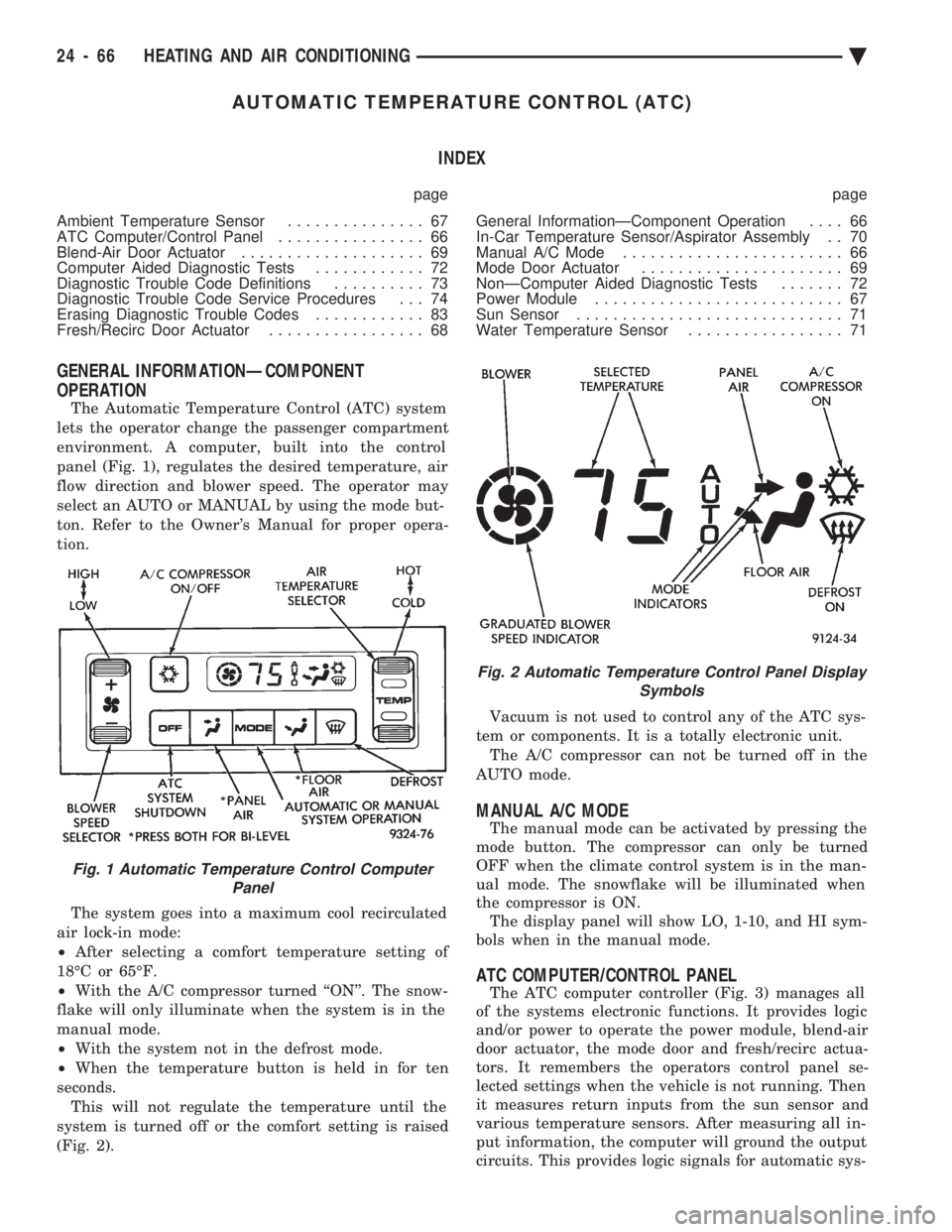
panel (Fig. 1), regulates the desired temperature, air
flow direction and blower speed. The operator may
select an AUTO or MANUAL by using the mode but-
ton. Refer to the Owner's Manual for proper opera-
tion.
The system goes into a maximum cool recirculated
air lock-in mode:
² After selecting a comfort temperature setting of
18ÉC or 65ÉF.
² With the A/C compressor turned ``ON''. The snow-
flake will only illuminate when the system is in the
manual mode.
² With the system not in the defrost mode.
² When the temperature button is held in for ten
seconds. This will not regulate the temperature until the
system is turned off or the comfort setting is raised
(Fig. 2). Vacuum is not used to control any of the ATC sys-
tem or components. It is a totally electronic unit. The A/C compressor can not be turned off in the
AUTO mode.
MANUAL A/C MODE
The manual mode can be activated by pressing the
mode button. The compressor can only be turned
OFF when the climate control system is in the man-
ual mode. The snowflake will be illuminated when
the compressor is ON. The display panel will show LO, 1-10, and HI sym-
bols when in the manual mode.
ATC COMPUTER/CONTROL PANEL
The ATC computer controller (Fig. 3) manages all
of the systems electronic functions. It provides logic
and/or power to operate the power module, blend-air
door actuator, the mode door and fresh/recirc actua-
tors. It remembers the operators control panel se-
lected settings when the vehicle is not running. Then
it measures return inputs from the sun sensor and
various temperature sensors. After measuring all in-
put information, the computer will ground the output
circuits. This provides logic signals for automatic sys-
Fig. 1 Automatic Temperature Control Computer Panel
Fig. 2 Automatic Temperature Control Panel Display Symbols
24 - 66 HEATING AND AIR CONDITIONING Ä
Page 2373 of 2438
To install, reverse the preceding operation.
BLEND-AIR DOOR ACTUATOR
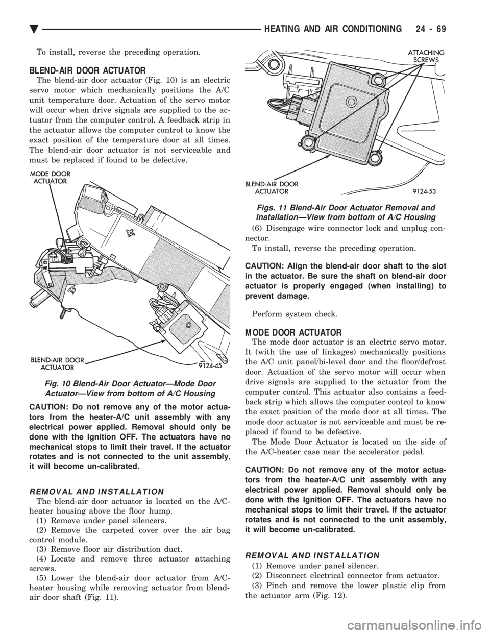
The blend-air door actuator (Fig. 10) is an electric
servo motor which mechanically positions the A/C
unit temperature door. Actuation of the servo motor
will occur when drive signals are supplied to the ac-
tuator from the computer control. A feedback strip in
the actuator allows the computer control to know the
exact position of the temperature door at all times.
The blend-air door actuator is not serviceable and
must be replaced if found to be defective.
CAUTION: Do not remove any of the motor actua-
tors from the heater-A/C unit assembly with any
electrical power applied. Removal should only be
done with the Ignition OFF. The actuators have no
mechanical stops to limit their travel. If the actuator
rotates and is not connected to the unit assembly,
it will become un-calibrated.
REMOVAL AND INSTALLATION
The blend-air door actuator is located on the A/C-
heater housing above the floor hump. (1) Remove under panel silencers.
(2) Remove the carpeted cover over the air bag
control module. (3) Remove floor air distribution duct.
(4) Locate and remove three actuator attaching
screws. (5) Lower the blend-air door actuator from A/C-
heater housing while removing actuator from blend-
air door shaft (Fig. 11). (6) Disengage wire connector lock and unplug con-
nector. To install, reverse the preceding operation.
CAUTION: Align the blend-air door shaft to the slot
in the actuator. Be sure the shaft on blend-air door
actuator is properly engaged (when installing) to
prevent damage.
Perform system check.
MODE DOOR ACTUATOR
The mode door actuator is an electric servo motor.
It (with the use of linkages) mechanically positions
the A/C unit panel/bi-level door and the floor/defrost
door. Actuation of the servo motor will occur when
drive signals are supplied to the actuator from the
computer control. This actuator also contains a feed-
back strip which allows the computer control to know
the exact position of the mode door at all times. The
mode door actuator is not serviceable and must be re-
placed if found to be defective. The Mode Door Actuator is located on the side of
the A/C-heater case near the accelerator pedal.
CAUTION: Do not remove any of the motor actua-
tors from the heater-A/C unit assembly with any
electrical power applied. Removal should only be
done with the Ignition OFF. The actuators have no
mechanical stops to limit their travel. If the actuator
rotates and is not connected to the unit assembly,
it will become un-calibrated.
REMOVAL AND INSTALLATION
(1) Remove under panel silencer.
(2) Disconnect electrical connector from actuator.
(3) Pinch and remove the lower plastic clip from
the actuator arm (Fig. 12).
Fig. 10 Blend-Air Door ActuatorÐMode Door ActuatorÐView from bottom of A/C Housing
Figs. 11 Blend-Air Door Actuator Removal andInstallationÐView from bottom of A/C Housing
Ä HEATING AND AIR CONDITIONING 24 - 69
Page 2375 of 2438
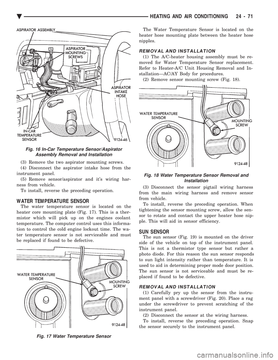
(3) Remove the two aspirator mounting screws.
(4) Disconnect the aspirator intake hose from the
instrument panel. (5) Remove sensor/aspirator and it's wiring har-
ness from vehicle. To install, reverse the preceding operation.
WATER TEMPERATURE SENSOR
The water temperature sensor is located on the
heater core mounting plate (Fig. 17). This is a ther-
mistor which will pick up on the engines coolant
temperature. The computer control uses this informa-
tion to control the cold engine lockout time. The wa-
ter temperature sensor is not serviceable and must
be replaced if found to be defective. The Water Temperature Sensor is located on the
heater hose mounting plate between the heater hose
nipples.
REMOVAL AND INSTALLATION
(1) The A/C-heater housing assembly must be re-
moved for Water Temperature Sensor replacement.
Refer to Heater-A/C Unit Housing Removal and In-
stallationÐAC/AY Body for procedures. (2) Remove sensor mounting screw (Fig. 18).
(3) Disconnect the sensor pigtail wiring harness
from the main wiring harness and remove sensor
from vehicle. To install, reverse the preceding operation. When
tightening the sensor mounting screw, allow the sen-
sor to rotate and contact the upper heater hose nip-
ple. This will aid in sensor efficiency.
SUN SENSOR
The sun sensor (Fig. 19) is mounted on the driver
side of the vehicle on top of the instrument panel.
This is not a thermistor type sensor but rather a
photo diode. For this reason the sun sensor responds
to sun light intensity rather than temperature. It is
used to aid in determining proper mode door position.
The sun sensor is not serviceable and must be re-
placed if found to be defective.
REMOVAL AND INSTALLATION
(1) Carefully pry up the sensor from the instru-
ment panel with a screwdriver (Fig. 20). Place a rag
under the screwdriver to prevent scratching of the
instrument panel. (2) Disconnect the sensor at the wiring harness.
To install, reverse the preceding operation. Snap
the sensor securely to the instrument panel.
Fig. 16 In-Car Temperature Sensor/Aspirator Assembly Removal and Installation
Fig. 17 Water Temperature Sensor
Fig. 18 Water Temperature Sensor Removal and Installation
Ä HEATING AND AIR CONDITIONING 24 - 71
Page 2403 of 2438
POSITIVE CRANKCASE VENTILATION (PCV)
SYSTEMS
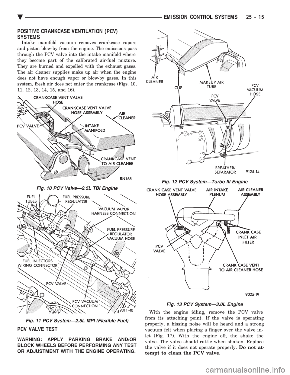
Intake manifold vacuum removes crankcase vapors
and piston blow-by from the engine. The emissions pass
through the PCV valve into the intake manifold where
they become part of the calibrated air-fuel mixture.
They are burned and expelled with the exhaust gases.
The air cleaner supplies make up air when the engine
does not have enough vapor or blow-by gases. In this
system, fresh air does not enter the crankcase (Figs. 10,
11, 12, 13, 14, 15, and 16).
PCV VALVE TEST
WARNING: APPLY PARKING BRAKE AND/OR
BLOCK WHEELS BEFORE PERFORMING ANY TEST
OR ADJUSTMENT WITH THE ENGINE OPERATING. With the engine idling, remove the PCV valve
from its attaching point. If the valve is operating
properly, a hissing noise will be heard and a strong
vacuum felt when placing a finger over the valve in-
let (Fig. 17). With the engine off, the shake the
valve. The valve should rattle when shaken. Replace
the valve if it does not operate properly. Do not at-
tempt to clean the PCV valve.
Fig. 10 PCV ValveÐ2.5L TBI Engine
Fig. 11 PCV SystemÐ2.5L MPI (Flexible Fuel)
Fig. 12 PCV SystemÐTurbo III Engine
Fig. 13 PCV SystemÐ3.0L Engine
Ä EMISSION CONTROL SYSTEMS 25 - 15
Page 2409 of 2438
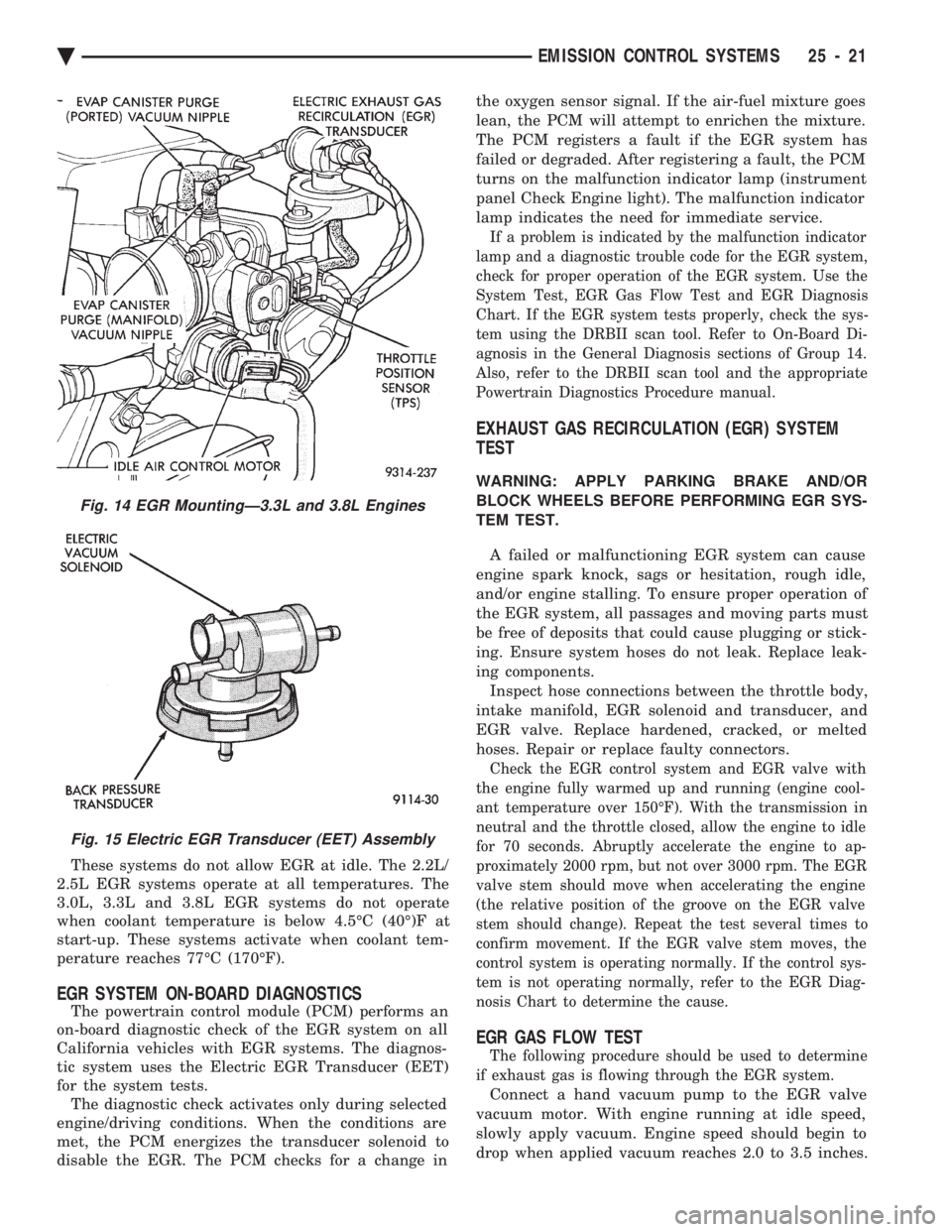
These systems do not allow EGR at idle. The 2.2L/
2.5L EGR systems operate at all temperatures. The
3.0L, 3.3L and 3.8L EGR systems do not operate
when coolant temperature is below 4.5ÉC (40É)F at
start-up. These systems activate when coolant tem-
perature reaches 77ÉC (170ÉF).
EGR SYSTEM ON-BOARD DIAGNOSTICS
The powertrain control module (PCM) performs an
on-board diagnostic check of the EGR system on all
California vehicles with EGR systems. The diagnos-
tic system uses the Electric EGR Transducer (EET)
for the system tests. The diagnostic check activates only during selected
engine/driving conditions. When the conditions are
met, the PCM energizes the transducer solenoid to
disable the EGR. The PCM checks for a change in the oxygen sensor signal. If the air-fuel mixture goes
lean, the PCM will attempt to enrichen the mixture.
The PCM registers a fault if the EGR system has
failed or degraded. After registering a fault, the PCM
turns on the malfunction indicator lamp (instrument
panel Check Engine light). The malfunction indicator
lamp indicates the need for immediate service.
If a problem is indicated by the malfunction indicator
lamp and a diagnostic trouble code for the EGR system,
check for proper operation of the EGR system. Use the
System Test, EGR Gas Flow Test and EGR Diagnosis
Chart. If the EGR system tests properly, check the sys-
tem using the DRBII scan tool. Refer to On-Board Di-
agnosis in the General Diagnosis sections of Group 14.
Also, refer to the DRBII scan tool and the appropriate
Powertrain Diagnostics Procedure manual.
EXHAUST GAS RECIRCULATION (EGR) SYSTEM
TEST
WARNING: APPLY PARKING BRAKE AND/OR
BLOCK WHEELS BEFORE PERFORMING EGR SYS-
TEM TEST.
A failed or malfunctioning EGR system can cause
engine spark knock, sags or hesitation, rough idle,
and/or engine stalling. To ensure proper operation of
the EGR system, all passages and moving parts must
be free of deposits that could cause plugging or stick-
ing. Ensure system hoses do not leak. Replace leak-
ing components. Inspect hose connections between the throttle body,
intake manifold, EGR solenoid and transducer, and
EGR valve. Replace hardened, cracked, or melted
hoses. Repair or replace faulty connectors.
Check the EGR control system and EGR valve with
the engine fully warmed up and running (engine cool-
ant temperature over 150ÉF). With the transmission in
neutral and the throttle closed, allow the engine to idle
for 70 seconds. Abruptly accelerate the engine to ap-
proximately 2000 rpm, but not over 3000 rpm. The EGR
valve stem should move when accelerating the engine
(the relative position of the groove on the EGR valve
stem should change). Repeat the test several times to
confirm movement. If the EGR valve stem moves, the
control system is operating normally. If the control sys-
tem is not operating normally, refer to the EGR Diag-
nosis Chart to determine the cause.
EGR GAS FLOW TEST
The following procedure should be used to determine
if exhaust gas is flowing through the EGR system.
Connect a hand vacuum pump to the EGR valve
vacuum motor. With engine running at idle speed,
slowly apply vacuum. Engine speed should begin to
drop when applied vacuum reaches 2.0 to 3.5 inches.
Fig. 14 EGR MountingÐ3.3L and 3.8L Engines
Fig. 15 Electric EGR Transducer (EET) Assembly
Ä EMISSION CONTROL SYSTEMS 25 - 21