sensor CHEVROLET PLYMOUTH ACCLAIM 1993 Service Manual
[x] Cancel search | Manufacturer: CHEVROLET, Model Year: 1993, Model line: PLYMOUTH ACCLAIM, Model: CHEVROLET PLYMOUTH ACCLAIM 1993Pages: 2438, PDF Size: 74.98 MB
Page 2376 of 2438
NONÐCOMPUTER AIDED DIAGNOSTIC TESTS
Determine whether the operator complaint is due
to a system failure or improper operation of the ATC
system. The system will to go into a maximum heat
or cooling mode if the operator changes the tempera-
ture setting four or more degrees. Check the following:
² Coolant level
² Refrigerant charge
² Drive belt tension
² Radiator air flow
² Radiator fan operation
² Air suction of In-car Temperature Sensor/Aspirator
To check air suction of the Aspirator, place a small
piece of tissue paper over the Aspirator opening on
the instrument panel. This opening is located to the
right of the steering column. The tissue paper should
cling to the opening if system is functioning properly. Bring the engine to normal operating temperature
and proceed with Computer Aided Diagnostic Proce-
dures. Always test the entire system after each re-
pair has been performed.
COMPUTER AIDED DIAGNOSTIC TESTS
The ATC control has a computer capable of trou-
bleshooting the entire ATC system in approximately
60 seconds. The engine must be running and at nor-
mal operating temperature during the test to provide
hot coolant for the heater. During the ATC Diagnostic Test, the computer will
calibrate the Mode and Blend Door actuators.
CAUTION: Do not remove the actuators from the
heater-A/C unit assembly with power applied. Re-
moval should only be done with the Ignition OFF.
The actuators have no mechanical stops to limit the
travel. If the actuator rotates and is not connected
to the unit assembly, it will become un-calibrated.
The Diagnostic Test is capable of checking all elec-
trical signals between the ATC Control Module, ac-
tuators, sensors and blower control. The Diagnostic Test will display two types of Diag-
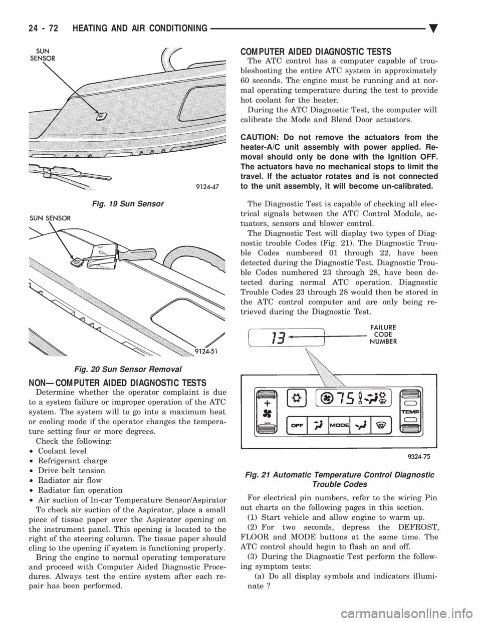
nostic trouble Codes (Fig. 21). The Diagnostic Trou-
ble Codes numbered 01 through 22, have been
detected during the Diagnostic Test. Diagnostic Trou-
ble Codes numbered 23 through 28, have been de-
tected during normal ATC operation. Diagnostic
Trouble Codes 23 through 28 would then be stored in
the ATC control computer and are only being re-
trieved during the Diagnostic Test.
For electrical pin numbers, refer to the wiring Pin
out charts on the following pages in this section. (1) Start vehicle and allow engine to warm up.
(2) For two seconds, depress the DEFROST,
FLOOR and MODE buttons at the same time. The
ATC control should begin to flash on and off. (3) During the Diagnostic Test perform the follow-
ing symptom tests: (a) Do all display symbols and indicators illumi-
nate ?
Fig. 19 Sun Sensor
Fig. 20 Sun Sensor Removal
Fig. 21 Automatic Temperature Control Diagnostic Trouble Codes
24 - 72 HEATING AND AIR CONDITIONING Ä
Page 2377 of 2438
(b) Does the blower motor operate at its highest
speed ? (c) Feel the outlet temperature. Does it get hot
and then cycle cold ? (d) Does the air flow switch from DEFROST out-
lets and then cycle to PANEL outlets?
If you can answer NO to any of these questions,
proceed to step 4, otherwise proceed to step 5. (4) If you answered NO to:
SYMPTOM A
The display symbols and indicators do not illumi-
nate. Diagnostic Trouble Codes are not displayed.
TEST
After self-diagnostic test is complete, select a mode
that will display the malfunction.
ACTION
If the ATC system operates properly, and the dis-
play does not, replace ATC control panel computer.
SYMPTOM B
The blower motor does not operate.
CAUTION: Stay clear of blower motor and power
module (PM) heat sink. Do not run system for more
than 10 minutes with PM removed from A/C unit.
TEST Check all power module and blower motor connec-
tions. Use a voltmeter to test for 12 volts (ignition)
at both ends of the fuse with ignition ON. If fuse is
good, test the green wire at the blower motor connec-
tor for 12 volts (ignition) to body ground. Turn ignition to the ON position.
With the blower motor still connected, check for 12
volts to body ground on the black/tan wire of the
blower motor two way connector. Check for 12 volts at the Power Module pin #4
(BK/TN). Check for continuity from the Power Module pin
#3 (BK) to chassis ground. Replace the Power Module.
ACTION If 12 volts is not detected, repair feed circuit. Refer
to the Front Wheel Drive Car-Wiring Diagrams Ser-
vice Manual. If 12 volts is not detected, repair wires of the
blower motor or replace the blower motor. If 12 volts is not present, repair wire from the
blower motor connector to the Power Module. If circuit is open, repair ground circuit of the Power
Module. Replace the Power Module (power transistor open).
SYMPTOM C
The outlet air temperature does not become hot
and then cycle to cold during self-test operation. Di-
agnostic Trouble Codes are not displayed.
TEST/ACTION
Make sure the blend-air door is properly attached
to the actuator. If cold air is not discharged from the outlets, check
the base A/C refrigerant system. Make sure heating operation works correctly, (wa-
ter level, thermostat, heater hoses, heater core, etc.).
SYMPTOM D
Air does not flow from DEFROST outlets and then
cycle to PANEL outlets during self-test operation.
TEST/ACTION Check linkages from the mode door actuator for
binding. Check for proper door travel in the unit.
(5) The computer will do one of two things:
² Will return to the control settings that were se-
lected before the Diagnostic Test was started. This
means the test is over. If Diagnostic Trouble Codes
did not occur, and answers to questions (a), (b), (c),
and (d) were YES, the entire system is operating cor-
rectly.
² The blower motor will stop and the computer will
flash a Diagnostic Trouble Code number from 01
through 28. Record the number and then depress the
PANEL button to advance to the next test. If the
ATC control flashes one or more codes 23 to 28, the
digits on the display will flash alternating Zeros. If
you do nothing, these codes will remain stored within
the ATC control computer. After all repairs have
been made erase fault codes. Refer to Erasing Diag-
nostic Trouble Codes 23 through 28 from ATC Con-
trol in this section. Repair all Diagnostic Trouble Codes in the order
that they have been indicated, and then retest the
system. If any blend door test fails, all remaining
blend door tests will be skipped. IF any mode door
tests fail, all remaining mode door tests will be
skipped. Diagnostic Test can be stopped at any time by de-
pressing any button other than PANEL.
DIAGNOSTIC TROUBLE CODE DEFINITIONS
Non-computer aided diagnostics should be per-
formed first. Hood of vehicle should be closed during
the diagnostic test to keep engine heat from effecting
the ambient temperature sensor. Also refer to the wiring Pin out charts.
² DIAGNOSTIC TROUBLE CODE 1
Involves the wiring or the ATC control head.
² DIAGNOSTIC TROUBLE CODES 2, 13, 14, 15,
20, and 23
Ä HEATING AND AIR CONDITIONING 24 - 73
Page 2378 of 2438
Involves the wiring, blend-air door actuator, or the
ATC control head.
² DIAGNOSTIC TROUBLE CODES 3, 16, 17, 18, 19,
and 24 Involves the wiring, mode door actuator, or the ATC
control head.
² DIAGNOSTIC TROUBLE CODE 4
Involves the wiring, blend-air door actuator, mode
door actuator, fresh/recirc. door actuator, or the ATC
control head.
² DIAGNOSTIC TROUBLE CODE 5
Involves the wiring, fresh/recirc. door actuator, or the
ATC control head.
² DIAGNOSTIC TROUBLE CODE 6
Involves the compressor circuit signal wiring, or the
ATC control head.
² DIAGNOSTIC TROUBLE CODE 7
Involves the blower wiring, power module, or the
ATC control head.
² DIAGNOSTIC TROUBLE CODES 8, 21, 22
Requires replacing the ATC control head.
² DIAGNOSTIC TROUBLE CODES 9, and 27
Involves the wiring, sun sensor, or the ATC control
head.
² DIAGNOSTIC TROUBLE CODES 10, and 28
Involves the wiring, water temperature sensor, or the
ATC control head.
² DIAGNOSTIC TROUBLE CODES 11, and 25
Involves the wiring, ambient temperature sensor, or
the ATC control head.
² DIAGNOSTIC TROUBLE CODES 12, and 26
Involves the wiring, in-car temperature
sensor/aspirator, or the ATC control head.
DIAGNOSTIC TROUBLE CODE SERVICE PROCE-
DURES
The control keyboard will not function if pins
7, 9, 17, 19, or 20 of the 21-way wiring connector
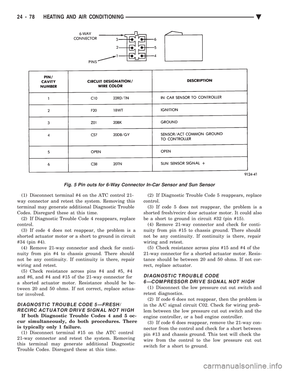
are shorted to battery voltage. For electrical pin numbers, refer to the wiring Pin
out charts (Figs. 1, 2, 3, 4, 5, or 6).
DIAGNOSTIC TROUBLE CODE 1ÐOUTPUT FAILURE WITH ALL OUTPUTS LOW
(1) Remove pin #2 from 21-way connector on control
and retest system. If code 01 does not appear, the
control is good. Disconnect 21-way connector from control. With an
ohmmeter, measure the resistance between pin #2 and
pin #12 of 21-way. This should be between 2,600 and
2,800 ohms. If yes, the power module is good. Source of voltage on pin #2 is in the wiring. Repair
and retest system. (2) Remove pin #13 from 21-way connector on con-
trol and retest system. If code 01 does not appear, the
control is good. Locate source of voltage on pin #13.
Repair and retest system. (3) Remove pin #5 from 21-way connector on control
and retest system. If code 01 does not appear, the
control is good. Locate source of voltage on pin #5.
Repair and retest system. (4) Remove pin #6 from 21-way connector on control
and retest system. If code 01 does not appear, the
control is good. Locate source of voltage on pin #6.
Repair and retest system. (5) Remove pin #15 from 21-way connector on con-
trol and retest system. If code 01 does not appear, the
control is good. Locate source of voltage on pin #15.
Repair and retest system.
DIAGNOSTIC TROUBLE CODE 2ÐBLEND AC- TUATOR DRIVE SIGNAL NOT HIGH
If both Diagnostic Trouble Codes 2 and 3 occur
simultaneously, do both procedures. There is
typically only 1 failure. (1) Disconnect terminal #6 on the ATC control 21-
way connector and retest the system. Note that remov-
ing this terminal may generate additional Diagnostic
Trouble Codes. Disregard these at this time. (2) If Diagnostic Trouble Code 2 reappears, replace
control. (3) If code 2 does not reappear, the problem is a
shorted blend door actuator motor or a short to ground
in circuit 33 (pin #6). (4) Remove 21-way connector and check for continu-
ity from pin #6 to chassis ground. There should not be
any continuity. If continuity is there, repair wiring and
retest. (5) Check resistance across pins #6 and #4 of the
21-way for a shorted actuator motor. Resistance should
be between 20 and 50 ohms. If not correct, replace
actuator.
DIAGNOSTIC TROUBLE CODE 3ÐMODE AC- TUATOR DRIVE SIGNAL NOT HIGH
If both Diagnostic Trouble Codes 2 and 3 occur
simultaneously, do both procedures. There is
typically only 1 failure. (1) Disconnect terminal #5 on the ATC control 21-
way connector and retest the system. Removing this
terminal may generate additional Diagnostic Trouble
Codes. Disregard these at this time. (2) If Diagnostic Trouble Code 3 reappears, replace
control. (3) If code 3 does not reappear, the problem is a
shorted mode door actuator motor, or a short to ground
in circuit #35 (pin #5). (4) Remove 21-way and check for continuity from pin
#5 to chassis ground. There should not be any continu-
ity. If continuity is there, repair wiring and retest.
24 - 74 HEATING AND AIR CONDITIONING Ä
Page 2381 of 2438
(5) Check resistance across pins #4 and #5 of the
21-way connector for a shorted actuator motor. Resis-
tance should be between 20 and 50 ohms. If not cor-
rect, replace actuator.DIAGNOSTIC TROUBLE CODE 4ÐACTUATOR DRIVE COMMON SIGNAL NOT HIGH
If both Diagnostic Trouble Codes 4 and 5 oc-
cur simultaneously, do both procedures. There
is typically only 1 failure.
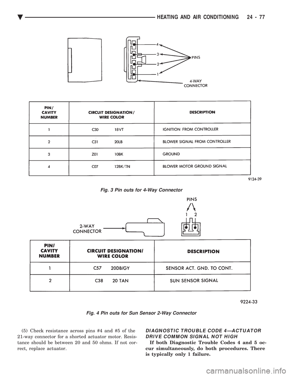
Fig. 3 Pin outs for 4-Way Connector
Fig. 4 Pin outs for Sun Sensor 2-Way Connector
Ä HEATING AND AIR CONDITIONING 24 - 77
Page 2382 of 2438
(1) Disconnect terminal #4 on the ATC control 21-
way connector and retest the system. Removing this
terminal may generate additional Diagnostic Trouble
Codes. Disregard these at this time. (2) If Diagnostic Trouble Code 4 reappears, replace
control. (3) If code 4 does not reappear, the problem is a
shorted actuator motor or a short to ground in circuit
#34 (pin #4). (4) Remove 21-way connector and check for conti-
nuity from pin #4 to chassis ground. There should
not be any continuity. If continuity is there, repair
wiring and retest. (5) Check resistance across pins #4 and #5, #4
and #6, and #4 and #15 of the 21-way connector for
a shorted actuator motor. Resistance should be be-
tween 20 and 50 ohms. If not correct, replace actua-
tor involved.
DIAGNOSTIC TROUBLE CODE 5ÐFRESH/ RECIRC ACTUATOR DRIVE SIGNAL NOT HIGH
If both Diagnostic Trouble Codes 4 and 5 oc-
cur simultaneously, do both procedures. There
is typically only 1 failure. (1) Disconnect terminal #15 on the ATC control
21-way connector and retest the system. Removing
this terminal may generate additional Diagnostic
Trouble Codes. Disregard these at this time. (2) If Diagnostic Trouble Code 5 reappears, replace
control. (3) If code 5 does not reappear, the problem is a
shorted fresh/recirc door actuator motor. It could also
be a short to ground in circuit #32 (pin #15). (4) Remove 21-way connector and check for conti-
nuity from pin #15 to chassis ground. There should
not be any continuity. If continuity is there, repair
wiring and retest. (5) Check resistance across pins #15 and #4 of the
21-way connector for a shorted actuator motor. Resis-
tance should be between 20 and 50 ohms. If not cor-
rect, replace actuator.
DIAGNOSTIC TROUBLE CODE 6ÐCOMPRESSOR DRIVE SIGNAL NOT HIGH
(1) Disconnect the low pressure cut out switch and
retest diagnostics. (2) If code 6 does not reappear, then the problem is
in the A/C signal circuit C02. Check for wiring prob-
lem between the low pressure cut out switch and the
engine controller, or a bad engine controller. (3) If code 6 does reappear, remove the 21-way con-
nector from the control and check for a short between
pin #13 and chassis ground. This test will check the
wire from the control to the low pressure cut out
switch for a short to ground.
Fig. 5 Pin outs for 6-Way Connector In-Car Sensor and Sun Sensor
24 - 78 HEATING AND AIR CONDITIONING Ä
Page 2384 of 2438
(4) If pin #13 shows continuity, repair circuit C02
and retest. (5) If no continuity is shown, replace the ATC con-
trol and retest.
DIAGNOSTIC TROUBLE CODE 7ÐBLOWER DRIVE SIGNAL NOT HIGH
First check the 4-way connector to the power
module for correct installation (1) With the ignition ON, check for ignition volt-
age to the power module pin #1 from the ATC con-
trol. If ignition is present at the power module,
proceed to step 3. If not proceed to step 2. (2) With the 21-way connector still connected and
the ignition ON, check for power module ignition
feed at the control pin #12. If ignition is not present,
replace the control. If ignition voltage is present, re-
pair the open in the wire between the control pin
#12 and power module pin #1. Retest system. (3) Turn ignition OFF and disconnect the 21-way
connector. Measure the resistance between pins #2
and #12. The resistance should read between 2,600
and 2,800 ohms. If correct, replace the ATC control.
If not correct, proceed to step 4. (4) Remove the 4-way connector from the power
module. Check for continuity between the ATC con-
trol pin #2 and power module pin #2. If no continu-
ity is shown, repair the wire for an open. If
continuity is shown, replace the power module and
retest.
DIAGNOSTIC TROUBLE CODE 8ÐA/D CONVERTOR INTERNAL FAILURE
Diagnostics will indicate a Diagnostic Trouble Code
8 if the internal reference voltage of the A/D Conver-
tor is not correct. This Diagnostic Trouble Code is
not serviceable. If a Diagnostic Trouble Code 8 oc-
curs, the computer control head must be replaced.
DIAGNOSTIC TROUBLE CODE 9ÐSUN LOAD SENSOR FAILURE
(1) Unplug the 21-way connector from the control
and check pin #19 for continuity to chassis ground.
If continuity is present, repair the wire shorted to
ground. If no continuity is present, proceed to step 2. (2) Plug the 21-way connector back in. Remove pin
#19 from the 21 way connector and run diagnostics
again. If Diagnostic Trouble Code 9 is still present,
replace the control. If code 9 is not present, replace
the sun sensor.
DIAGNOSTIC TROUBLE CODE 10ÐWATER TEMPERATURE SENSOR FAILURE
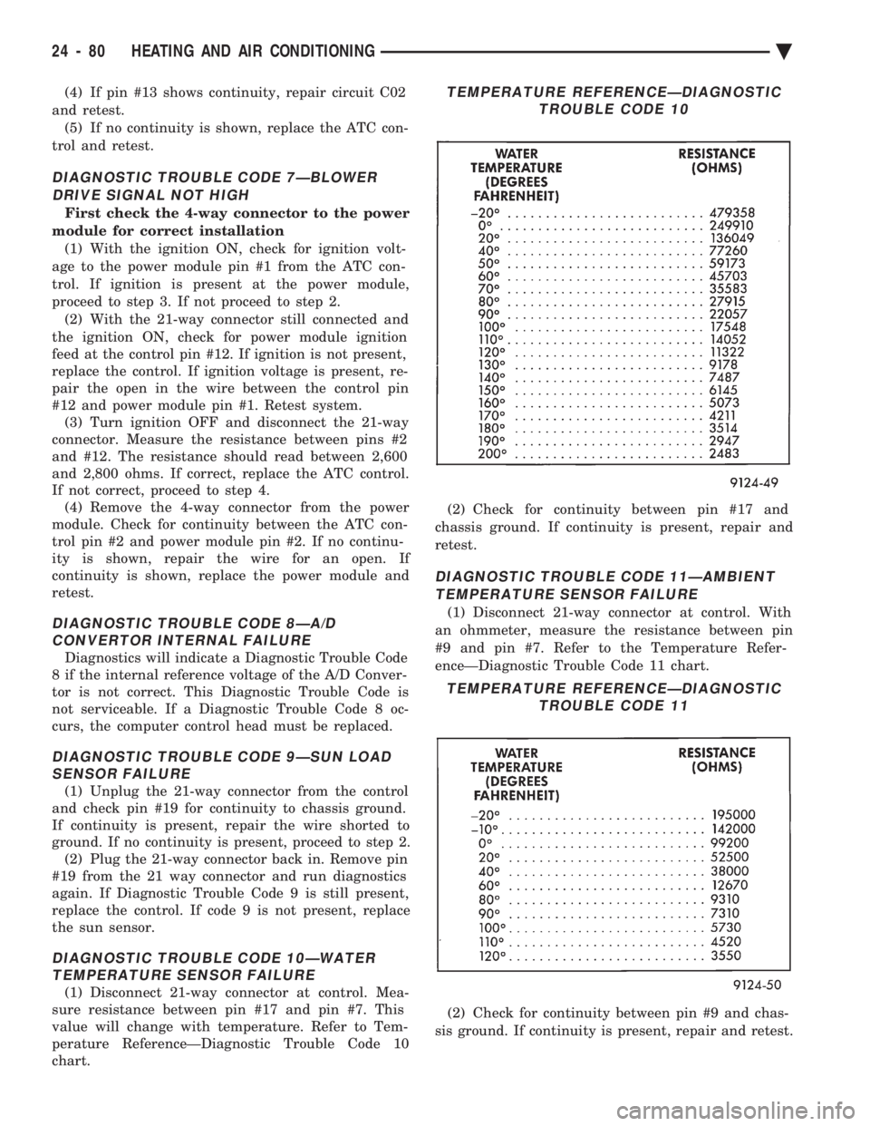
(1) Disconnect 21-way connector at control. Mea-
sure resistance between pin #17 and pin #7. This
value will change with temperature. Refer to Tem-
perature ReferenceÐDiagnostic Trouble Code 10
chart. (2) Check for continuity between pin #17 and
chassis ground. If continuity is present, repair and
retest.
DIAGNOSTIC TROUBLE CODE 11ÐAMBIENT TEMPERATURE SENSOR FAILURE
(1) Disconnect 21-way connector at control. With
an ohmmeter, measure the resistance between pin
#9 and pin #7. Refer to the Temperature Refer-
enceÐDiagnostic Trouble Code 11 chart.
(2) Check for continuity between pin #9 and chas-
sis ground. If continuity is present, repair and retest.
TEMPERATURE REFERENCEÐDIAGNOSTIC TROUBLE CODE 10
TEMPERATURE REFERENCEÐDIAGNOSTICTROUBLE CODE 11
24 - 80 HEATING AND AIR CONDITIONING Ä
Page 2385 of 2438
DIAGNOSTIC TROUBLE CODE 12ÐIN-CAR TEMPERATURE SENSOR/ASPIRATORFAILURE
(1) Disconnect 21-way connector at control. With
an ohmmeter, measure the resistance between pin
#20 and pin #7. Refer to Temperature Refer-
enceÐDiagnostic Trouble Code 11 chart for electrical
values. (2) Check for continuity between pin #20 and
chassis ground. If continuity is present, repair and
retest.
DIAGNOSTIC TROUBLE CODE 13ÐBLEND DOOR FAILED TO DRIVE TO HEAT POSITION
(1) Check door and linkage for binding.
(2) Disconnect 21-way connector from control head
and the 5-way connector from the blend air door ac-
tuator. Check continuity between pin #6 of the 21-
way connector and pin #5 of the 5-way connector. If
continuity is shown, go to step 3. If continuity is not
shown, repair circuit for an open circuit and retest
system. (3) Plug in the 5-way connector and check for re-
sistance between pins #4 and #6 of the 21-way con-
nector. A resistance of 20-50 ohms should be present.
If not, replace actuator. If correct, proceed to step 4. (4) If steps 1 and 2 indicate no failures, replace the
ATC control head.
DIAGNOSTIC TROUBLE CODE 14ÐBLEND DOOR FAILED TO DRIVE TO COLD POSITION
First check the 5-way connector to the blend
air door actuator for proper connection (1) Check door and linkage for binding.
(2) Remove the 21-way connector from the control.
With ignition ON, check for ignition voltage between
pin #8 of the 21-way connector and chassis ground.
If voltage is present, repair circuit for short to igni-
tion voltage. If voltage is not present, proceed to step
3. (3) Turn ignition OFF. With the 21-way still re-
moved, disconnect the 5-way connector from the
blend air door actuator. Check for continuity between
pin #8 of the 21-way connector and pin #1 of the
5-way connector. If continuity is not present, repair
open circuit. If present, continue to step 4. (4) Install the 5-way connector back into the blend
air door actuator and check for continuity between
the pins #7 and #8 of the 21-way connector. If con-
tinuity is present, replace the ATC control. If conti-
nuity is not present, replace the blend air door
actuator.
DIAGNOSTIC TROUBLE CODE 15ÐBLEND DOOR FEEDBACK SHORTED TO GROUND
(1) Remove the 21-way connector from the control
and the 5-way connector from the blend air door ac-
tuator. (2) Check for continuity between pin #8 of the 21-
way connector and chassis ground. If present, repair
circuit for short to ground. If not present, continue to
step 3. (3) Plug in the 5-way connector and measure resis-
tance between pins #7 and #8 of the 21-way connec-
tor. If the resistance is less than 10 ohms, replace the
actuator. If not, replace the control head.
DIAGNOSTIC TROUBLE CODE 16ÐMODE DOOR MOVED DURING BLEND DOOR TEST
(1) Remove the 21-way connector from the control
and the 5-way connector from the three actuators. (2) Check for continuity between pin #4 of the 21-
way connector and pin #4 of each actuator. If conti-
nuity is not present for a particular actuator circuit,
repair that circuit and retest system. If continuity is
present for all circuits, continue to step 3. (3) Plug in the 5-way connectors and check for re-
sistance between pins #4 and #6 of the 21-way con-
nector for the blend air actuator. Then check pins #4
and #5 of the 21-way for the mode actuator. The re-
sistance should be between 20-50 ohms. If either of
the actuators do not pass the resistance tests, replace
that particular actuator and retest the system. If
both pass the resistance test, replace the ATC con-
trol.
DIAGNOSTIC TROUBLE CODE 17ÐMODE DOOR FAILED TO DRIVE TO DEFROST
(1) Disconnect 21-way connector from control head
and the 5-way connector from the blend air door ac-
tuator. Check continuity between pin #5 of the 21-
way connector and pin #5 of the 5-way connector. If
continuity is present, proceed to step 2. If continuity
is not present, repair open circuit and retest system. (2) Plug in the 5-way connector and check for re-
sistance between pins #4 and #5 of the 21-way con-
nector. A resistance of 20-50 ohms should be present.
If not, replace actuator. If correct, proceed to step 3. (3) If steps 1 and 2 do not indicate any failures, re-
place the ATC control head.
DIAGNOSTIC TROUBLE CODE 18ÐMODE DOOR FAILED TO DRIVE TO PANEL
Check the 5-way connector to the mode door
actuator for proper installation. (1) Check the door and linkage for binding.
(2) Remove the 21-way connector from the control.
With ignition ON, check for ignition voltage between
pin #16 of the 21-way connector and chassis ground.
If voltage is present, repair circuit for short to igni-
tion voltage. If voltage is not present, proceed to step
3. (3) Turn ignition OFF. With the 21-way connector
still removed, disconnect the 5-way connector from
the mode door actuator. Check for continuity be-
tween pin #16 of the 21-way connector, and pin #1
Ä HEATING AND AIR CONDITIONING 24 - 81
Page 2386 of 2438
of the 5-way connector. If continuity is not present,
repair circuit for an open. If present, continue to step
4.(4) Install 5-way connector back into the mode
door actuator. Then check for continuity between
pins #7 and #16 of the 21-way connector. If continu-
ity is present, replace the ATC control. If continuity
is not present, replace the mode door actuator.
DIAGNOSTIC TROUBLE CODE 19ÐMODE DOOR FEEDBACK SHORTED TO GROUND
(1) Remove the 21-way connector from the control,
and the 5 way connector from the mode door actua-
tor. (2) Check for continuity between pin #16 of the
21-way connector and chassis ground. If present, re-
pair circuit for short to ground. If not present, con-
tinue to step 3. (3) Plug in the 5-way connector and measure resis-
tance between pins #7 and #16 of the 21-way con-
nector. If the resistance is less than 10 ohms, replace
the actuator. If not, replace the control head.
DIAGNOSTIC TROUBLE CODE 20ÐBLEND DOOR MOVED DURING MODE DOOR TEST
(1) Remove the 21-way connector from the control
and the 5-way connector from the three actuators. (2) Check for continuity between pin #4 of the 21-
way connector and pin #4 of each actuator. If conti-
nuity is not present for a particular actuator circuit,
repair that circuit and retest system. If continuity is
present for all circuits, continue to step 3. (3) Plug in the 5-way connectors and check for re-
sistance between pins #4 and #6 of the 21-way con-
nector for the blend air actuator. Then check pins #4
and #5 of the 21-way connector for the mode actua-
tor. The resistance should be between 20-50 ohms. If
either of the actuators do not pass the resistance
tests, replace that particular actuator and retest the
system. If both pass the resistance test, replace the
ATC control.
DIAGNOSTIC TROUBLE CODE 21ÐROM CHECK SUM ERROR
During the Diagnostics test, the computer will ver-
ify it's own internal program. If it finds any part to
be bad, a Diagnostic Trouble Code 21 will be set.
This Diagnostic Trouble Code is not serviceable. If a
Fail Code 21 occurs, the ATC Control Module must
be replaced.
DIAGNOSTIC TROUBLE CODE 22ÐCOMPUTER ERROR
If incorrect data is found in the ATC Control com-
puter module, a Diagnostic Trouble Code 22 will be
set. This Fail Code is not serviceable. If a Diagnostic
Trouble Code 22 occurs, the ATC Control Module
must be replaced.
DIAGNOSTIC TROUBLE CODE 23ÐBLEND
DOOR FEEDBACK FAILED
This Diagnostic Trouble Code is set during normal
ATC operation. The Diagnostic Trouble Code will be
set only after the ATC control has been operating for
15 minutes. The control will compensate for the feed-
back failure immediately upon power up, but the Di-
agnostic Trouble Code will not be set until the time
limit has been met. Diagnostic Trouble Code 23 will be stored within
the ATC Control, and must be cleared after the fail-
ure has been repaired. To clear this Diagnostic Trou-
ble Code, refer to Erasing Diagnostic Trouble Codes
23 through 28 from ATC Control. Follow service procedures for Diagnostic Trouble
Codes 14 and 15 when repairing.
DIAGNOSTIC TROUBLE CODE 24ÐMODE DOOR FEEDBACK FAILED
This Diagnostic Trouble Code is set during normal
ATC operation. The Diagnostic Trouble Code will be
set only after the ATC control has been operating for
15 minutes. The control will compensate for the feed-
back failure immediately upon power up, but the Di-
agnostic Trouble Code will not be set until the time
limit has been met. Diagnostic Trouble Code 24 will be stored within
the ATC Control, and must be cleared after the fail-
ure has been repaired. To clear this Diagnostic Trou-
ble Code, refer to Erasing Diagnostic Trouble Codes
23 through 28 From ATC Control. Follow service procedures for Diagnostic Trouble
Codes 18 and 19 when repairing.
DIAGNOSTIC TROUBLE CODE 25ÐAMBIENT TEMPERATURE SENSOR FAILURE
This Diagnostic Trouble Code is set during normal
ATC operation. The Diagnostic Trouble Code will be
set only after the ATC control has been operating for
15 minutes. The control will compensate for the feed-
back failure immediately upon power up, but the Di-
agnostic Trouble Code will not be set until the time
limit has been met. Diagnostic Trouble Code 25 will be stored within
the ATC Control, and must be cleared after the fail-
ure has been repaired. To clear this Diagnostic Trou-
ble Code, refer to Erasing Diagnostic Trouble Codes
23 through 28 from ATC Control. Follow service procedures for Diagnostic Trouble
Code 11 when repairing.
DIAGNOSTIC TROUBLE CODE 26ÐIN-CAR TEMPERATURE SENSOR/ASPIRATOR FAILED
This Diagnostic Trouble Code is set during normal
ATC operation. The Diagnostic Trouble Code will be
set only after the ATC control has been operating for
15 minutes. The control will compensate for the feed-
24 - 82 HEATING AND AIR CONDITIONING Ä
Page 2387 of 2438
back failure immediately upon power up, but the Di-
agnostic Trouble Code will not be set until the time
limit has been met. Diagnostic Trouble Code 26 will be stored within
the ATC Control, and must be cleared after the fail-
ure has been repaired. To clear this Diagnostic Trou-
ble Code, refer to Erasing Diagnostic Trouble Codes
23 through 28 from ATC Control. Follow service procedures for Diagnostic Trouble
Code 12 when repairing.
DIAGNOSTIC TROUBLE CODE 27ÐSUN LOAD SENSOR FAILED
This Diagnostic Trouble Code is set during normal
ATC operation. The Diagnostic Trouble Code will be
set only after the ATC control has been operating for
15 minutes. The control will compensate for the feed-
back failure immediately upon power up, but the Di-
agnostic Trouble Code will not be set until the time
limit has been met. Diagnostic Trouble Code 27 will be stored within
the ATC Control, and must be cleared after the fail-
ure has been repaired. To clear this Diagnostic Trou-
ble Code, refer to Erasing Diagnostic Trouble Codes
23 through 28 from ATC Control. Follow service procedures for Diagnostic Trouble
Code 12 when repairing.
DIAGNOSTIC TROUBLE CODE 28ÐWATER TEMPERATURE SENSOR FAILED
This Diagnostic Trouble Code is set during normal
ATC operation. The Diagnostic Trouble Code will be
set only after the ATC control has been operating for
15 minutes. The control will compensate for the feed-
back failure immediately upon power up, but the Di-
agnostic Trouble Code will not be set until the time
limit has been met. Diagnostic Trouble Code 28 will be stored within
the ATC Control and must be cleared after the fail- ure has been repaired. To clear this Diagnostic Trou-
ble Code, refer to Erasing Diagnostic Trouble Codes
23 through 28 from ATC Control. Follow service procedures for Diagnostic Trouble
Code 10 when repairing.
ERASING DIAGNOSTIC TROUBLE CODES
Diagnostic Trouble Codes 23 through 28 are stored
within the ATC in the computer memory. These
codes may be erased from the memory after the cor-
rect repairs have been made. Intermittent Diagnostic
Trouble Codes 23 through 28 will be stored until
they are erased. (1) Run the DIAGNOSTIC TEST.
(2) Depress the PANEL button to access all Diag-
nostic Trouble Codes. When the Display begins flash-
ing alternating zeros, you can do three things:
² Do nothing, and in five seconds control will return
to normal ATC operation. All codes will remain
stored in the control.
² Depress any button within five seconds, other than
A/C, and stop the test immediately. Control will re-
turn to normal ATC operation.
² Depress the A/C button within five seconds, and
proceed to the erasing procedure. By depressing the
A/C button, you will not erase any Diagnostic Trou-
ble Codes. You will only access the next part of the
procedure. Proceed to step 3. (3) After you depress the A/C button the display
will alternate E's. This is for ERASE. You can now
do two things:
² Do nothing, and in five seconds, all Diagnostic
Trouble Codes from 23 through 28 will be erased
from the ATC control.
² Depress any button within five seconds, and Diag-
nostic Trouble Codes will not be erased. Control will return to normal ATC operation.
Ä HEATING AND AIR CONDITIONING 24 - 83
Page 2405 of 2438
EXHAUST EMISSION CONTROLS INDEX
page page
Air Aspiration System ..................... 24
EGR Gas Flow Test ...................... 21
EGR System On-Board Diagnostics ........... 21
EGR Tube ServiceÐ2.2L and 2.5L TBI Engines . 22
EGR Tube ServiceÐ3.0L Engines ............ 22
EGR Tube ServiceÐ3.3L and 3.8L Engines .... 22
EGR Valve ServiceÐ2.2L and 2.5L TBI Engines . 22 EGR Valve ServiceÐ3.0L Engines
........... 22
EGR Valve ServiceÐ3.3L and 3.8L Engines .... 22
Exhaust Gas Recirculation (EGR) System ...... 20
Exhaust Gas Recirculation (EGR) System Test . . 21
Heated Inlet Air System ................... 17
Heated Oxygen Sensor (O
2Sensor) .......... 18
HEATED INLET AIR SYSTEM
2.5L MPI (Flexible Fuel AA-body), Turbo III, 3.0L,
3.3L and 3.8L engines do not use a heated inlet air
system. 2.2L and 2.5L TBI air cleaners have a heated air
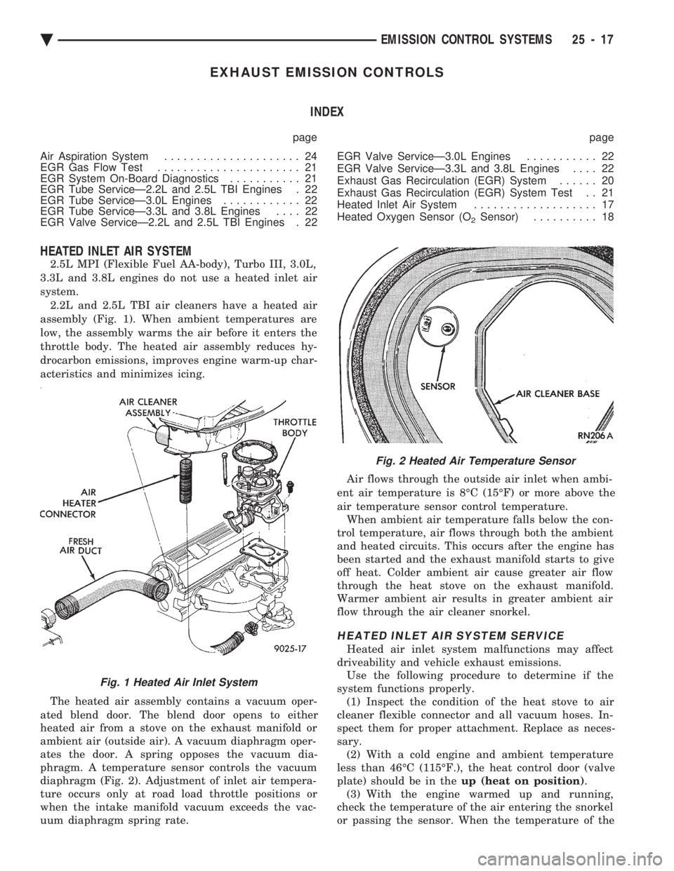
assembly (Fig. 1). When ambient temperatures are
low, the assembly warms the air before it enters the
throttle body. The heated air assembly reduces hy-
drocarbon emissions, improves engine warm-up char-
acteristics and minimizes icing.
The heated air assembly contains a vacuum oper-
ated blend door. The blend door opens to either
heated air from a stove on the exhaust manifold or
ambient air (outside air). A vacuum diaphragm oper-
ates the door. A spring opposes the vacuum dia-
phragm. A temperature sensor controls the vacuum
diaphragm (Fig. 2). Adjustment of inlet air tempera-
ture occurs only at road load throttle positions or
when the intake manifold vacuum exceeds the vac-
uum diaphragm spring rate. Air flows through the outside air inlet when ambi-
ent air temperature is 8ÉC (15ÉF) or more above the
air temperature sensor control temperature. When ambient air temperature falls below the con-
trol temperature, air flows through both the ambient
and heated circuits. This occurs after the engine has
been started and the exhaust manifold starts to give
off heat. Colder ambient air cause greater air flow
through the heat stove on the exhaust manifold.
Warmer ambient air results in greater ambient air
flow through the air cleaner snorkel.
HEATED INLET AIR SYSTEM SERVICE
Heated air inlet system malfunctions may affect
driveability and vehicle exhaust emissions. Use the following procedure to determine if the
system functions properly. (1) Inspect the condition of the heat stove to air
cleaner flexible connector and all vacuum hoses. In-
spect them for proper attachment. Replace as neces-
sary. (2) With a cold engine and ambient temperature
less than 46ÉC (115ÉF.), the heat control door (valve
plate) should be in the up (heat on position).
(3) With the engine warmed up and running,
check the temperature of the air entering the snorkel
or passing the sensor. When the temperature of the
Fig. 1 Heated Air Inlet System
Fig. 2 Heated Air Temperature Sensor
Ä EMISSION CONTROL SYSTEMS 25 - 17