check oil CHEVROLET PLYMOUTH ACCLAIM 1993 Owner's Guide
[x] Cancel search | Manufacturer: CHEVROLET, Model Year: 1993, Model line: PLYMOUTH ACCLAIM, Model: CHEVROLET PLYMOUTH ACCLAIM 1993Pages: 2438, PDF Size: 74.98 MB
Page 448 of 2438

ing, detonation and cooling system malfunctions also
can cause spark plug overheating.
SPARK PLUG SERVICE
When replacing the spark plug and coil cables,
route the cables correctly and secure them in the ap-
propriate retainers. Failure to route the cables prop-
erly can cause the radio to reproduce ignition noise,
cross ignition of the spark plugs or short circuit the
cables to ground.
SPARK PLUG REMOVAL
Always remove the spark plug cable by grasping at
the spark plug boot turning, the boot 1/2 turn and
pulling straight back in a steady motion. (1) Prior to removing the spark plug spray com-
pressed air around the spark plug hole and the area
around the spark plug. (2) Remove the spark plug using a quality socket
with a rubber or foam insert. (3) Inspect the spark plug condition. Refer to
Spark Plug Condition in this section.
SPARK PLUG GAP ADJUSTMENT Check the spark plug gap with a gap gauge. If the
gap is not correct, adjust it by bending the ground
electrode (Fig. 6).
SPARK PLUG INSTALLATION (1) To avoid cross threading, start the spark plug
into the cylinder head by hand. (2) Tighten spark plugs to 28 N Im (20 ft. lbs.)
torque. (3) Install spark plug cables over spark plugs.
POWERTRAIN CONTROL MODULE (PCM)
The ignition system is regulated by the powertrain
control module (PCM) (Fig. 14). The PCM supplies
battery voltage to the ignition coil through the Auto
Shutdown (ASD) Relay. The PCM also controls the
ground circuit for the ignition coil. By switching the ground path for the coil on and off, the PCM adjusts
ignition timing to meet changing engine operating
conditions.
During the crank-start period the PCM advances
ignition timing a set amount. During engine opera-
tion, the amount of spark advance provided by the
PCM is determined by these input factors:
² coolant temperature
² engine RPM
² available manifold vacuum
The PCM also regulates the fuel injection system.
Refer to the Fuel Injection sections of Group 14.
DISTRIBUTOR PICK-UPÐPCM INPUT
The engine speed input is supplied to the power-
train control module (PCM) by the distributor pick-
up. The distributor pick-up is a Hall Effect device
(Fig. 15 or Fig. 16).
A shutter (sometimes referred to as an interrupter)
is attached to the distributor shaft. The shutter con-
tains four blades, one per engine cylinder. A switch
plate is mounted to the distributor housing above the
shutter. The switch plate contains the distributor
Fig. 14 Powertrain control module (PCM)
Fig. 15 DistributorÐ2.2L and 2.5L TBI Engines
Fig. 13 Spark Plug Overheating
8D - 6 IGNITION SYSTEMS Ä
Page 454 of 2438
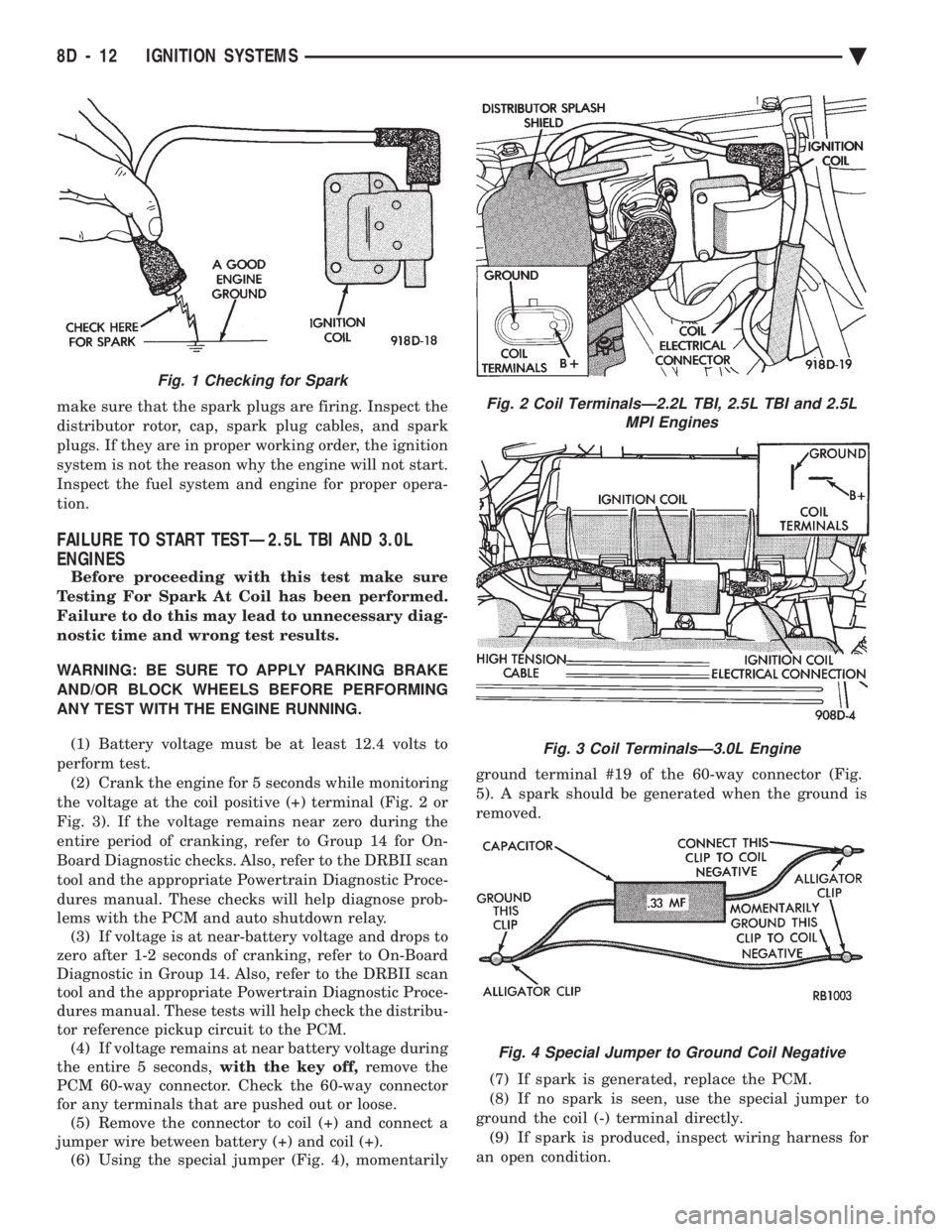
make sure that the spark plugs are firing. Inspect the
distributor rotor, cap, spark plug cables, and spark
plugs. If they are in proper working order, the ignition
system is not the reason why the engine will not start.
Inspect the fuel system and engine for proper opera-
tion.
FAILURE TO START TESTÐ2.5L TBI AND 3.0L
ENGINES
Before proceeding with this test make sure
Testing For Spark At Coil has been performed.
Failure to do this may lead to unnecessary diag-
nostic time and wrong test results.
WARNING: BE SURE TO APPLY PARKING BRAKE
AND/OR BLOCK WHEELS BEFORE PERFORMING
ANY TEST WITH THE ENGINE RUNNING.
(1) Battery voltage must be at least 12.4 volts to
perform test. (2) Crank the engine for 5 seconds while monitoring
the voltage at the coil positive (+) terminal (Fig. 2 or
Fig. 3). If the voltage remains near zero during the
entire period of cranking, refer to Group 14 for On-
Board Diagnostic checks. Also, refer to the DRBII scan
tool and the appropriate Powertrain Diagnostic Proce-
dures manual. These checks will help diagnose prob-
lems with the PCM and auto shutdown relay. (3) If voltage is at near-battery voltage and drops to
zero after 1-2 seconds of cranking, refer to On-Board
Diagnostic in Group 14. Also, refer to the DRBII scan
tool and the appropriate Powertrain Diagnostic Proce-
dures manual. These tests will help check the distribu-
tor reference pickup circuit to the PCM. (4) If voltage remains at near battery voltage during
the entire 5 seconds, with the key off,remove the
PCM 60-way connector. Check the 60-way connector
for any terminals that are pushed out or loose. (5) Remove the connector to coil (+) and connect a
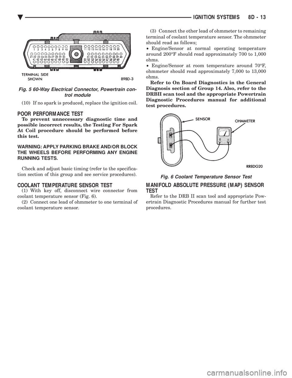
jumper wire between battery (+) and coil (+). (6) Using the special jumper (Fig. 4), momentarily ground terminal #19 of the 60-way connector (Fig.
5). A spark should be generated when the ground is
removed.
(7) If spark is generated, replace the PCM.
(8) If no spark is seen, use the special jumper to
ground the coil (-) terminal directly. (9) If spark is produced, inspect wiring harness for
an open condition.
Fig. 2 Coil TerminalsÐ2.2L TBI, 2.5L TBI and 2.5L MPI Engines
Fig. 3 Coil TerminalsÐ3.0L Engine
Fig. 4 Special Jumper to Ground Coil Negative
Fig. 1 Checking for Spark
8D - 12 IGNITION SYSTEMS Ä
Page 455 of 2438
(10) If no spark is produced, replace the ignition coil.
POOR PERFORMANCE TEST
To prevent unnecessary diagnostic time and
possible incorrect results, the Testing For Spark
At Coil procedure should be performed before
this test.
WARNING: APPLY PARKING BRAKE AND/OR BLOCK
THE WHEELS BEFORE PERFORMING ANY ENGINE
RUNNING TESTS.
Check and adjust basic timing (refer to the specifica-
tion section of this group and see service procedures).
COOLANT TEMPERATURE SENSOR TEST
(1) With key off, disconnect wire connector from
coolant temperature sensor (Fig. 6). (2) Connect one lead of ohmmeter to one terminal of
coolant temperature sensor. (3) Connect the other lead of ohmmeter to remaining
terminal of coolant temperature sensor. The ohmmeter
should read as follows;
² Engine/Sensor at normal operating temperature
around 200ÉF should read approximately 700 to 1,000
ohms.
² Engine/Sensor at room temperature around 70ÉF,
ohmmeter should read approximately 7,000 to 13,000
ohms. Refer to On Board Diagnostics in the General
Diagnosis section of Group 14. Also, refer to the
DRBII scan tool and the appropriate Powertrain
Diagnostic Procedures manual for additional
test procedures.
MANIFOLD ABSOLUTE PRESSURE (MAP) SENSOR
TEST
Refer to the DRB II scan tool and appropriate Pow-
ertrain Diagnostic Procedures manual for further test
procedures.
Fig. 5 60-Way Electrical Connector, Powertrain con- trol module
Fig. 6 Coolant Temperature Sensor Test
Ä IGNITION SYSTEMS 8D - 13
Page 468 of 2438
tance. The cables provide suppression of radio fre-
quency emissions from the ignition system.Check the spark plug cable connections for good
contact at the coil and distributor cap towers and at
the spark plugs. Terminals should be fully seated.
The nipples and spark plug covers should be in good
condition. Nipples should fit tightly on the coil and
distributor cap towers and spark plug cover should
fit tight around spark plug insulators. Loose cable
connections can cause ignition malfunctions by per-
mitting water to enter the towers, corroding, and in-
creasing resistance.
SPARK PLUGS
The 2.2L Turbo III, 3.3L and 3.8L engines use re-
sistor spark plugs. They have resistance values of
6,000 to 20,000 ohms when checked with at least a
1000 volt tester. Remove the spark plugs and examine them for
burned electrodes and fouled, cracked or broken por-
celain insulators. Keep plugs arranged in the order
in which they were removed from the engine. An iso-
lated plug displaying an abnormal condition indi-
cates that a problem exists in the corresponding
cylinder. Replace spark plugs at the intervals recom-
mended in Group O. Spark plugs that have low milage may be cleaned
and reused if not otherwise defective. Refer to the
Spark Plug Condition section of this group. After
cleaning, file the center electrode flat with a small
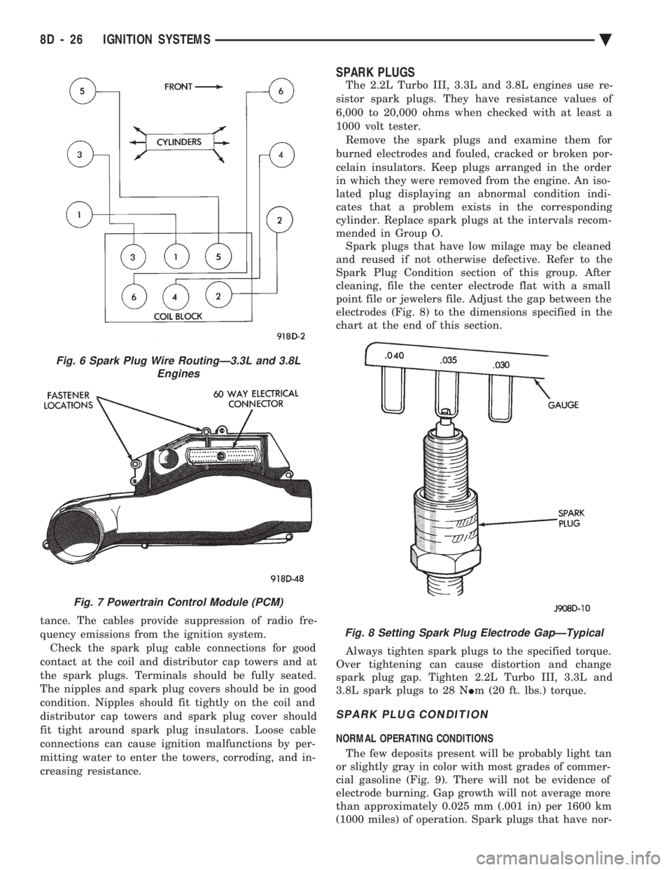
point file or jewelers file. Adjust the gap between the
electrodes (Fig. 8) to the dimensions specified in the
chart at the end of this section.
Always tighten spark plugs to the specified torque.
Over tightening can cause distortion and change
spark plug gap. Tighten 2.2L Turbo III, 3.3L and
3.8L spark plugs to 28 N Im (20 ft. lbs.) torque.
SPARK PLUG CONDITION
NORMAL OPERATING CONDITIONS
The few deposits present will be probably light tan
or slightly gray in color with most grades of commer-
cial gasoline (Fig. 9). There will not be evidence of
electrode burning. Gap growth will not average more
than approximately 0.025 mm (.001 in) per 1600 km
(1000 miles) of operation. Spark plugs that have nor-
Fig. 6 Spark Plug Wire RoutingÐ3.3L and 3.8L Engines
Fig. 7 Powertrain Control Module (PCM)
Fig. 8 Setting Spark Plug Electrode GapÐTypical
8D - 26 IGNITION SYSTEMS Ä
Page 477 of 2438
2.2L TURBO III, 3.3L AND 3.8L IGNITION SYSTEMÐDIAGNOSTIC PROCEDURES INDEX
page page
Check Coil TestÐ3.3L and 3.8L Engines ...... 36
Check Coil TestÐTurbo III Engine ........... 35
Coolant Temperature Sensor Test ............ 38
Crankshaft Position Sensor and Camshaft Position Sensor Tests .......................... 38 Failure to Start Test
...................... 37
Failure to Start TestÐTurbo III Engine ........ 36
Manifold Absolute Pressure (MAP) Sensor Test . 38
Testing for Spark at CoilÐ3.3L and 3.8L Engines . 36
Testing for Spark at CoilÐTurbo III Engine ..... 35
TESTING FOR SPARK AT COILÐTURBO III ENGINE
WARNING: THE DIRECT IGNITION SYSTEM GENER-
ATES APPROXIMATELY 40,000 VOLTS. PERSONAL
INJURY COULD RESULT FROM CONTACT WITH
THIS SYSTEM.
The coil pack contains 2 independent coils. Each
coil must be checked individually.
CAUTION: Spark plug wire damage may occur if the
spark plug is moved more than 1/4 inch away from
the engine ground.
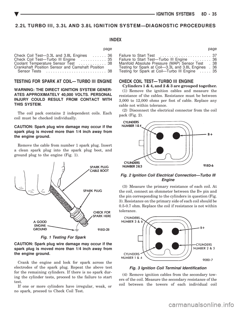
Remove the cable from number 1 spark plug. Insert
a clean spark plug into the spark plug boot, and
ground plug to the engine (Fig. 1).
CAUTION: Spark plug wire damage may occur if the
spark plug is moved more than 1/4 inch away from
the engine ground. Crank the engine and look for spark across the
electrodes of the spark plug. Repeat the above test
for the remaining cylinders. If there is no spark dur-
ing the cylinder tests, proceed to the failure to start
test. If one or more cylinders have irregular, weak, or
no spark, proceed to Check Coil Test.
CHECK COIL TESTÐTURBO III ENGINE
Cylinder s1&4,and2&3are grouped together.
(1) Remove the ignition cables and measure the
resistance of the cables. Resistance must be between
3,000 to 12,000 ohms per foot of cable. Replace any
cable not within tolerance. (2) Disconnect the electrical connector from the coil
pack (Fig. 2).
(3) Measure the primary resistance of each coil. At
the coil, connect an ohmmeter between the B+ pin and
the pin corresponding to the cylinders in question (Fig.
3). Resistance on the primary side of each coil should be
0.5-0.7 ohm. Replace the coil if resistance is not within
tolerance.
(4) Remove ignition cables from the secondary tow-
ers of the coil. Measure the secondary resistance of the
coil between the towers of each individual coil
Fig. 1 Testing For Spark
Fig. 2 Ignition Coil Electrical ConnectionÐTurbo III Engine
Fig. 3 Ignition Coil Terminal Identification
Ä IGNITION SYSTEMS 8D - 35
Page 478 of 2438
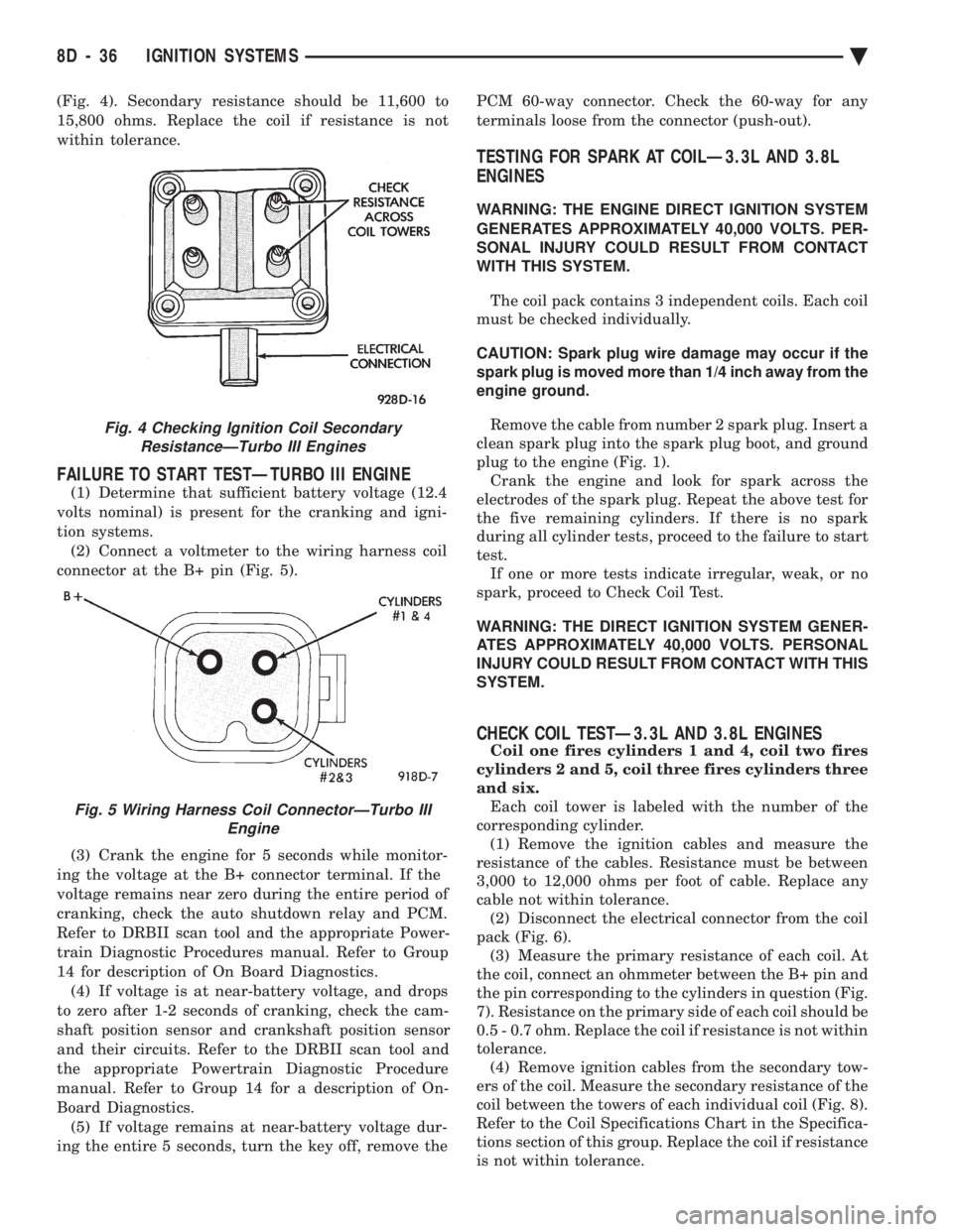
(Fig. 4). Secondary resistance should be 11,600 to
15,800 ohms. Replace the coil if resistance is not
within tolerance.
FAILURE TO START TESTÐTURBO III ENGINE
(1) Determine that sufficient battery voltage (12.4
volts nominal) is present for the cranking and igni-
tion systems. (2) Connect a voltmeter to the wiring harness coil
connector at the B+ pin (Fig. 5).
(3) Crank the engine for 5 seconds while monitor-
ing the voltage at the B+ connector terminal. If the
voltage remains near zero during the entire period of
cranking, check the auto shutdown relay and PCM.
Refer to DRBII scan tool and the appropriate Power-
train Diagnostic Procedures manual. Refer to Group
14 for description of On Board Diagnostics. (4) If voltage is at near-battery voltage, and drops
to zero after 1-2 seconds of cranking, check the cam-
shaft position sensor and crankshaft position sensor
and their circuits. Refer to the DRBII scan tool and
the appropriate Powertrain Diagnostic Procedure
manual. Refer to Group 14 for a description of On-
Board Diagnostics. (5) If voltage remains at near-battery voltage dur-
ing the entire 5 seconds, turn the key off, remove the PCM 60-way connector. Check the 60-way for any
terminals loose from the connector (push-out).
TESTING FOR SPARK AT COILÐ3.3L AND 3.8L
ENGINES
WARNING: THE ENGINE DIRECT IGNITION SYSTEM
GENERATES APPROXIMATELY 40,000 VOLTS. PER-
SONAL INJURY COULD RESULT FROM CONTACT
WITH THIS SYSTEM.
The coil pack contains 3 independent coils. Each coil
must be checked individually.
CAUTION: Spark plug wire damage may occur if the
spark plug is moved more than 1/4 inch away from the
engine ground.
Remove the cable from number 2 spark plug. Insert a
clean spark plug into the spark plug boot, and ground
plug to the engine (Fig. 1). Crank the engine and look for spark across the
electrodes of the spark plug. Repeat the above test for
the five remaining cylinders. If there is no spark
during all cylinder tests, proceed to the failure to start
test. If one or more tests indicate irregular, weak, or no
spark, proceed to Check Coil Test.
WARNING: THE DIRECT IGNITION SYSTEM GENER-
ATES APPROXIMATELY 40,000 VOLTS. PERSONAL
INJURY COULD RESULT FROM CONTACT WITH THIS
SYSTEM.
CHECK COIL TESTÐ3.3L AND 3.8L ENGINES
Coil one fires cylinders 1 and 4, coil two fires
cylinders 2 and 5, coil three fires cylinders three
and six. Each coil tower is labeled with the number of the
corresponding cylinder. (1) Remove the ignition cables and measure the
resistance of the cables. Resistance must be between
3,000 to 12,000 ohms per foot of cable. Replace any
cable not within tolerance. (2) Disconnect the electrical connector from the coil
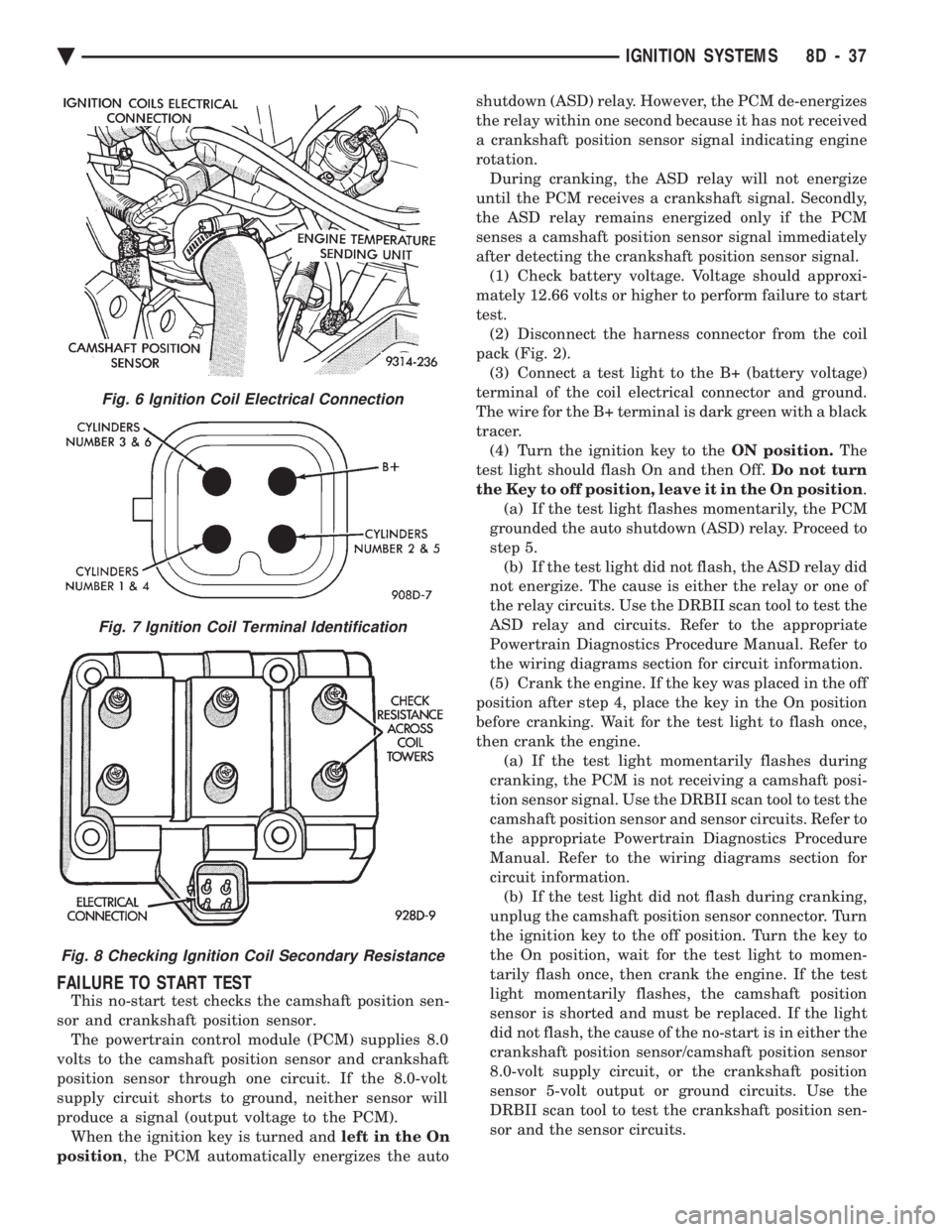
pack (Fig. 6). (3) Measure the primary resistance of each coil. At
the coil, connect an ohmmeter between the B+ pin and
the pin corresponding to the cylinders in question (Fig.
7). Resistance on the primary side of each coil should be
0.5 - 0.7 ohm. Replace the coil if resistance is not within
tolerance. (4) Remove ignition cables from the secondary tow-
ers of the coil. Measure the secondary resistance of the
coil between the towers of each individual coil (Fig. 8).
Refer to the Coil Specifications Chart in the Specifica-
tions section of this group. Replace the coil if resistance
is not within tolerance.
Fig. 4 Checking Ignition Coil Secondary ResistanceÐTurbo III Engines
Fig. 5 Wiring Harness Coil ConnectorÐTurbo III Engine
8D - 36 IGNITION SYSTEMS Ä
Page 479 of 2438
FAILURE TO START TEST
This no-start test checks the camshaft position sen-
sor and crankshaft position sensor. The powertrain control module (PCM) supplies 8.0
volts to the camshaft position sensor and crankshaft
position sensor through one circuit. If the 8.0-volt
supply circuit shorts to ground, neither sensor will
produce a signal (output voltage to the PCM). When the ignition key is turned and left in the On
position , the PCM automatically energizes the auto shutdown (ASD) relay. However, the PCM de-energizes
the relay within one second because it has not received
a crankshaft position sensor signal indicating engine
rotation.
During cranking, the ASD relay will not energize
until the PCM receives a crankshaft signal. Secondly,
the ASD relay remains energized only if the PCM
senses a camshaft position sensor signal immediately
after detecting the crankshaft position sensor signal. (1) Check battery voltage. Voltage should approxi-
mately 12.66 volts or higher to perform failure to start
test. (2) Disconnect the harness connector from the coil
pack (Fig. 2). (3) Connect a test light to the B+ (battery voltage)
terminal of the coil electrical connector and ground.
The wire for the B+ terminal is dark green with a black
tracer. (4) Turn the ignition key to the ON position.The
test light should flash On and then Off. Do not turn
the Key to off position, leave it in the On position .
(a) If the test light flashes momentarily, the PCM
grounded the auto shutdown (ASD) relay. Proceed to
step 5. (b) If the test light did not flash, the ASD relay did
not energize. The cause is either the relay or one of
the relay circuits. Use the DRBII scan tool to test the
ASD relay and circuits. Refer to the appropriate
Powertrain Diagnostics Procedure Manual. Refer to
the wiring diagrams section for circuit information.
(5) Crank the engine. If the key was placed in the off
position after step 4, place the key in the On position
before cranking. Wait for the test light to flash once,
then crank the engine. (a) If the test light momentarily flashes during
cranking, the PCM is not receiving a camshaft posi-
tion sensor signal. Use the DRBII scan tool to test the
camshaft position sensor and sensor circuits. Refer to
the appropriate Powertrain Diagnostics Procedure
Manual. Refer to the wiring diagrams section for
circuit information. (b) If the test light did not flash during cranking,
unplug the camshaft position sensor connector. Turn
the ignition key to the off position. Turn the key to
the On position, wait for the test light to momen-
tarily flash once, then crank the engine. If the test
light momentarily flashes, the camshaft position
sensor is shorted and must be replaced. If the light
did not flash, the cause of the no-start is in either the
crankshaft position sensor/camshaft position sensor
8.0-volt supply circuit, or the crankshaft position
sensor 5-volt output or ground circuits. Use the
DRBII scan tool to test the crankshaft position sen-
sor and the sensor circuits.
Fig. 6 Ignition Coil Electrical Connection
Fig. 7 Ignition Coil Terminal Identification
Fig. 8 Checking Ignition Coil Secondary Resistance
Ä IGNITION SYSTEMS 8D - 37
Page 482 of 2438

(5) Disconnect electrical connector from coolant
temperature sensor. (6) Remove sensor from engine.
INSTALLATION
(1) Tighten the coolant sensor to 7 N Im (60 in. lbs.)
torque. (2) Connect electrical connector to sensor.
(3) Fill cooling system. Refer to Group 7, Cooling
System. (4) Install coil. Tighten coil mounting screws to 12
N Im (105 in. lbs.) torque.
(5) Connect electrical connector to coil.
KNOCK SENSORÐTURBO III ENGINES
The knock sensor is located on the intake manifold,
behind the PCV breather (Fig. 5).
REMOVAL
(1) Remove PCV breather.
(2) Remove harness connector from the knock sen-
sor. (3) Remove knock sensor.
INSTALLATION
(1) Install knock sensor. Tighten sensor to 9 N Im
(7 ft. lbs) torque. (2) Connect harness connector to sensor.
(3) Install PCV breather.
SPARK PLUG CABLE SERVICE
Clean high tension cables with a cloth moistened
with a non-flammable solvent. Wipe the cables dry.
Check for brittle or cracked insulation. When testing cables for punctures and cracks with
an oscilloscope, follow the instructions of the equip-
ment manufacturers.
CAUTION: Do not leave any one spark plug cable
disconnected any longer than necessary during test
or possible heat damage to catalytic converter will
occur. Total test time must not exceed ten minutes. If an oscilloscope is not available, cables can be
tested as follows: (1) With the engine not running, connect one end
of a test probe to a good ground. Use a probe made of
insulated wire and insulated alligator clips on each
end.
WARNING: THE ENGINE DIRECT IGNITION SYSTEM
GENERATES APPROXIMATELY 40,000 VOLTS.
PERSONAL INJURY COULD RESULT FROM CON-
TACT WITH THIS SYSTEM.
Fig. 3 Coolant Temperature SensorÐ3.3L and 3.3L Engine
Fig. 4 Ignition Coil Removal
Fig. 5 Knock SensorÐTurbo III Engine
8D - 40 IGNITION SYSTEMS Ä
Page 483 of 2438
(2) With engine running, move test probe along
entire length of all cables (approximately 0 to 1/8
inch gap). If punctures or cracks are present there
will be a noticeable spark jump from the faulty area
to the probe. Cracked, leaking or faulty cables should
be replaced. Use the following procedure when removing the
high tension cable from the spark plug. First, remove
the cable from the retaining bracket. Then grasp the
terminal as close as possible to the spark plug. Ro-
tate the cover (boot) slightly and pull straight back.
Do not use pliers and do not pull the cable at an
angle. Doing so will damage the insulation, cable
terminal or the spark plug insulator. Wipe spark
plug insulator clean before reinstalling cable
and cover. Resistance cables are identified by the words Elec-
tronic Suppression .
Use an ohmmeter to check cables for opens, loose
terminals or high resistance. (a) Remove cable from spark plug.
(b) Remove cable from the coil tower.
(c) Connect the ohmmeter between spark plug
end terminal and the coil end terminal. Resistance
should be within tolerance shown in the cable re-
sistance chart. If resistance is not within tolerance,
replace cable assembly. Test all spark plug cables
in same manner.
SPARK PLUG SERVICE
When replacing the spark plug cables, route the ca-
bles correctly and secure them in the appropriate re-
tainers. Incorrectly routed cables can cause the radio
to reproduce ignition noise. It can also cause cross ig-
nition of the spark plugs or short circuit the cables to
ground.
SPARK PLUG REMOVAL
Always remove cables by grasping at boot, rotating
the boot 1/2 turn, and pulling straight back in a
steady motion. (1) Prior to removing the spark plug spray com-
pressed air around the spark plug hole and the area
around the spark plug. (2) Remove the spark plug using a quality socket
with a rubber or foam insert. (3) Inspect the spark plug condition. Refer to
Spark Plug Condition in this section.
SPARK PLUG GAP ADJUSTMENT
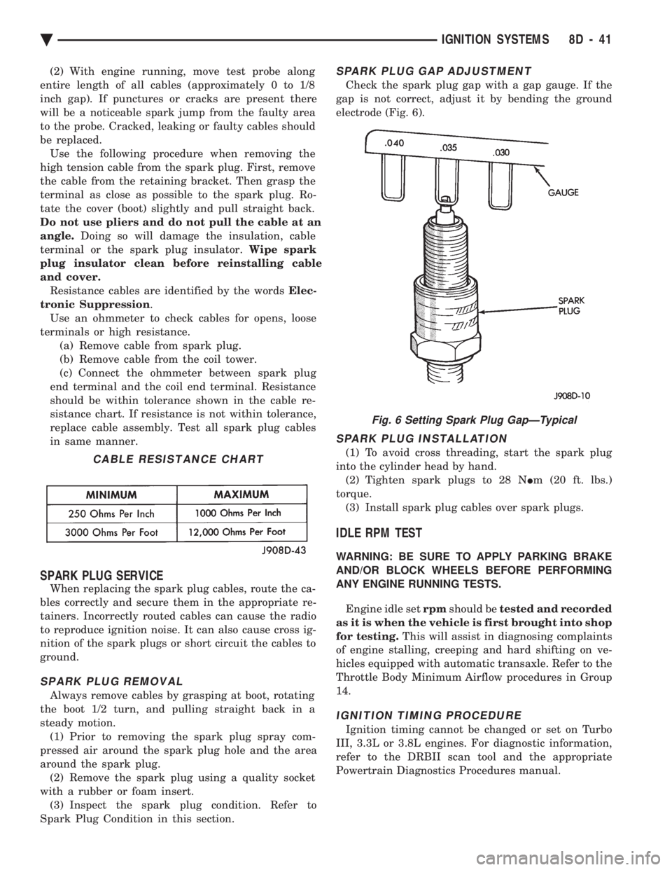
Check the spark plug gap with a gap gauge. If the
gap is not correct, adjust it by bending the ground
electrode (Fig. 6).
SPARK PLUG INSTALLATION
(1) To avoid cross threading, start the spark plug
into the cylinder head by hand. (2) Tighten spark plugs to 28 N Im (20 ft. lbs.)
torque. (3) Install spark plug cables over spark plugs.
IDLE RPM TEST
WARNING: BE SURE TO APPLY PARKING BRAKE
AND/OR BLOCK WHEELS BEFORE PERFORMING
ANY ENGINE RUNNING TESTS.
Engine idle set rpmshould be tested and recorded
as it is when the vehicle is first brought into shop
for testing. This will assist in diagnosing complaints
of engine stalling, creeping and hard shifting on ve-
hicles equipped with automatic transaxle. Refer to the
Throttle Body Minimum Airflow procedures in Group
14.
IGNITION TIMING PROCEDURE
Ignition timing cannot be changed or set on Turbo
III, 3.3L or 3.8L engines. For diagnostic information,
refer to the DRBII scan tool and the appropriate
Powertrain Diagnostics Procedures manual.
CABLE RESISTANCE CHART
Fig. 6 Setting Spark Plug GapÐTypical
Ä IGNITION SYSTEMS 8D - 41
Page 494 of 2438

shield washer fluid, door ajar for each door, and
trunk ajar. It also includes headlamp out, tail lamp
out, and brake lamp out warning lights (Fig. 3),
these lights are operated by a lamp outage module.
When there is no message center there is no door
ajar function.
TRAVELER
The traveler is a five function trip computer. It
uses vacuum fluorescent displays to display: trip
miles, instantaneous fuel economy, trip elapsed time,
trip average fuel economy and, estimate distance to
empty. It is located in the message center (Fig. 4).
WARNING LAMPS AND INDICATOR LIGHTS
The mechanical instrument cluster assemblies
have warning lamps and indicator lights for ten dif-
ferent systems. These include left and right turn sig-
nals, low fuel level, low oil pressure, high beam indicator, seat belt reminder, brake system, malfunc-
tion indicator (check engine) lamp, check gauges, an-
ti-lock system and air bag system indicator. The low oil pressure indicator replaces the Check
Gauges indicator in the cluster assembly without a
tachometer. In the cluster assembly with tachometer, Check
Gauges indictor illuminates in a warning situation.
This will notify driver to check for a problem in cool-
ant temperature, oil pressure or electrical systems.
CLUSTER AND GAUGE SERVICE AND TESTING
CAUTION: Disconnect battery cable. Before servic-
ing the instrument panel. Reconnect battery cable
when power is required for test purposes.
FUEL GAUGEÐFLEXIBLE FUEL
The flexible fuel vehicle uses a dampened fuel
gauge. Methanol fuel causes erratic gauge movement
if the proper gauge is not used. The unique fuel gauge may be identified by either
a green logo on the face of the gauge or by checking
the part number. Remove cluster from the instru-
ment panel and check the part number on top of the
cluster. Refer to Mechanical/Electronic Cluster Re-
moval for proper procedures. Refer to parts catalog
for proper part number.
Fig. 3 Message Center
Fig. 4 Traveler and Message Center
8E - 2 INSTRUMENT PANEL AND GAUGES Ä