check oil CHEVROLET PLYMOUTH ACCLAIM 1993 Repair Manual
[x] Cancel search | Manufacturer: CHEVROLET, Model Year: 1993, Model line: PLYMOUTH ACCLAIM, Model: CHEVROLET PLYMOUTH ACCLAIM 1993Pages: 2438, PDF Size: 74.98 MB
Page 555 of 2438
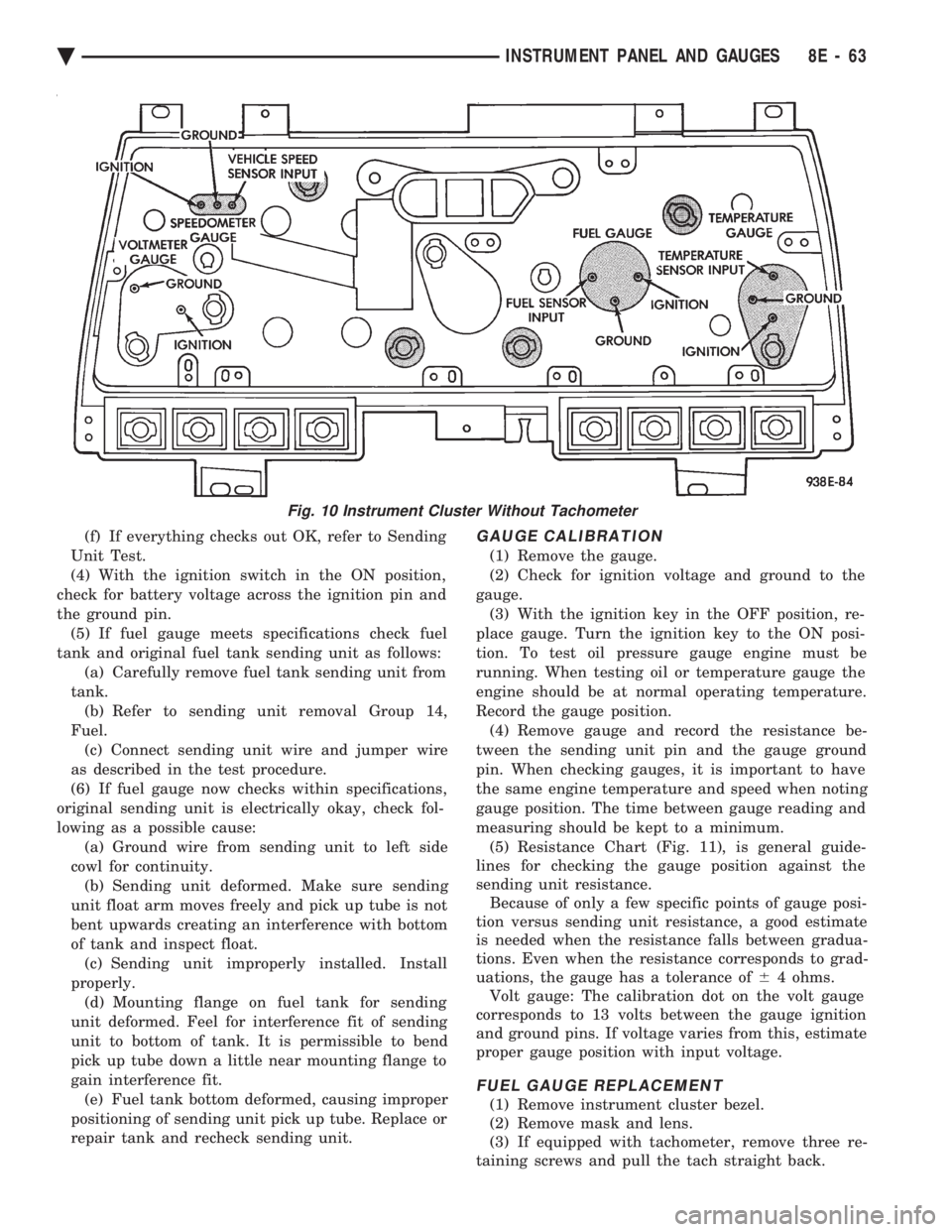
(f) If everything checks out OK, refer to Sending
Unit Test.
(4) With the ignition switch in the ON position,
check for battery voltage across the ignition pin and
the ground pin. (5) If fuel gauge meets specifications check fuel
tank and original fuel tank sending unit as follows: (a) Carefully remove fuel tank sending unit from
tank. (b) Refer to sending unit removal Group 14,
Fuel. (c) Connect sending unit wire and jumper wire
as described in the test procedure.
(6) If fuel gauge now checks within specifications,
original sending unit is electrically okay, check fol-
lowing as a possible cause: (a) Ground wire from sending unit to left side
cowl for continuity. (b) Sending unit deformed. Make sure sending
unit float arm moves freely and pick up tube is not
bent upwards creating an interference with bottom
of tank and inspect float. (c) Sending unit improperly installed. Install
properly. (d) Mounting flange on fuel tank for sending
unit deformed. Feel for interference fit of sending
unit to bottom of tank. It is permissible to bend
pick up tube down a little near mounting flange to
gain interference fit. (e) Fuel tank bottom deformed, causing improper
positioning of sending unit pick up tube. Replace or
repair tank and recheck sending unit.GAUGE CALIBRATION
(1) Remove the gauge.
(2) Check for ignition voltage and ground to the
gauge. (3) With the ignition key in the OFF position, re-
place gauge. Turn the ignition key to the ON posi-
tion. To test oil pressure gauge engine must be
running. When testing oil or temperature gauge the
engine should be at normal operating temperature.
Record the gauge position. (4) Remove gauge and record the resistance be-
tween the sending unit pin and the gauge ground
pin. When checking gauges, it is important to have
the same engine temperature and speed when noting
gauge position. The time between gauge reading and
measuring should be kept to a minimum. (5) Resistance Chart (Fig. 11), is general guide-
lines for checking the gauge position against the
sending unit resistance. Because of only a few specific points of gauge posi-
tion versus sending unit resistance, a good estimate
is needed when the resistance falls between gradua-
tions. Even when the resistance corresponds to grad-
uations, the gauge has a tolerance of 64 ohms.
Volt gauge: The calibration dot on the volt gauge
corresponds to 13 volts between the gauge ignition
and ground pins. If voltage varies from this, estimate
proper gauge position with input voltage.
FUEL GAUGE REPLACEMENT
(1) Remove instrument cluster bezel.
(2) Remove mask and lens.
(3) If equipped with tachometer, remove three re-
taining screws and pull the tach straight back.
Fig. 10 Instrument Cluster Without Tachometer
Ä INSTRUMENT PANEL AND GAUGES 8E - 63
Page 643 of 2438
LAMPS
CONTENTS
page page
BULB APPLICATION TABLE ............... 38
CONCEALED HEADLAMPS ................ 27
EXTERIOR LAMP SWITCHES AND HEADLAMP ALIGNMENT ........................... 3
EXTERIOR LAMP SYSTEMS .............. 25
EXTERIOR LAMPSÐAA BODY ............. 7
EXTERIOR LAMPSÐAC BODY ............ 10 EXTERIOR LAMPSÐAG BODY
............ 14
EXTERIOR LAMPSÐAJ BODY ............ 16
EXTERIOR LAMPSÐAP BODY ............ 19
EXTERIOR LAMPSÐAY-BODY ............ 22
GENERAL INFORMATION .................. 1
ILLUMINATED ENTRY SYSTEM ........... 33
GENERAL INFORMATION
Each vehicle is equipped with lamps used for illumi-
nating and indicating purposes. A circuit must have a
good ground to be complete. Circuit ground occurs
when the lamp socket makes contact with the metal
body. On vehicles with plastic lamps, a wire between
the socket and the body makes the grounds. When changing lamp bulbs, check the socket for
corrosion. If corrosion is present, clean contacts with a
wire brush and coat the inside of the socket with
Mopar tMulti-purpose Grease or equivalent.
CAUTION: Do not touch the glass of halogen bulbs
with fingers or any possibly oily surface, reduced
bulb life will result.
BODY IDENTIFICATION
Throughout this Group, references are made to the
vehicle family or body code. To decode the vehicle
identification plates, refer to the Introduction Section
at the front of this manual.
DIAGNOSTIC PROCEDURES
Begin electrical system failure diagnosis by testing
all related fuses and circuit breakers in the fuse block
and engine compartment. When a vehicle experiences problems with the head-
lamp system, verify the condition of the battery con-
nections, charging system, headlamp bulbs, wire con-
nectors, relay, high beam dimmer switch and headlamp
switch. Refer to Wiring Diagrams manual for compo-
nent locations and circuit information.
SYMPTOM
Headlamps are dim when engine is idling of
with ignition turned OFF. Canada cars must
have lamps ON. ACTION
² Clean battery terminal clamps and posts. Refer to
Group 8B, Battery/Starter/Generator Service for
proper procedures.
² Test charging system output. Refer to Group 8A,
Battery/Starting/Charging Systems Diagnostics for
proper testing procedures.
² Test for high resistance in headlamp circuits.
² Defective headlamp bulb.
SYMPTOM
Bulbs burn out frequently.
ACTION
² Test charging system output. Refer to Group 8A,
Battery/Starting/Charging Systems Diagnostics for
proper testing procedures.
² Check for loose or corroded connector terminals or
splices in headlamp circuits. Refer to Wiring Diagrams
manual for component and splice locations.
SYMPTOM
Headlamps are dim with engine running above
idle. Canada cars must have lamps ON.
ACTION
² Test charging system output. Refer to Group 8A,
Battery/Starting/Charging Systems Diagnostics for
proper testing procedures.
² Test for high resistance in headlamp circuits.
² Defective headlamp bulb.
SYMPTOM
Headlamps flash randomly.
ACTION
² Test for poor circuit ground.
² Test for high resistance in headlamp circuits.
Ä LAMPS 8L - 1
Page 680 of 2438
BULB APPLICATION TABLE
GENERAL INFORMATION
The following Bulb Application Table lists the
lamp title in bold print on the left side of the column.
The vehicle family and model codes are listed under
the lamp title. The trade number or part number is
listed on the right side of the column.
CAUTION: Do not use bulbs that have a higher can-
dle power than the bulb listed in the Bulb Applica-
tion Table. Damage to lamp can result. Do not touch halogen bulbs with fingers or other
possibly oily surfaces. Bulb life will be reduced .
EXTERIOR LAMPS
Back-up
AY/C-P ....................................................................921
AA/D-A, AC/C, AY/C-S .........................................922
AA/P-P-C, AJ/C, AP/D-P.....................................1156
AA/P-H, AC/D, AG/V, AY/C-P ...........................3157
Center High Mounted Stop
AA ...........................................................................921
AC, AG, AJ, AY, AP ............................................922
Cornering
AA, AY .................................................................3157
Fog
AA ......................................................................GE880
AP/D...................................................................GE893
AG, AP/P .................................................................H3
Front Side Marker
AA/P-H, AA/D, AC, AJ, AP, AY-S......................168
AA/P-PX, AA/C, AY-P ....................................194NA
Front Side Marker/Turn Sig.
AG....................................................................3157NA
Headlamp/Aero
AG, AJ-High Beam .............................................9005
AG, AJ-Low beam ...............................................9006
AA, AC/D, AP ......................................................9004
Headlamp/Sealed Low Beam
AC/C, AY ...........................................................H4703
Headlamp/Sealed High Beam
AC/C, AY ...........................................................H4701
License Plate
AA, AC/C, AG, AJ, AP, AY/C-S ..........................168
AC/D, AY/C-P.........................................................194
Park/Turn Signal
AC/C-D, AY/C-P, AY/C-S ..............................3157NA
AA/P-X-C, AC/C, AG, AY/C-P, AY/C-S ........194NA
AA/P-H-D ..............................................................3157
AJ, AP...................................................................2057
Rear Side Marker
AC/C, AG, AJ, AY/C-S-P ......................................168
AA/P-C-D, AC/D, AP, AY/CS (opt.) .....................916
Tail
AG ...........................................................................168
AJ, AY/C-P .............................................................916 Tail Reflector
AY ...........................................................................168
Tail/Stop/Turn Signal
AP ..........................................................................2057
AG, AC..................................................................3057
AA, AJ, AY ..........................................................3157
INTERIOR LAMPS
Some components have lamps that can only be ser-
viced by a Authorized Service Center (ASC) after the
component is removed from the vehicle. Contact local
dealer for location of nearest ASC. Chrysler vehicles
are equipped with a mechanical instrument cluster
(MIC) or an optional electronic instrument cluster
(EIC). If a bulb is unique to the MIC or EIC the ac-
ronym will follow the title.
INDICATOR LAMPS
Service procedures for the indicator lamps in the
instrument cluster are located in Group 8E, Instru-
ment Panel and Gauges. Air Bag (MIC)
AC, AY....................................................................103
AA, AG, AJ, AP ...............................................PC194
Antilock (MIC)
AA ...........................................................................103
AC, AG, AJ, AP, AY .......................................PC194
Antilock (EIC)
AA, AY ..............................................................PC194
AJ ............................................................................103
Brake (MIC)
AA ...........................................................................103
AC, AG, AJ, AP, AY .......................................PC194
Brake (EIC)
AA, AY ..............................................................PC194
AJ ............................................................................103
Check Engine (MIC)
AA ...........................................................................103
AC, AG, AJ, AP, AY .......................................PC194
Check Engine (EIC)
AA, AY ..............................................................PC194
AJ ............................................................................103
Check Gauges
All .......................................................................PC194
Door Open
AA, AC, AY .............................................................74
AP ............................................................................161
AG, AJ ............................................................4437661
Fog Lamp (MIC)
AG ......................................................................PC194
High Beam (MIC)
AA ...........................................................................103
AC, AG, AJ, AP, AY .......................................PC194
High Beam (EIC)
AA, AY ..............................................................PC194
Lamp Outage
8L - 38 LAMPS Ä
Page 1568 of 2438
The MOPAR Silicone Rubber Adhesive Sealant
gasket material or equivalent should be applied in a
continuous bead approximately 3mm (0.120 inch) in
diameter. All mounting holes must be circled. For
corner sealing, a 3.17 or 6.35 mm (1/8 or 1/4 inch.)
drop is placed in the center of the gasket contact
area. Uncured sealant may be removed with a shop
towels. Components should be torqued in place while
the sealant is still wet to the touch (within 10 min-
utes). The usage of a locating dowel is recommended
during assembly to prevent smearing of material off
location.
CRANKSHAFT SPROCKET BOLT ACCESS PLUG
An Access plug is located in the right inner fender
shield. Remove the plug and insert proper size
socket, extension and rachet, when crankshaft rota-
tion is necessary.
ENGINE PERFORMANCE
If a loss of performance is noticed, ignition timing
should be checked. If ignition timing is retarded by
9, 18 or 27É indicating 1, 2 or 3 (timing belt or chain)
teeth may have skipped, then, camshaft and acces-
sory shaft timing with the crankshaft should be
checked. Refer to Engine Timing Sprockets and Oil
Seals of the Engine Section. To provide best vehicle performance and lowest ve-
hicle emissions, it is most important that the tune-up
be done accurately. Use the specifications listed on
the Vehicle Emission Control Information label
found in the engine compartment. (1) Test cranking amperage draw. See Starting
Motor Cranking Amperage Draw Electrical Section
of this manual. (2) Tighten the intake manifold bolts to specifica-
tions. (3) Perform cylinder compression test.(a) Check engine oil level and add oil if neces-
sary. (b) Drive the vehicle until engine reaches normal
operating temperature. (c) Select a route free from traffic and other
forms of congestion, observe all traffic laws, and ac-
celerate through the gears several times briskly.
CAUTION: Do not overspeed the engine. The higher
engine speed may help clean out valve seat deposits
which can prevent accurate compression readings.
(d) Remove all spark plugs from engine. As
spark plugs are being removed, check electrodes for
abnormal firing indicators fouled, hot, oily, etc.
Record cylinder number of spark plug for future
reference. (e) Disconnect coil wire from distributor and se-
cure to good ground to prevent a spark from start- ing a fire (Conventional Ignition System). For Direct
Ignition System DIS disconnect the coil connector. (f) Be sure throttle blade is fully open during the
compression check. (g) Insert compression gage adaptor into the #1
spark plug hole in cylinder head. Crank engine until
maximum pressure is reached on gage. Record this
pressure as #1 cylinder pressure. (h) Repeat Step G for all remaining cylinders.
(i) Compression should not be less than (689kPa)
100 psi and not vary more than 25 percent from
cylinder to cylinder. (j) If one or more cylinders have abnormally low
compression pressures, repeat steps 3b through 3h. (k) If the same cylinder or cylinders repeat an
abnormally low reading on the second compression
test, it could indicate the existence of a problem in
the cylinder in question.
The recommended compression pressures are
to be used only as a guide to diagnosing engine
problems. An engine should not be disassembled
to determine the cause of low compression un-
less some malfunction is present. (4) Clean or replace spark plugs as necessary and
adjust gap as specified in Electrical Group 8. Tighten to
specifications. (5) Test resistance of spark plug cables. Refer to
Ignition System Secondary Circuit Inspection Electri-
cal Section Group 8. (6) Inspect the primary wire. Test coil output volt-
age, primary and secondary resistance. Replace parts
as necessary. Refer to Ignition System and make nec-
essary adjustment. (7) Ignition timing should be set to specifications.
(See Specification Label in engine compartment). (8) Test fuel pump for pressure and vacuum. Refer to
Fuel System Group 14, Specifications. (9) The air filter elements should be replaced as
specified in Lubrication and Maintenance, Group 0. (10) Inspect crankcase ventilation system as out
lined in Lubrication and Maintenance, Group 0. For
emission controls see Emission Controls Group 25 for
service procedures. (11) Inspect and adjust accessory belt drives refer-
ring to Accessory Belt Drive in Cooling System, Group
7 for proper adjustments. (12) Road test vehicle as a final test.
HONING CYLINDER BORES
Before honing, stuff plenty of clean shop towels
under the bores, over the crankshaft to keep abrasive
materials from entering crankcase area. (1) Used carefully, the cylinder bore resizing hone
C-823 equipped with 220 grit stones, is the best tool for
this job. In addition to deglazing, it will reduce taper
and out-of-round as well as removing light
9 - 2 ENGINE Ä
Page 1569 of 2438

scuffing, scoring or scratches. Usually a few strokes
will clean up a bore and maintain the required limits.(2) Deglazing of the cylinder walls may be done
using a cylinder surfacing hone, Tool C-3501, equipped
with 280 grit stones (C-3501-3810) if the cylinder bore
is straight and round. 20-60 strokes depending on the
bore condition will be sufficient to provide a satisfac-
tory surface. Inspect cylinder walls after each 20
strokes. Using a light honing oil available from major
oil distributors. Do not use engine or transmission
oil, mineral spirits or kerosene. (3) Honing should be done by moving the hone up
and down fast enough to get a cross-hatch pattern.
When hone marks intersectat 50-60 degrees, the
cross hatch angle is most satisfactory for proper seat-
ing of rings (Fig. 1).
(4) A controlled hone motor speed between 200-300
RPM is necessary to obtain the proper cross-hatch
angle. The number of up and down strokes per minute
can be regulated to get the desired 50-60 degree angle.
Faster up and down strokes increase the cross-hatch
angle. (5) After honing, it is necessary that the block be
cleaned again to remove all traces of abrasive.
CAUTION: Be sure all abrasive are removed from
engine parts after honing. It is recommended that a
solution of soap and hot water be used with a brush
and the parts then thoroughly dried. The bore can be
considered clean when it can be wiped clean with a
white cloth and cloth remains clean. Oil the bores
after cleaning to prevent rusting.
MEASURING MAIN BEARING CLEARANCE AND
CONNECTING ROD BEARING CLEARANCE
PLASTIGAGE METHOD
Engine crankshaft bearing clearances can be deter-
mined by use of Plastigage or equivalent. The follow-
ing is the recommended procedure for the use of
Plastigage: (1) Remove oil film from surface to be checked.
Plastigage is soluble in oil. (2) The total clearance of the main bearingscan
only be determined by removing the weight of the
crankshaft. This can be accomplished by either of
two methods: PREFERRED METHOD Ð Shimming the bear-
ings adjacent to the bearing to be checked in order to
remove the clearance between upper bearing shell
and the crankshaft. This can be accomplished by
placing a minimum of 0.254mm (.010 inch) shim (e.
g. cardboard, matchbook cover, etc.) between the
bearing shell and the bearing cap on the adjacent
bearings and snugging bolts to 14-20 N Im (10-15
ft.lb.)
² When checking #1 main brg shim #2 main brg
²
When checking #2 main brg shim # 1 & 3 main brg
²When checking #3 main brg shim #2 & 4 main brg
²When checking #4 main brg shim #3 & 5 main brg
²When checking #5 main brg shim #4 main brg
Fig. 2 Plastigage Placed in Lower Shell
Fig. 3 Clearance Measurement
Fig. 1 Cylinder Bore Cross-Hatch Pattern
Ä ENGINE 9 - 3
Page 1570 of 2438

REMOVE ALL SHIMS BEFORE REASSEM-
BLING ENGINE ALTERNATIVE METHOD Ð With the weight of
the crankshaft being supported by a jack under the
counterweight adjacent to the bearing being checked. (3) Place a piece of Plastigage across the entire
width of the bearing shell in the cap approximately
6.35 mm (1/4 inch) off center and away from the oil
holes (Fig. 2). (In addition, suspect areas can be
checked by placing the Plastigage in the suspect area).
Torque the bearing cap bolts of the bearing being
checked to the proper specifications. (4) Remove the bearing cap and compare the width
of the flattened Plastigage (Fig. 3) with the metric scale
provided on the package. Locate the band closest to the
same width. This band shows the amount of clearance
in thousandths of a millimeter. Differences in readings
between the ends indicate the amount of taper present.
Record all readings taken. Refer to Engine Specifica-
tions. Plastic-Gage generally is accompanied by
two scales. One scale is in inches, the other is a
metric scale. (5) Plastigage is available in a variety of clearance
ranges. The 0.025-0.076mm (.001-.003 inch) is usually
the most appropriate for checking engine bearing
proper specifications.
CONNECTING ROD BEARING CLEARANCE
Engine crankshaft bearing clearances can be deter-
mined by use of Plastigage or equivalent. The following
is the recommended procedure for the use of Plasti-
gage: (1) Rotate the crankshaft until the connecting rod to
be checked is at the bottom of its stroke. (2) Remove oil film from surface to be checked.
Plastigage is soluble in oil. (3) Place a piece of Plastigage across the entire
width of the bearing shell in the bearing cap approxi-
mately 6.35 mm (1/4 inch.) off center and away from
the oil hole (Fig. 2). In addition, suspect areas can be
checked by placing plastigage in the suspect area. (4) Before assembling the rod cap with Plastigage in
place, the crankshaft must be rotated until the con-
necting being checked starts moving toward the top of
the engine. Only then should the cap be assembled and
torqued to specifications. Do not rotate the crank-
shaft while assembling the cap or the Plastigage
may be smeared, giving inaccurate results. (5) Remove the bearing cap and compare the width
of the flattened Plastigage (Fig. 3) with the metric
scale provided on the package. Locate the band closest
to the same width. This band shows the amount
of clearance in thousandths of a millimeter. Differences
in readings between the ends indicate the amount
of taper present. Record all readings taken.
Refer to Engine Specifications. Plastigage generally is accompanied by two scales. One scale is in
inches, the other is a metric scale. (6) Plastigage is available in a variety of clearance
ranges. The 0.025-0.076mm (.001-.003 inch) is usually
the most appropriate for checking engine bearing
proper specifications.
LASH ADJUSTER (TAPPET) NOISE DIAGNOSIS
A tappet-like noise may be produced from several
items. Check the following items. (1) Engine oil level too high or too low. This may
cause aerated oil to enter the adjusters and cause them
to be spongy. (2) Insufficient running time after rebuilding cylin-
der head. Low speed running up to 1 hour may be
required. During this time, turn engine off and let set for a few
minutes before restarting. Repeat this several times
after engine has reached normal operating tempera-
ture. (3) Low oil pressure.
(4) The oil restrictor pressed into the vertical oil
passage to the cylinder head of Balance Shaft Engines
Only is plugged with debris. (5) Air ingested into oil due to broken or cracked oil
pump pick up. (6) Worn valve guides.
(7) Rocker arm ears contacting valve spring retainer
(2.2/2.5L engines). (8) Rocker arm loose, adjuster or tappet stuck or at
maximum extension and still leaves lash in the system. (9) Faulty lash adjuster or tappet.(a) Check for sponginess while still installed in
engine. Depress part of rocker arm just over adjuster
or pushrod . Normal adjusters should feel very firm.
Spongy adjusters can be depressed to the bottomed
position easily. (b) Remove suspected lash adjuster or tappet, pry
off retainer cap or snap ring and disassemble. Do
not reuse retainer caps . Do not interchange parts
and make sure that care and cleanliness is exercised
in the handling of parts. (c) Clean out dirt and varnish with solvent.
(d) Reassemble with engine oil.
(e) Check for sponginess.
(f) If still spongy, replace with new adjuster.
REPAIR OF DAMAGED OR WORN THREADS
Damaged or worn threads (including aluminum head
spark plug threads) can be repaired. Essentially, this
repair consists of drilling out worn or damaged
threads, tapping the hole with a special Heli-Coil (or
equivalent) Tap, and installing an insert into the
tapped hole. This brings the hole back to its original
thread size.
9 - 4 ENGINE Ä
Page 1571 of 2438
CAUTION: Be sure that the tapped holes maintain
the original centerline.
Heli-Coil tools and inserts are readily available
from automotive parts jobbers.
HYDROSTATIC LOCKED ENGINE
When an engine is suspected to be hydrostaticly
locked, regardless of what caused the problem, these
steps should be used.
CAUTION: Do Not Use Starter Motor To Rotate En-
gine, severe damage may occur.
(1) Inspect air cleaner, induction system and in-
take manifold to insure system is dry and clear of
foreign material. (2) Remove negative battery cable.
(3) Place a shop towel around the spark plugs
when removing them from the engine. This will
catch any fluid that may possibly be in the cylinder
under pressure. (4) With all spark plugs removed, rotate engine
crankshaft using a breaker bar and socket. (5) Identify the fluid in the cylinder(s) (i.e., cool-
ant, fuel, oil or other). (6) Make sure all fluid has been removed from the
cylinders. Inspect engine for damage (i.e., Connecting
Rods, Pistons, Valves etc.) (7) Repair engine or components as necessary to
prevent this problem from occurring again.
CAUTION: Squirt approximately 1 teaspoon of oil
into cylinders, rotate engine to lubricate the cylin-
der walls to prevent damage on restart.
(8) Install new spark plugs.
(9) Drain engine oil and remove oil filter.
(10) Fill engine with specified amount of approved
oil and install new oil filter. (11) Connect negative battery cable.
(12) Start engine and check for any leaks.
Ä ENGINE 9 - 5
Page 1574 of 2438
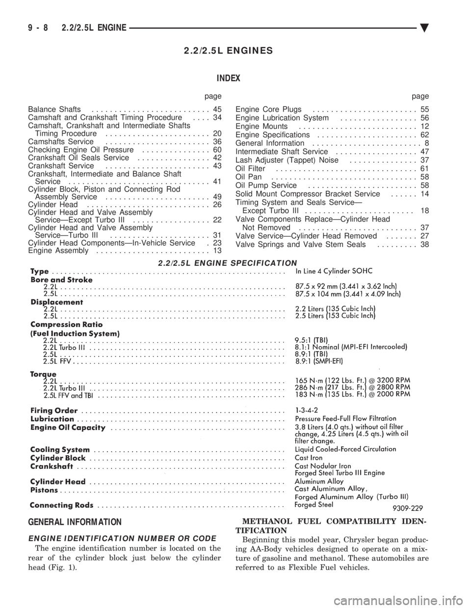
2.2/2.5L ENGINES INDEX
page page
Balance Shafts .......................... 45
Camshaft and Crankshaft Timing Procedure .... 34
Camshaft, Crankshaft and Intermediate Shafts Timing Procedure ....................... 20
Camshafts Service ....................... 36
Checking Engine Oil Pressure ............... 60
Crankshaft Oil Seals Service ................ 42
Crankshaft Service ....................... 43
Crankshaft, Intermediate and Balance Shaft Service ............................... 41
Cylinder Block, Piston and Connecting Rod Assembly Service ....................... 49
Cylinder Head ........................... 26
Cylinder Head and Valve Assembly ServiceÐExcept Turbo III ................. 22
Cylinder Head and Valve Assembly ServiceÐTurbo III ...................... 31
Cylinder Head ComponentsÐIn-Vehicle Service . 23
Engine Assembly ......................... 13 Engine Core Plugs
....................... 55
Engine Lubrication System ................. 56
Engine Mounts .......................... 12
Engine Specifications ...................... 62
General Information ........................ 8
Intermediate Shaft Service .................. 47
Lash Adjuster (Tappet) Noise ............... 37
Oil Filter ............................... 61
Oil Pan ................................ 58
Oil Pump Service ........................ 58
Solid Mount Compressor Bracket Service ...... 14
Timing System and Seals ServiceÐ Except Turbo III ........................ 18
Valve Components ReplaceÐCylinder Head Not Removed .......................... 37
Valve ServiceÐCylinder Head Removed ....... 27
Valve Springs and Valve Stem Seals ......... 38
GENERAL INFORMATION
ENGINE IDENTIFICATION NUMBER OR CODE
The engine identification number is located on the
rear of the cylinder block just below the cylinder
head (Fig. 1). METHANOL FUEL COMPATIBILITY IDEN-
TIFICATION Beginning this model year, Chrysler began produc-
ing AA-Body vehicles designed to operate on a mix-
ture of gasoline and methanol. These automobiles are
referred to as Flexible Fuel vehicles.
2.2/2.5L ENGINE SPECIFICATION
9 - 8 2.2/2.5L ENGINE Ä
Page 1579 of 2438
² Drive shaft distress: See Driveshafts in Suspension,
Group 2.
² Any front end structural damage (after repair).
² Insulator replacement.
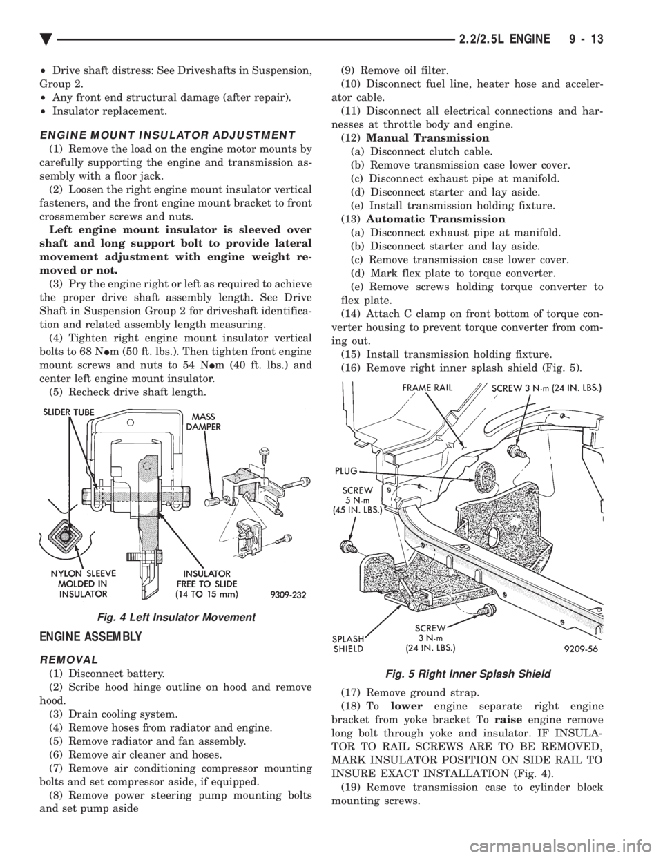
ENGINE MOUNT INSULATOR ADJUSTMENT
(1) Remove the load on the engine motor mounts by
carefully supporting the engine and transmission as-
sembly with a floor jack. (2) Loosen the right engine mount insulator vertical
fasteners, and the front engine mount bracket to front
crossmember screws and nuts. Left engine mount insulator is sleeved over
shaft and long support bolt to provide lateral
movement adjustment with engine weight re-
moved or not. (3) Pry the engine right or left as required to achieve
the proper drive shaft assembly length. See Drive
Shaft in Suspension Group 2 for driveshaft identifica-
tion and related assembly length measuring. (4) Tighten right engine mount insulator vertical
bolts to 68 N Im (50 ft. lbs.). Then tighten front engine
mount screws and nuts to 54 N Im (40 ft. lbs.) and
center left engine mount insulator. (5) Recheck drive shaft length.
ENGINE ASSEMBLY
REMOVAL
(1) Disconnect battery.
(2) Scribe hood hinge outline on hood and remove
hood. (3) Drain cooling system.
(4) Remove hoses from radiator and engine.
(5) Remove radiator and fan assembly.
(6) Remove air cleaner and hoses.
(7) Remove air conditioning compressor mounting
bolts and set compressor aside, if equipped. (8) Remove power steering pump mounting bolts
and set pump aside (9) Remove oil filter.
(10) Disconnect fuel line, heater hose and acceler-
ator cable. (11) Disconnect all electrical connections and har-
nesses at throttle body and engine. (12) Manual Transmission
(a) Disconnect clutch cable.
(b) Remove transmission case lower cover.
(c) Disconnect exhaust pipe at manifold.
(d) Disconnect starter and lay aside.
(e) Install transmission holding fixture.
(13) Automatic Transmission
(a) Disconnect exhaust pipe at manifold.
(b) Disconnect starter and lay aside.
(c) Remove transmission case lower cover.
(d) Mark flex plate to torque converter.
(e) Remove screws holding torque converter to
flex plate.
(14) Attach C clamp on front bottom of torque con-
verter housing to prevent torque converter from com-
ing out. (15) Install transmission holding fixture.
(16) Remove right inner splash shield (Fig. 5).
(17) Remove ground strap.
(18) To lowerengine separate right engine
bracket from yoke bracket To raiseengine remove
long bolt through yoke and insulator. IF INSULA-
TOR TO RAIL SCREWS ARE TO BE REMOVED,
MARK INSULATOR POSITION ON SIDE RAIL TO
INSURE EXACT INSTALLATION (Fig. 4). (19) Remove transmission case to cylinder block
mounting screws.Fig. 5 Right Inner Splash Shield
Fig. 4 Left Insulator Movement
Ä 2.2/2.5L ENGINE 9 - 13
Page 1587 of 2438
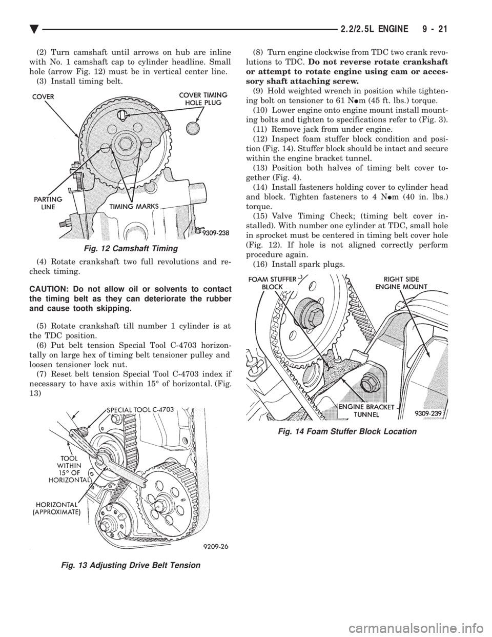
(2) Turn camshaft until arrows on hub are inline
with No. 1 camshaft cap to cylinder headline. Small
hole (arrow Fig. 12) must be in vertical center line. (3) Install timing belt.
(4) Rotate crankshaft two full revolutions and re-
check timing.
CAUTION: Do not allow oil or solvents to contact
the timing belt as they can deteriorate the rubber
and cause tooth skipping.
(5) Rotate crankshaft till number 1 cylinder is at
the TDC position. (6) Put belt tension Special Tool C-4703 horizon-
tally on large hex of timing belt tensioner pulley and
loosen tensioner lock nut. (7) Reset belt tension Special Tool C-4703 index if
necessary to have axis within 15É of horizontal. (Fig.
13) (8) Turn engine clockwise from TDC two crank revo-
lutions to TDC. Do not reverse rotate crankshaft
or attempt to rotate engine using cam or acces-
sory shaft attaching screw. (9) Hold weighted wrench in position while tighten-
ing bolt on tensioner to 61 N Im (45 ft. lbs.) torque.
(10) Lower engine onto engine mount install mount-
ing bolts and tighten to specifications refer to (Fig. 3). (11) Remove jack from under engine.
(12) Inspect foam stuffer block condition and posi-
tion (Fig. 14). Stuffer block should be intact and secure
within the engine bracket tunnel. (13) Position both halves of timing belt cover to-
gether (Fig. 4). (14) Install fasteners holding cover to cylinder head
and block. Tighten fasteners to 4 N Im (40 in. lbs.)
torque. (15) Valve Timing Check; (timing belt cover in-
stalled). With number one cylinder at TDC, small hole
in sprocket must be centered in timing belt cover hole
(Fig. 12). If hole is not aligned correctly perform
procedure again. (16) Install spark plugs.
Fig. 12 Camshaft Timing
Fig. 13 Adjusting Drive Belt Tension
Fig. 14 Foam Stuffer Block Location
Ä 2.2/2.5L ENGINE 9 - 21