bulb CHEVROLET PLYMOUTH ACCLAIM 1993 Service Manual
[x] Cancel search | Manufacturer: CHEVROLET, Model Year: 1993, Model line: PLYMOUTH ACCLAIM, Model: CHEVROLET PLYMOUTH ACCLAIM 1993Pages: 2438, PDF Size: 74.98 MB
Page 33 of 2438
COMPONENT AND SYSTEM INDEX
Name Group-page Name Group-page
AUDIO SYSTEM ............................ 8F-1
ANTENNAS ............................ 8F-20
COMPACT DISC PLAYER ................... 8F-30
RADIOS ............................... 8F-1
SPEAKERS ............................. 8F-24
BATTERY/STARTER/GENERATOR SERVICE ..........8B-1
BATTERY REMOVAL, INSTALLATION AND SERVICE . . 8B-1
GENERATOR ............................ 8B-9
SPECIFICATIONS ........................ 8B-12
STARTER .............................. 8B-4
BATTERY/STARTING/CHARGING SYSTEMS DIAGNOSTICS ........................... 8A-1
BATTERY TEST PROCEDURES ON-VEHICLE .......8A-3
FAULT CODESÐON BOARD DIAGNOSTICS .......8A-23
GENERAL INFORMATION .................... 8A-1
GENERATOR TEST PROCEDURES ON VEHICLE ....8A-19
IGNITION OFF DRAW (IOD) ..................8A-9
SPECIFICATIONS ........................ 8A-28
STARTER TEST PROCEDURES ON VEHICLE ......8A-11
CHIME WARNING/REMINDER SYSTEM ............8U-1
EMISSION CONTROL SYSTEMS .................25-1
EVAPORATIVE EMISSION CONTROLS ...........25-1
EXHAUST EMISSION CONTROLS ..............25-17
FUEL SYSTEMS ............................ 14-1
2.2L TURBO III MULTI-PORT FUEL INJECTIONÐ GENERAL DIAGNOSIS ................... 14-95
2.2L TURBO III MULTI-PORT FUEL INJECTIONÐ ON-BOARD DIAGNOSTICS ................14-100
2.2L TURBO III MULTI-PORT FUEL INJECTIONÐ SERVICE PROCEDURES .................14-107
2.2L TURBO III MULTI-PORT FUEL INJECTIONÐ SYSTEM OPERATION .................... 14-83
2.2L/2.5L SINGLE POINT FUEL INJECTIONÐ GENERAL DIAGNOSIS ................... 14-35
2.2L/2.5L SINGLE POINT FUEL INJECTIONÐ ON-BOARD DIAGNOSTICS .................14-41
2.2L/2.5L SINGLE POINT FUEL INJECTIONÐ SERVICE PROCEDURES .................. 14-48
2.2L/2.5L SINGLE POINT FUEL INJECTIONÐ SYSTEM OPERATION .................... 14-24
2.5L FLEXIBLE FUEL MULTI-PORT FUEL INJECTIONÐGENERAL DIAGNOSIS ..........14-66
2.5L FLEXIBLE FUEL MULTI-PORT FUEL INJECTIONÐON-BOARD DIAGNOSTICS ........14-70
2.5L FLEXIBLE FUEL MULTI-PORT FUEL INJECTIONÐSERVICE PROCEDURES .........14-77
2.5L FLEXIBLE FUEL MULTI-PORT FUEL INJECTIONÐSYSTEM OPERATION ...........14-55
3.0L MULTI-PORT FUEL INJECTIONÐGENERAL DIAGNOSIS .......................... 14-125
3.0L MULTI-PORT FUEL INJECTIONÐON-BOARD DIAGNOSTICS ........................ 14-130
3.0L MULTI-PORT FUEL INJECTIONÐSERVICE PROCEDURES ........................ 14-138
3.0L MULTI-PORT FUEL INJECTIONÐSYSTEM OPERATION ......................... 14-113
3.3L AND 3.8L MULTI-PORT FUEL INJECTIONÐ GENERAL DIAGNOSIS ................... 14-157 3.3L AND 3.8L MULTI-PORT FUEL INJECTIONÐ
ON-BOARD DIAGNOSTICS ................14-162
3.3L AND 3.8L MULTI-PORT FUEL INJECTIONÐ SERVICE PROCEDURES .................14-169
3.3L AND 3.8L MULTI-PORT FUEL INJECTIONÐ SYSTEM OPERATION ................... 14-145
ACCELERATOR PEDAL AND THROTTLE CABLE ....14-21
FUEL DELIVERY SYSTEM .................... 14-3
FUEL TANKS ........................... 14-14
GENERAL INFORMATION .................... 14-1
SPECIFICATIONS ........................ 14-178
HORNS ................................. 8G-1
IGNITION SYSTEMS ......................... 8D-1
2.2L TBI, 2.5L TBI, 2.5L MPI AND 3.0L IGNITION SYSTEMSÐDIAGNOSTIC PROCEDURES .......8D-11
2.2L TBI, 2.5L TBI, 2.5L MPI AND 3.0L IGNITION SYSTEMSÐSERVICE PROCEDURES ..........8D-14
2.2L TBI, 2.5L TBI, 2.5L MPI AND 3.0L IGNITION SYSTEMSÐSYSTEM OPERATION ............8D-1
2.2L TURBO III, 3.3L AND 3.8L IGNITION SYSTEMÐDIAGNOSTIC PROCEDURES ........8D-35
2.2L TURBO III, 3.3L AND 3.8L IGNITION SYSTEMÐSYSTEM OPERATION ............8D-24
2.2L TURBO III, 3.3L AND 3.8L IGNITION SYSTEMSÐSERVICE PROCEDURES ..........8D-39
IGNITION SWITCH ....................... 8D-45
SPECIFICATIONS ........................ 8D-47
INSTRUMENT PANEL AND GAUGES ...............8E-1
AA BODY .............................. 8E-1
AC AND AY BODIES ...................... 8E-23
AG AND AJ BODIES ...................... 8E-42
AP BODY ............................. 8E-58
LAMPS .................................. 8L-1
BULB APPLICATION TABLE ..................8L-38
CONCEALED HEADLAMPS ..................8L-27
EXTERIOR LAMP SWITCHES AND HEADLAMP ALIGNMENT ........................... 8L-3
EXTERIOR LAMP SYSTEMS .................8L-25
EXTERIOR LAMPSÐAA BODY ................8L-7
EXTERIOR LAMPSÐAC BODY ...............8L-10
EXTERIOR LAMPSÐAG BODY ...............8L-14
EXTERIOR LAMPSÐAJ BODY ................8L-16
EXTERIOR LAMPSÐAP BODY ...............8L-19
EXTERIOR LAMPSÐAY-BODY ................8L-22
GENERAL INFORMATION .................... 8L-1
ILLUMINATED ENTRY SYSTEM ...............8L-33
OVERHEAD CONSOLE ........................ 8C-1
AA BODY .............................. 8C-1
AC AND AY BODY ........................ 8C-6
AG AND AJ BODIES ...................... 8C-13
AP BODY ............................. 8C-21
POWER LOCKS ............................ 8P-1
POWER MIRRORS ..........................8T-1
POWER SEATS ............................ 8R-1
POWER WINDOWS .......................... 8S-1
REAR WINDOW DEFOGGER .................... 8N-1
RESTRAINT SYSTEMS ....................... 8M-1
TURN SIGNALS AND HAZARD WARNING FLASHER ....8J-1
VEHICLE SPEED CONTROL .................... 8H-1
Page 176 of 2438
HYDRAULIC SYSTEM CONTROL VALVES INDEX
page page
ABS Brake Proportioning Valve Operation ...... 27
General Information ....................... 26
Hydraulic System Service Procedures ......... 27 Non-ABS Proportioning Unit Operation
........ 26
Pressure Differential Warning Light Switch ...... 26
Testing ABS Proportioning Valves ............ 29
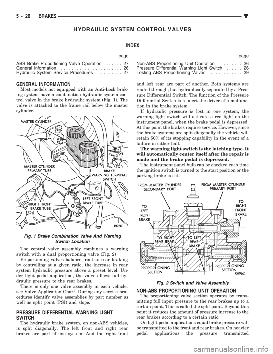
GENERAL INFORMATION
Most models not equipped with an Anti-Lock brak-
ing system have a combination hydraulic system con-
trol valve in the brake hydraulic system (Fig. 1). The
valve is attached to the frame rail below the master
cylinder.
The control valve assembly combines a warning
switch with a dual proportioning valve (Fig. 2) Proportioning valves balance front to rear braking
by controlling at a given ratio, the increase in rear
system hydraulic pressure above a preset level. Un-
der light pedal application, the valve allows full hy-
draulic pressure to the rear brakes. There is only one valve assembly in each vehicle,
see Valve Application Chart. During any service pro-
cedures identify valve assemblies by part number as
well as split point (PSI) and slope.
PRESSURE DIFFERENTIAL WARNING LIGHT
SWITCH
The hydraulic brake system, on non-ABS vehicles,
is split diagonally. The left front and right rear
brakes are part of one system. And the right front and left rear are part of another. Both systems are
routed through, but hydraulically separated by a Pres-
sure Differential Switch. The function of the Pressure
Differential Switch is to alert the driver of a malfunc-
tion in the brake system. If hydraulic pressure is lost in one system, the
warning light switch will activate a red light on the
instrument panel, when the brake pedal is depressed.
At this point the brakes require service. However, since
the brake systems are split diagonally the vehicle will
retain 50% of its stopping capability in the event of a
failure in either half. The warning light switch is the latching type. It
will automatically center itself after the repair is
made and the brake pedal is depressed. The instrument panel bulb can be checked each time
the ignition switch is turned to the start position or the
parking brake is set.
NON-ABS PROPORTIONING UNIT OPERATION
The proportioning valve section operates by trans-
mitting full input pressure to the rear brakes up to a
certain point. This is called the split point. Beyond this
point it reduces the amount of pressure increase to the
rear brakes according to a certain ratio. On light pedal applications equal brake pressure will
be transmitted to the front and rear brakes. On heavier
pedal applications the pressure transmitted
Fig. 1 Brake Combination Valve And Warning Switch Location
Fig. 2 Switch and Valve Assembly
5 - 26 BRAKES Ä
Page 177 of 2438
to the rear will be lower than the front brakes. This will
prevent premature rear wheel lock-up and skid. If
hydraulic pressure is lost in one half of the diagonally
split system, the operation of the proportioning valve
in the remaining half is not effected.
ABS BRAKE PROPORTIONING VALVE OPERATION
On vehicles using the ABS braking system, screw in
proportioning valves are used in place of the conven-
tional differential pressure/proportioning valve. Each rear brake circuit has its own screw-in propor-
tioning valve which is attached to the rear brake outlet
ports of the hydraulic assembly. These valves limit
brake pressure to the rear brakes after a certain
pressure is reached. This improves front to rear brake
balance during normal braking.
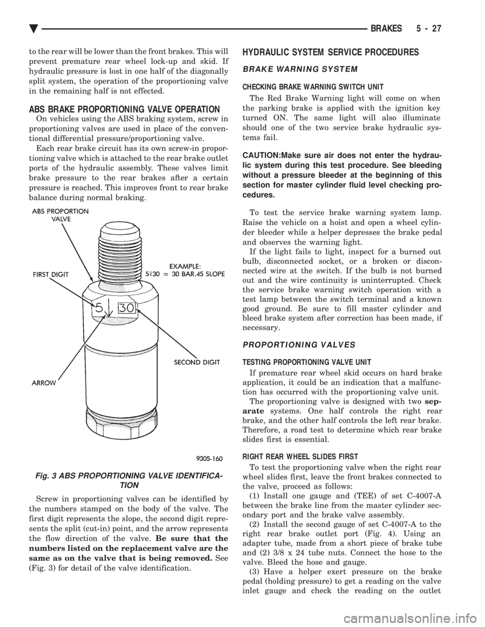
Screw in proportioning valves can be identified by
the numbers stamped on the body of the valve. The
first digit represents the slope, the second digit repre-
sents the split (cut-in) point, and the arrow represents
the flow direction of the valve. Be sure that the
numbers listed on the replacement valve are the
same as on the valve that is being removed. See
(Fig. 3) for detail of the valve identification.
HYDRAULIC SYSTEM SERVICE PROCEDURES
BRAKE WARNING SYSTEM
CHECKING BRAKE WARNING SWITCH UNIT
The Red Brake Warning light will come on when
the parking brake is applied with the ignition key
turned ON. The same light will also illuminate
should one of the two service brake hydraulic sys-
tems fail.
CAUTION:Make sure air does not enter the hydrau-
lic system during this test procedure. See bleeding
without a pressure bleeder at the beginning of this
section for master cylinder fluid level checking pro-
cedures.
To test the service brake warning system lamp.
Raise the vehicle on a hoist and open a wheel cylin-
der bleeder while a helper depresses the brake pedal
and observes the warning light. If the light fails to light, inspect for a burned out
bulb, disconnected socket, or a broken or discon-
nected wire at the switch. If the bulb is not burned
out and the wire continuity is uninterrupted. Check
the service brake warning switch operation with a
test lamp between the switch terminal and a known
good ground. Be sure to fill master cylinder and
bleed brake system after correction has been made, if
necessary.
PROPORTIONING VALVES
TESTING PROPORTIONING VALVE UNIT
If premature rear wheel skid occurs on hard brake
application, it could be an indication that a malfunc-
tion has occurred with the proportioning valve unit. The proportioning valve is designed with two sep-
arate systems. One half controls the right rear
brake, and the other half controls the left rear brake.
Therefore, a road test to determine which rear brake
slides first is essential.
RIGHT REAR WHEEL SLIDES FIRST To test the proportioning valve when the right rear
wheel slides first, leave the front brakes connected to
the valve, proceed as follows: (1) Install one gauge and (TEE) of set C-4007-A
between the brake line from the master cylinder sec-
ondary port and the brake valve assembly. (2) Install the second gauge of set C-4007-A to the
right rear brake outlet port (Fig. 4). Using an
adapter tube, made from a short piece of brake tube
and (2) 3/8 x 24 tube nuts. Connect the hose to the
valve. Bleed the hose and gauge. (3) Have a helper exert pressure on the brake
pedal (holding pressure) to get a reading on the valve
inlet gauge and check the reading on the outlet
Fig. 3 ABS PROPORTIONING VALVE IDENTIFICA- TION
Ä BRAKES 5 - 27
Page 225 of 2438
ABS EQUIPPED VEHICLE PERFORMANCE
Anti-Lock Brakes provide the driver with some
steering control during hard braking. However there
are conditions where the system does not provide any
benefit. In particular, hydroplaning is still possible
when the tires ride on a film of water. Hydroplaning
results in the vehicle tires leaving the road surface
rendering the vehicle almost uncontrollable. In addi-
tion, extreme steering maneuvers at high speed or
high speed cornering beyond limits of tire adhesion
to the road surface may cause vehicle skidding. So,
the ABS system is termed Anti-Lock instead of Anti-
Skid. One of the significant benefits of the ABS system is
that of maintaining steering control during hard
braking or during braking on slippery surfaces. It is
therefore possible to steer the vehicle while braking
on almost any road surface.
ABS SYSTEM SELF-DIAGNOSTICS
The ABS system has been designed with Self Diag-
nostic Capability. There are two self checks the sys-
tems performs every time the vehicle is started.
First, when the key is turned on the system performs
an electrical check called Start-Up Cycle. During this
check, the Red Brake Warning Lamp and the Amber
Anti-Lock Warning Lamp are illuminated. Then
turned off at the end of the test, after about 1 to 2
seconds. When the vehicle reaches a speed of about 3
to 4 miles per hour. The system performs a func-
tional check called Drive-Off. During Drive-Off. hy-
draulic valves are activated briefly to test their
function. Drive-Off can be detected as a series of
rapid clicks upon driving off the first time the car is
started. If the brake pedal is applied during Drive-
Off, the test is by-passed. Both of these conditions
are a normal part of the system self test. Most fault
conditions will set a ABS Fault Code in the (CAB),
which can be retrieved to aid in fault diagnosis. De-
tails can be found in Diagnosis Section.
ABS WARNING SYSTEMS OPERATION
The ABS system uses two methods for notifying
the driver of a system malfunction. These include the
standard Red Brake Warning Lamp and an Amber
Anti-Lock Warning Lamp, both located in the instru-
ment cluster. The purpose of these two lamps are dis-
cussed in detail below.
RED BRAKE WARNING LAMP
The Red Brake Warning Lamp, located in the in-
strument cluster, will Turn On to warn the driver of
brake system conditions that may result in reduced
braking ability. The lamp is also turned on when the
parking brake is not fully released. Conditions which
may cause the Red Brake Warning Lamp to Turn On
include: ²
Parking brake not fully released. If the parking
brake is applied or not fully released. The switch on the
parking brake pedal assembly will ground the Red
Brake Warning Lamp circuit and cause the lamp to
turn on. On vehicles equipped with mechanical instru-
ment clusters, the Amber Anti-Lock Lamp will turn on
if the vehicle is driven above 3 miles per hour with the
Parking Brake applied.
² Low brake fluid. The fluid level sensor in the hy-
draulic assembly reservoir will ground the Red Brake
Warning Lamp circuit if low brake fluid level is de-
tected. In addition, ABS will be deactivated above 3
miles per hour and the Amber Anti-Lock Warning
Lamp will be illuminated. If the vehicle is equipped
with EVIC, a low fluid condition will also cause the
Low Brake Fluid message to appear.
² Low Accumulator Pressure. In the event of low
accumulator pressure, the dual function pressure
switch in the hydraulic assembly will signal the (CAB)
to ground the Red Brake Warning Lamp circuit. This
will cause the Red Brake Warning Lamp to turn on.
Low accumulator pressure also results in the activa-
tion of the Yellow Anti-Lock Warning Lamp. Low accu-
mulator pressure may result in loss of power assist.
² Modulator Or (CAB) Faults. The modulator assem-
bly or (CAB) may turn on the Yellow Anti-Lock Warn-
ing Lamp, if certain faults are detected in either the
modulator assembly or the (CAB).
² Bulb check. As a bulb check, the Red Brake Warning
Lamp will illuminate whenever the ignition switch is
placed in the crank position. Illumination of the red Brake Warning Lamp
may indicate reduced braking ability. A vehicle
that has the Red Brake Warning Lamp ON should
not be driven except to do diagnostic procedures
described in Section 2 of this manual. Most con-
ditions that turn on the Red Brake Warning
Lamp will also turn on the Amber Anti-Lock
Warning Lamp, consequently disabling the Anti-
Lock function.
ANTI-LOCK WARNING LAMP
The Anti-Lock Warning Lamp is located in the in-
strument cluster and is Amber in color. The Amber
Anti-Lock Warning Lamp is illuminated when the
(CAB) detects a condition that results in a shutdown of
Anti-Lock function. The Amber Anti-Lock Warning
Lamp is normally on until the (CAB) completes its self
tests and turns the lamp off. For example, if the (CAB)
is disconnected, the lamp is on. Display of the Amber Anti-Lock Warning Lamp
without the Red Brake Warning Lamp indicates
only that Anti-Lock function has been disabled.
Power assisted normal braking is unaffected.
Ä ANTI-LOCK 10 BRAKE SYSTEM 5 - 75
Page 226 of 2438
NORMAL OPERATION OF WARNING LAMPS
With the ignition in the Crank position, the Red
Brake Warning Lamp will turn on as a bulb check.
The Amber Anti-Lock Warning Lamp will turn on
for as little as 1 second to as long as 30 seconds. If the car has not been started for several hours,
for example after sitting overnight. The Red Brake
Warning Lamp and the Amber Anti-Lock Warning
Lamp may both be turned on for as long as 60 sec-
onds after turning the ignition on. This condition is
caused by the loss of accumulator charge when the
vehicle is parked for extended periods, particularly in
cold weather. When the key is then turned on. The
Pump/Motor assembly must recharge the hydraulic
accumulator to its normal operating pressure. As re-
charging is completed, both warning lamps will turn
off when accumulator pressure reaches about (1,000
psi). Both lamps should remain off at all other times,
indicating normal operation.
ANTI-LOCK BRAKE SYSTEM COMPONENTS
The following is a detailed description of the Anti-
Lock Brake System components. For information on
servicing the other Non-ABS related components
that may be referred to in this section. See the Stan-
dard Brakes Section that refers to the specific com-
ponent.
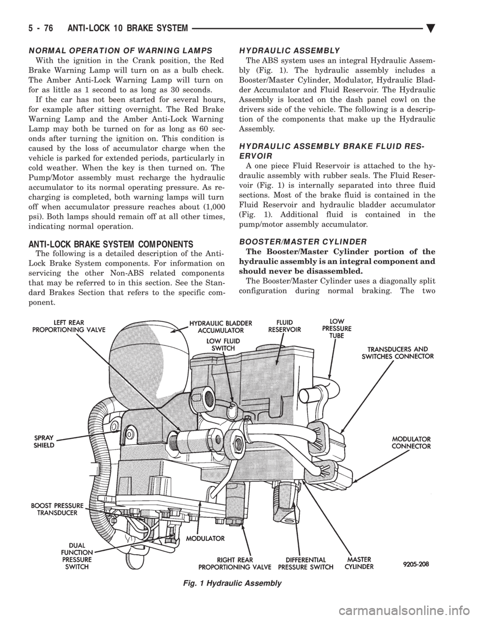
HYDRAULIC ASSEMBLY
The ABS system uses an integral Hydraulic Assem-
bly (Fig. 1). The hydraulic assembly includes a
Booster/Master Cylinder, Modulator, Hydraulic Blad-
der Accumulator and Fluid Reservoir. The Hydraulic
Assembly is located on the dash panel cowl on the
drivers side of the vehicle. The following is a descrip-
tion of the components that make up the Hydraulic
Assembly.
HYDRAULIC ASSEMBLY BRAKE FLUID RES- ERVOIR
A one piece Fluid Reservoir is attached to the hy-
draulic assembly with rubber seals. The Fluid Reser-
voir (Fig. 1) is internally separated into three fluid
sections. Most of the brake fluid is contained in the
Fluid Reservoir and hydraulic bladder accumulator
(Fig. 1). Additional fluid is contained in the
pump/motor assembly accumulator.
BOOSTER/MASTER CYLINDER
The Booster/Master Cylinder portion of the
hydraulic assembly is an integral component and
should never be disassembled. The Booster/Master Cylinder uses a diagonally split
configuration during normal braking. The two
Fig. 1 Hydraulic Assembly
5 - 76 ANTI-LOCK 10 BRAKE SYSTEM Ä
Page 266 of 2438
If the vehicle is not set in motion within 3 minutes
from the time the ignition switch is set in the on po-
sition. The solenoid test is bypassed but the pump/
motor is activated briefly to verify that it is
operating correctly.
WARNING SYSTEMS OPERATION
The ABS system uses an Amber Anti-Lock Warn-
ing Lamp, located in the instrument cluster. The
purpose of the warning lamp is discussed in detail
below. The Amber Anti-Lock Warning Light will turn on
when the (CAB) detects a condition which results in
a shutdown of the Anti-Lock function. The Amber
Anti-Lock Warning Lamp is normally on until the
(CAB) completes its self tests and turns the lamp off
(approximately 1-2 seconds). When the Amber Anti-
Lock Warning Light is on only the Anti-Lock func-
tion of the brake system if affected. The standard
brake system and the ability to stop the car will not
be affected when only the Amber Anti-Lock Warning
Light is on.
NORMAL OPERATION OF WARNING LAMP
With the ignition in the Crank position, the Red
Brake Warning Lamp will turn on as a bulb check.
The Amber Anti-Lock Warning Lamp will stay on for
1-2 seconds then turn off. Once verification of the self
diagnosis is completed.
ANTI-LOCK BRAKE SYSTEM COMPONENTS
The following is a detailed description of the Anti-
Lock Brake System components. For information on
servicing the Four Wheel Disk Brake System, see the
standard Brake section of this Service Manual.
MODULATOR ASSEMBLY
WARNING: THE ONLY PART OF THE MODULATOR
ASSEMBLY THAT IS A SERVICEABLE COMPONENT
IS THE DELTA P SWITCH. THE REMAINING COM-
PONENTS OF THE MODULATOR ASSEMBLY ARE
NOT SERVICEABLE ITEMS. NO ATTEMPT SHOULD
BE MADE TO REMOVE OR SERVICE ANY OTHER
PARTS OF THE MODULATOR ASSEMBLY.
The Modulator Assembly (Fig. 1) is located under
the battery tray and is covered with an acid shield.
The Modulator Assembly contains the following com-
ponents for controlling the Anti-Lock braking sys-
tem. 2 Isolation Valves, 4 Build/Decay Valves, 4
Shuttle Orifices, 2 Fluid Sumps, 2 Accumulators, a
Pump/Motor and a Pressure Differential Valve/
Switch. Also attached to the Modulator Assembly are
4 brake tubes which are connected to an 8 way con-
nector block. The connector block is mounted to the
left frame rail below the master cylinder in the same location as the non ABS equipped combination valve.
The wheel brake lines are attached to the system via
the connector block.
ISOLATION VALVES
The Isolation Valves are used to isolate the master
cylinder from the rest of the brake hydraulic circuit
during an Anti-Lock stop. Two Isolation Valves are
used, one for the primary circuit and one for the sec-
ondary circuit. The Isolation Valves are spring
loaded in the released position. In the released posi-
tion the Isolation Valves provide a fluid path from
the master cylinder outputs to the wheel brakes via
the Build/Decay valves. When actuated it provides a
fluid path from the accumulator (which was charged
by the Pump/Motor during ABS operation) to the
Build/Decay valves through the Shuttle Orifices.
BUILD/DECAY VALVES
There are 4 Build/Decay valves, one for each
wheel. In the released position they provide a fluid
path from the wheel brakes to the Isolation Valve
through the shuttle orifices. In the actuated (decay)
position, they provide a fluid path from the wheel
brakes to the sump. The Build/Decay valves are
spring loaded in the released (build) position.
SHUTTLE ORIFICE
There are 4 Shuttle Orifice Valves, one for each
wheel. The Shuttle Orifice Valve is a hydraulically
actuated valve which shuttles when the Build/Decay
valve is actuated. Actuating of the Build/Decay valve
causes a pressure differential to be created across the
Shuttle Orifice Valve. This acts like placing an ori-
fice (restriction) in the line between the Isolation
Valve and the Build/Decay Valve. This restriction
provides a controlled build rate to each wheel brake
during an Anti-Lock stop. The Shuttle Orifice Valve
will remain in the orificed position until the ABS cy-
cle is complete. When the ABS cycle has been com-
pleted the Isolation and Build/Decay valves will
return to their released position which will equalize
the pressure across the Shuttle Orifice Valves. When
the pressure equalizes, the spring loaded Shuttle Or-
ifice valves will return to the unrestricted position.
FLUID SUMPS
There are two Fluid Sumps in the Hydraulic As-
sembly, one each for the primary and secondary hy-
draulic circuits. The Fluid Sumps store the brake
fluid that is decayed from the wheel brakes during
ABS cycle. This fluid is then pumped to an accumu-
lator and/or the hydraulic system in order to provide
build pressure. The typical pressure in the sumps is
50 psi, During ABS operation only.
5 - 116 ANTI-LOCK 6 BRAKE SYSTEM Ä
Page 297 of 2438
The instrument panel bulb can be checked each
time the ignition switch is turned to the start posi-
tion or the parking brake is set.
HYDRAULIC SYSTEM SERVICE PROCEDURES
BRAKE WARNING SYSTEM
CHECKING BRAKE WARNING SWITCH UNIT
The Red Brake Warning light will come on when the
parking brake is applied with the ignition key turned
ON. The same light will also illuminate should one of
the two service brake hydraulic systems fail.
CAUTION:Make sure air does not enter the hydraulic
system during this test procedure. See bleeding with-
out a pressure bleeder at the beginning of this section
for master cylinder fluid level checking procedures.
To test the service brake warning system lamp.
Raise vehicle on a hoist and open a wheel cylinder
bleeder while a helper depresses the brake pedal and
observes the warning light.
If light fails to come on, inspect for a burned out bulb,
disconnected socket, or a broken or disconnected wire at
the switch. If the bulb is not burned out and the wire
continuity is not interrupted. Check the service brake
warning switch operation with a test lamp between the
switch terminal and a known good ground. Be sure to
fill master cylinder and bleed brake system after correc-
tion has been made, if necessary.
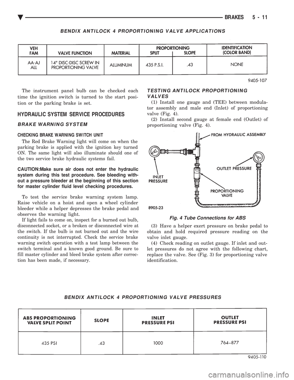
TESTING ANTILOCK PROPORTIONING VALVES
(1) Install one gauge and (TEE) between modula-
tor assembly and male end (Inlet) of proportioning
valve (Fig. 4). (2) Install second gauge at female end (Outlet) of
proportioning valve (Fig. 4).
(3) Have a helper exert pressure on brake pedal to
obtain and hold required pressure reading on the
valve inlet gauge. (4) Check reading on outlet gauge. If inlet and out-
let pressures do not agree with the following chart,
replace the valve. See (Fig. 3) for proportioning valve
identification.
BENDIX ANTILOCK 4 PROPORTIONING VALVE APPLICATIONS
BENDIX ANTILOCK 4 PROPORTIONING VALVE PRESSURES
Fig. 4 Tube Connections for ABS
Ä BRAKES 5 - 11
Page 302 of 2438
(2) The voltage output from each of the wheel
speed sensors is verified to be within the correct op-
erating range. If a vehicle is not set in motion within 3 minutes
from the time the ignition switch is turned to the on
position. The solenoid valve test is bypassed but the
pump/motor is activated briefly to verify that it is op-
erating correctly.
WARNING SYSTEMS OPERATION
The ABS system uses an Amber Antilock Warning
Lamp, located in the instrument cluster. The purpose
of the warning lamp is discussed in detail below. The Amber Antilock Warning Light will turn on
whenever the CAB detects a condition which results
in a shutdown of the Antilock brake system. The
Amber Antilock Warning Lamp is normally on until
the CAB completes its self tests and turns the lamp
off (approximately 1-2 seconds). When the Amber
Antilock Warning Light is on, only the Antilock
brake function of the brake system if affected. The
standard brake system and the ability to stop the car
will not be affected when only the Amber Antilock
Warning Light is on.
NORMAL OPERATION OF WARNING LAMP
With ignition key turned to the Crank position, the
Red Brake Warning Lamp and Amber Antilock
Warning Lamp will turn on as a bulb check. The
Amber Antilock Warning Lamp will stay on for 1-2
seconds then turn off, once verification of Antilock
Brake System self diagnosis is completed.
ANTILOCK BRAKE SYSTEM COMPONENTS
The following is a detailed description of the Ben-
dix Antilock 4 Brake System components. For infor-
mation on servicing the Four Wheel Disc Brake
System, see the standard Brake section in the Front
Wheel Drive Car, chassis service manual.
MODULATOR ASSEMBLY
WARNING: THE ONLY COMPONENTS OF THE
MODULATOR ASSSEMBLY THAT ARE SERVICE-
ABLE, ARE THE 2 PROPORTIONING VALVES,
BLEED SCREWS AND THREAD SAVERS. THE RE-
MAINING COMPONENTS OF THE MODULATOR AS-
SEMBLY ARE NOT INTENDED TO BE
SERVICEABLE ITEMS. NO ATTEMPT SHOULD BE
MADE TO REMOVE OR SERVICE ANY OTHER COM-
PONENTS OF THE MODEULATOR ASSEMBLY.
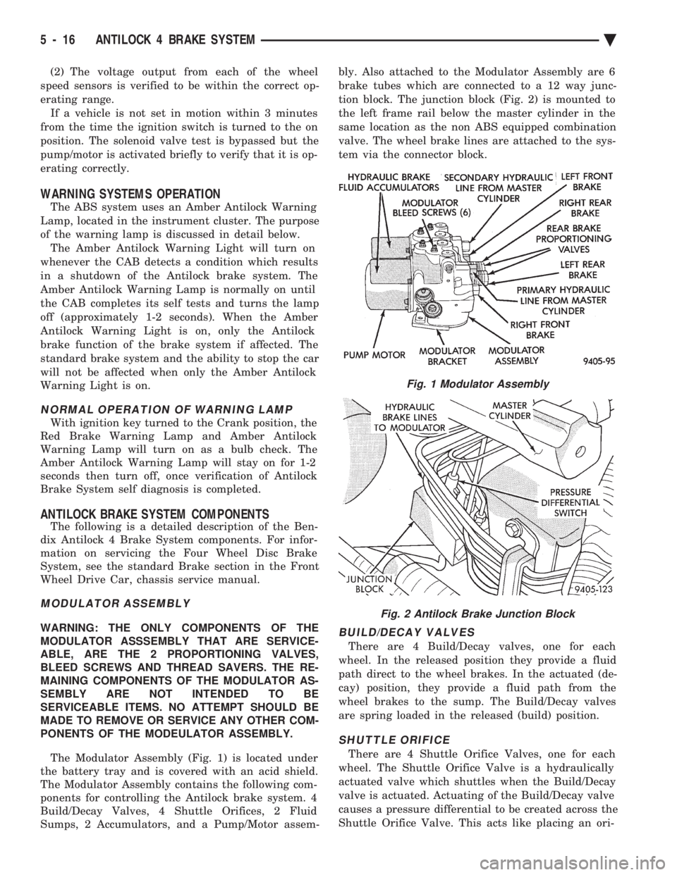
The Modulator Assembly (Fig. 1) is located under
the battery tray and is covered with an acid shield.
The Modulator Assembly contains the following com-
ponents for controlling the Antilock brake system. 4
Build/Decay Valves, 4 Shuttle Orifices, 2 Fluid
Sumps, 2 Accumulators, and a Pump/Motor assem- bly. Also attached to the Modulator Assembly are 6
brake tubes which are connected to a 12 way junc-
tion block. The junction block (Fig. 2) is mounted to
the left frame rail below the master cylinder in the
same location as the non ABS equipped combination
valve. The wheel brake lines are attached to the sys-
tem via the connector block.BUILD/DECAY VALVES
There are 4 Build/Decay valves, one for each
wheel. In the released position they provide a fluid
path direct to the wheel brakes. In the actuated (de-
cay) position, they provide a fluid path from the
wheel brakes to the sump. The Build/Decay valves
are spring loaded in the released (build) position.
SHUTTLE ORIFICE
There are 4 Shuttle Orifice Valves, one for each
wheel. The Shuttle Orifice Valve is a hydraulically
actuated valve which shuttles when the Build/Decay
valve is actuated. Actuating of the Build/Decay valve
causes a pressure differential to be created across the
Shuttle Orifice Valve. This acts like placing an ori-
Fig. 1 Modulator Assembly
Fig. 2 Antilock Brake Junction Block
5 - 16 ANTILOCK 4 BRAKE SYSTEM Ä
Page 381 of 2438
IGNITION OFF DRAW (IOD)
GENERAL INFORMATION
A normal electrical system will draw from 5 to 30
milliamperes from the battery. This is with the ignition
in the OFF position, and all non-ignition controlled cir-
cuits in proper working order. The amount of IOD will
depend on body model and electrical components. A ve-
hicle that has not been operated for an extended period
of approximately 20 days may discharge the battery to
an inadequate level. In this case, the Main Fusible Link
Connector should be disconnected. The Main Fusible
Link connector is located rearward of the battery on the
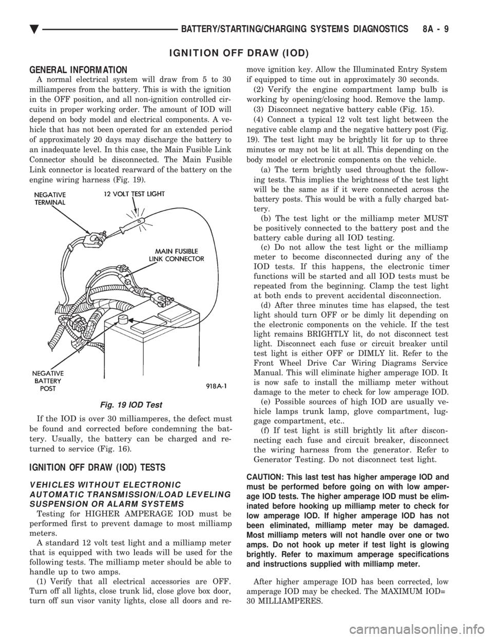
engine wiring harness (Fig. 19).
If the IOD is over 30 milliamperes, the defect must
be found and corrected before condemning the bat-
tery. Usually, the battery can be charged and re-
turned to service (Fig. 16).
IGNITION OFF DRAW (IOD) TESTS
VEHICLES WITHOUT ELECTRONIC AUTOMATIC TRANSMISSION/LOAD LEVELINGSUSPENSION OR ALARM SYSTEMS
Testing for HIGHER AMPERAGE IOD must be
performed first to prevent damage to most milliamp
meters. A standard 12 volt test light and a milliamp meter
that is equipped with two leads will be used for the
following tests. The milliamp meter should be able to
handle up to two amps.
(1) Verify that all electrical accessories are OFF.
Turn off all lights, close trunk lid, close glove box door,
turn off sun visor vanity lights, close all doors and re- move ignition key. Allow the Illuminated Entry System
if equipped to time out in approximately 30 seconds.
(2) Verify the engine compartment lamp bulb is
working by opening/closing hood. Remove the lamp. (3) Disconnect negative battery cable (Fig. 15).
(4) Connect a typical 12 volt test light between the
negative cable clamp and the negative battery post (Fig.
19). The test light may be brightly lit for up to three
minutes or may not be lit at all. This depending on the
body model or electronic components on the vehicle. (a) The term brightly used throughout the follow-
ing tests. This implies the brightness of the test light
will be the same as if it were connected across the
battery posts. This would be with a fully charged bat-
tery.
(b) The test light or the milliamp meter MUST
be positively connected to the battery post and the
battery cable during all IOD testing. (c) Do not allow the test light or the milliamp
meter to become disconnected during any of the
IOD tests. If this happens, the electronic timer
functions will be started and all IOD tests must be
repeated from the beginning. Clamp the test light
at both ends to prevent accidental disconnection.
(d) After three minutes time has elapsed, the test
light should turn OFF or be dimly lit depending on
the electronic components on the vehicle. If the test
light remains BRIGHTLY lit, do not disconnect test
light. Disconnect each fuse or circuit breaker until
test light is either OFF or DIMLY lit. Refer to the
Front Wheel Drive Car Wiring Diagrams Service
Manual. This will eliminate higher amperage IOD. It
is now safe to install the milliamp meter without
damage to the meter to check for low amperage IOD.
(e) Possible sources of high IOD are usually ve-
hicle lamps trunk lamp, glove compartment, lug-
gage compartment, etc.. (f) If test light is still brightly lit after discon-
necting each fuse and circuit breaker, disconnect
the wiring harness from the generator. Refer to
Generator Testing. Do not disconnect test light.
CAUTION: This last test has higher amperage IOD and
must be performed before going on with low amper-
age IOD tests. The higher amperage IOD must be elim-
inated before hooking up milliamp meter to check for
low amperage IOD. If higher amperage IOD has not
been eliminated, milliamp meter may be damaged.
Most milliamp meters will not handle over one or two
amps. Do not hook up meter if test light is glowing
brightly. Refer to maximum amperage specifications
and instructions supplied with milliamp meter.
After higher amperage IOD has been corrected, low
amperage IOD may be checked. The MAXIMUM IOD=
30 MILLIAMPERES.
Fig. 19 IOD Test
Ä BATTERY/STARTING/CHARGING SYSTEMS DIAGNOSTICS 8A - 9
Page 549 of 2438
(11) Remove two screws from fuse block and lower
fuse block. (12) Remove three screws from hood release and
lower hood release handle. (13) Remove flasher relay from bracket on center
distribution duct. (14) Remove screw from ATC sensor motor assem-
bly and unhook from bracket if equipped. (15) Remove the radio ground screw above flasher
relay mount. (16) Remove center distribution duct screw from
left instrument panel lower brace, then remove four
screws to remove left lower brace.
(17) Remove five nuts on steering column and drop
column, then remove two upper column attaching studs.
(18) Remove two screws and pull out compact disc
player or cubby box, disconnect Co-Axial cable from
compact disc player. (19) Remove Electronic Vehicle Information Center
(E.V.I.C.) or Traveler from vehicle. (20) Remove radio.
(21) Remove A.T.C., A/C or heater controls. (22) Squeeze latches on side of Rear Window defog-
ger switch and remove. (23) Snap off cluster lower trim bezel, switch pod
vent grille, speaker grilles and defroster grilles. (24) Remove switch pod assembly.
(25) Remove cluster assembly.
(26) Remove dash speakers.
(27) Snap out bezel with or without message center
and disconnect wiring. (28) Open glovebox door, squeeze sides and roll
glovebox completely open. Remove glovebox light
switch, and disconnect wires. (29) Loosen right cowl side pivot bolt through
glovebox opening then close glovebox. (30) Loosen left cowl side pivot.
(31) Remove four screw attachments at top of in-
strument panel and roll panel out. (32) Pull wiring, antenna cable, A/C cable and vac-
uum lines out of instrument panel. Disconnect demis-
ter hose and remove instrument panel with ducts
attached. (33) Transfer ducts and brackets onto new panel.
(34) For instrument panel roll up, reverse
above procedures.
INTERIOR LAMP REMOVAL
The Dome, Floor Console and Door Lamps operate
when the doors are open or headlamp switch is
placed in courtesy position.
DOME LAMP
(1) Pry either the forward or rearward edge of the
dome lamp to free it from retaining bracket. (2) Pry either the forward or rearward edge of the
lens away from the bezel and replace lamp. (3) For installation reverse above procedures.
FRONT HEADER READING LAMP
Pull lamp from headliner. Disconnect wiring and
replace lamp.
FLOOR CONSOLE LAMP
Pry along top edge of lamp and pivot lamp out of
floor console, the lens does not remove. Remove lamp
and twist out lamp socket. Replace lamp.
DOOR LAMPS
Pry along bottom edge of lamp and pivot lamp out
of door trim panel, the lens does not remove. Remove
lamp and twist out lamp socket. Replace lamp.
DOOR REFLECTORS
Pry reflector away from the door trim panel, and
replace.
TRUNK LAMP
Remove lens by prying lens out of trunk trim panel
and replace bulb.
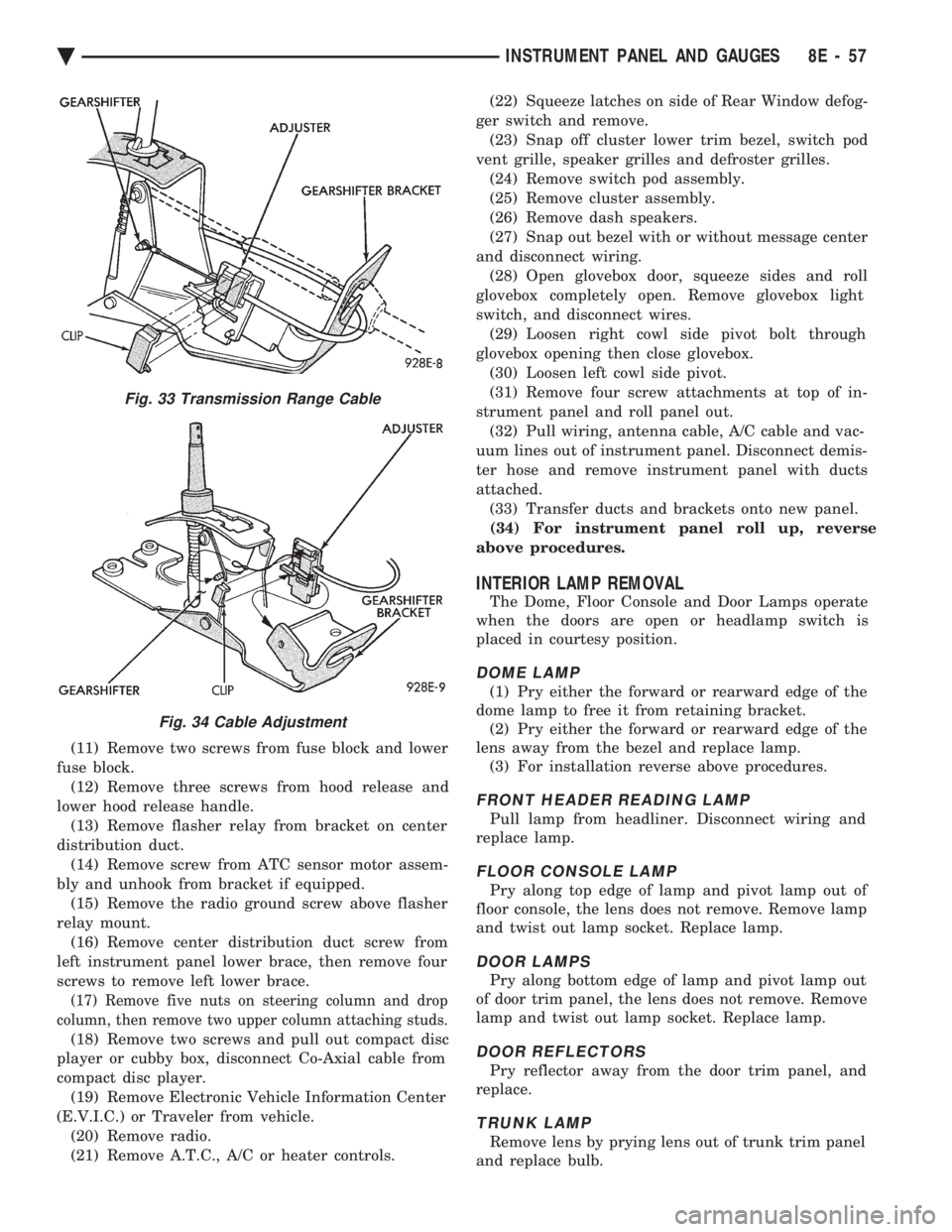
Fig. 33 Transmission Range Cable
Fig. 34 Cable Adjustment
Ä INSTRUMENT PANEL AND GAUGES 8E - 57