check oil CHEVROLET PLYMOUTH ACCLAIM 1993 Service Manual
[x] Cancel search | Manufacturer: CHEVROLET, Model Year: 1993, Model line: PLYMOUTH ACCLAIM, Model: CHEVROLET PLYMOUTH ACCLAIM 1993Pages: 2438, PDF Size: 74.98 MB
Page 44 of 2438
ENGINE INDEX
page page
Engine Oil Filter .......................... 9
Battery ................................ 15
Crankcase Ventilation System ............... 13
Drive Belts ............................. 14
Emission Control System ................... 14
Engine Air Cleaner ....................... 11
Engine Cooling System .................... 10 Engine Oil
............................... 8
Frequency of Engine Oil and Filter Changes ..... 8
Fuel Filter .............................. 14
Fuel Recommendations .................... 14
Ignition Cables, Distributor Cap, and Rotor ..... 14
Rubber and Plastic Component Inspection ...... 15
Spark Plugs ............................ 14
FREQUENCY OF ENGINE OIL AND FILTER
CHANGES
ENGINE OIL
Road conditions as well as your kind of driving af-
fect the interval at which your oil should be changed.
Check the following to determine if any apply to you:
² Frequent short trip driving less than 8 kilometers
(5 miles)
² Frequent driving in dusty conditions
² Frequent trailer towing
² Extensive idling (such as vehicle operation in stop
and go traffic)
² More than 50% of your driving is at sustained
high speeds during hot weather, above 32ÉC (90ÉF) If any of these apply to you then change your en-
gine oil every 4 800 kilometers (3,000 miles) or 3
months, whichever comes first. If none of these apply to you then change your oil
every 12 000 kilometers (7,500 miles) or 6 months,
whichever comes first. If none of these apply and the vehicle is in com-
mercial type service such as, Police, Taxi or Limou-
sine and principally used for highway driving of 40
kilometers (25 miles) or more between stations, the
engine oil should be changed every 8 000 kilometers
(5,000 miles) or 6 months, whichever comes first.
FLEXIBLE FUEL VEHICLES
Flexible fuel is corrosive and contributes to engine
oil contamination. When flexible fuel is being used,
the engine oil should be changed every 8 000 kilome-
ters (5,000 miles) or 6 months, whichever comes first.
OIL FILTER
The engine oil filter should be replaced with a new
filter at every second oil change.
ENGINE OIL
WARNING: NEW OR USED ENGINE OIL CAN BE IR-
RITATING TO THE SKIN. AVOID PROLONGED OR
REPEATED SKIN CONTACT WITH ENGINE OIL.
CONTAMINANTS IN USED ENGINE OIL, CAUSED
BY INTERNAL COMBUSTION, CAN BE HAZARDOUS TO YOUR HEALTH. THOROUGHLY WASH EX-
POSED SKIN WITH SOAP AND WATER. DO NOT WASH SKIN WITH GASOLINE, DIESEL
FUEL, THINNER, OR SOLVENTS, HEALTH PROB-
LEMS CAN RESULT. DO NOT POLLUTE, DISPOSE OF USED ENGINE
OIL PROPERLY. CONTACT YOUR DEALER OR
GOVERNMENT AGENCY FOR LOCATION OF COL-
LECTION CENTER IN YOUR AREA.
BREAK-IN PERIOD
CAUTION: Wide open throttle operation in low
gears, before engine break-in period is complete,
can damage engine.
On a Chrysler Corporation vehicle an extended
break-in period is not required. Driving speeds of not
over 80-90 km/h (50-55 mph) for the first 100 km (60
miles) is recommended. Hard acceleration and high
engine rpm in lower gears should be avoided.
SELECTING ENGINE OIL
CAUTION: Do not use non-detergent or straight
mineral oil when adding or changing crankcase lu-
bricant. Engine or Turbocharger failure can result.
The factory fill engine oil is a high quality, energy
conserving, crankcase lubricant. The Recommended
SAE Viscosity Grades chart defines the viscosity
grades that must be used based on temperature in
the region where vehicle is operated and optional
equipment.
NON-FLEXIBLE FUEL VEHICLES Chrysler Corporation recommends that Mopar mo-
tor oil, or equivalent, be used when adding or chang-
ing crankcase lubricant. The API symbol (Fig. 1) on
the container indicates the viscosity grade, quality
and fuel economy ratings of the lubricant it contains.
Use ENERGY CONSERVING II motor oil with API
SERVICE SG or SG/CD classification.
0 - 8 LUBRICATION AND MAINTENANCE Ä
Page 58 of 2438
BRAKE RESERVOIR LEVEL INSPECTION
WARNING: DO NOT ALLOW PETROLEUM OR WATER
BASE LIQUIDS TO CONTAMINATE BRAKE FLUID,
SEAL DAMAGE AND BRAKE FAILURE CAN RESULT.
RELIEVE PRESSURE IN ANTI-LOCK BRAKE SYS-
TEM BEFORE ADDING BRAKE FLUID TO RESER-
VOIR. IF NOT, BRAKE FLUID COULD DISCHARGED
FROM THE RESERVOIR POSSIBLY CAUSING PER-
SONAL INJURY.
The brake reservoir level should be inspected when
other under hood service is performed. It is normal
for the reservoir level to drop as disc brake pads
wear. When fluid must be added, use Mopar, Brake
Fluid or equivalent. Use only brake fluid conforming
to DOT 3, Federal, Department of Transportation
specification. To avoid brake fluid contamination, use
fluid from a properly sealed container. On vehicles with anti-lock brakes, depressurize the
system before inspecting fluid level. Turn OFF the
ignition and remove the key. Pump the brake pedal
at least 50 times to relieve the pressure in the sys-
tem.
On all vehicles, if fluid should become low after sev-
eral thousand kilometers (miles), fill the reservoir to
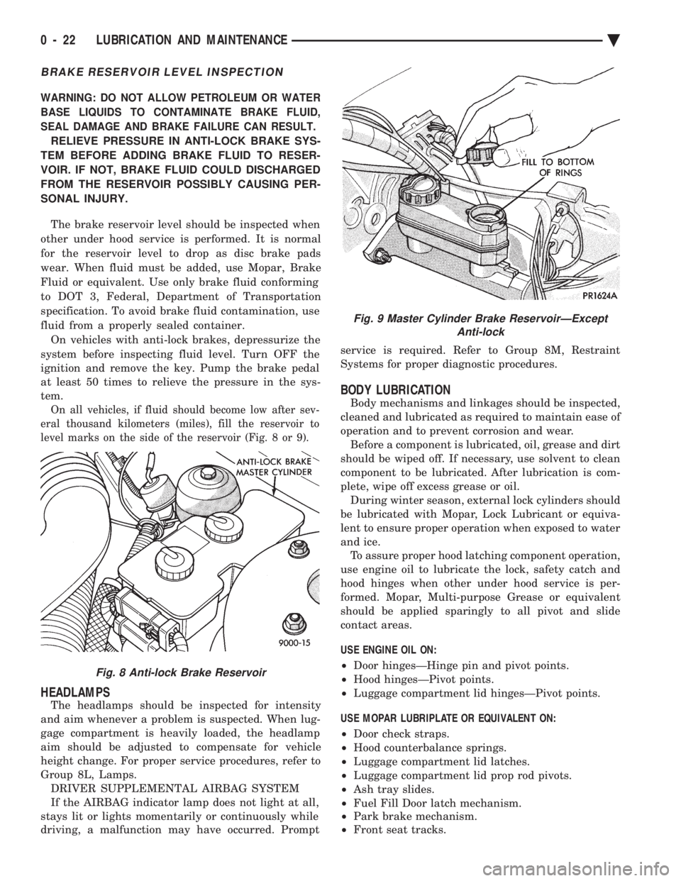
level marks on the side of the reservoir (Fig. 8 or 9).
HEADLAMPS
The headlamps should be inspected for intensity
and aim whenever a problem is suspected. When lug-
gage compartment is heavily loaded, the headlamp
aim should be adjusted to compensate for vehicle
height change. For proper service procedures, refer to
Group 8L, Lamps. DRIVER SUPPLEMENTAL AIRBAG SYSTEM
If the AIRBAG indicator lamp does not light at all,
stays lit or lights momentarily or continuously while
driving, a malfunction may have occurred. Prompt service is required. Refer to Group 8M, Restraint
Systems for proper diagnostic procedures.
BODY LUBRICATION
Body mechanisms and linkages should be inspected,
cleaned and lubricated as required to maintain ease of
operation and to prevent corrosion and wear. Before a component is lubricated, oil, grease and dirt
should be wiped off. If necessary, use solvent to clean
component to be lubricated. After lubrication is com-
plete, wipe off excess grease or oil. During winter season, external lock cylinders should
be lubricated with Mopar, Lock Lubricant or equiva-
lent to ensure proper operation when exposed to water
and ice. To assure proper hood latching component operation,
use engine oil to lubricate the lock, safety catch and
hood hinges when other under hood service is per-
formed. Mopar, Multi-purpose Grease or equivalent
should be applied sparingly to all pivot and slide
contact areas.
USE ENGINE OIL ON:
² Door hingesÐHinge pin and pivot points.
² Hood hingesÐPivot points.
² Luggage compartment lid hingesÐPivot points.
USE MOPAR LUBRIPLATE OR EQUIVALENT ON:
² Door check straps.
² Hood counterbalance springs.
² Luggage compartment lid latches.
² Luggage compartment lid prop rod pivots.
² Ash tray slides.
² Fuel Fill Door latch mechanism.
² Park brake mechanism.
² Front seat tracks.
Fig. 8 Anti-lock Brake Reservoir
Fig. 9 Master Cylinder Brake ReservoirÐExcept
Anti-lock
0 - 22 LUBRICATION AND MAINTENANCE Ä
Page 63 of 2438
FRONT SUSPENSION SERVICE PROCEDURES INDEX
page page
Ball Joints .............................. 13
Hub and Bearing Assembly ................. 20
Knuckle (Front Suspension) ................. 16
Lower Control Arm ....................... 10
Lower Control Arm Pivot Bushings ........... 11 Shock Absorbers (Strut Damper)
............. 10
Strut Damper Assembly ..................... 7
Suspension Coil Springs .................... 9
Sway Bar .............................. 14
Wheel Alignment .......................... 5
WHEEL ALIGNMENT
Front wheel alignment is the proper adjustment of
all interrelated front suspension angles. These angles
are what affects the running and steering of the
front wheels of the vehicle. The method of checking front alignment will vary
depending on the type of equipment being used. The
instructions furnished by the manufacturer of the
equipment should always be followed. With the ex-
ception that the alignment specifications recom-
mended by Chrysler Corporation be used. There are six basic factors which are the founda-
tion to front wheel alignment. These are height,
caster, camber, toe-in, steering axis inclination and
toe-out on turns. Of the six basic factors only camber
and toe in are mechanically adjustable (Fig. 1)
CAUTION: Do not attempt to modify any suspen-
sion or steering components by heating or bending
of the component.
Wheel alignment adjustments and checks should be
made in the following sequence. (1) Camber
(2) Toe
Camber is the number of degrees the top of the
wheel is tilted inward or outward from true vertical.
Inward tilt is negative camber. Outward tilt is posi-
tive camber. Excessive camber is a tire wear factor: negative
camber causes wear on the inside of the tire, while
positive camber causes wear to the outside. Toe
is measured in degrees or inches and is the
distance the front edges of the tires are closer (or far-
ther apart) than the rear edges. See Front Wheel
Drive Specifications for Toesettings.
PRE-ALIGNMENT
Before any attempt is made to change or correct
the wheel alignment factors. The following inspection
and necessary corrections must be made on those
parts which influence the steering of the vehicle. (1) Check and inflate tires to recommended pres-
sure. All tires should be the same size and in good
condition and have approximately the same wear.
Note type of tread wear which will aid in diagnosing,
see Wheels and Tires, Group 22. (2) Check front wheel and tire assembly for radial
runout. (3) Inspect lower ball joints and all steering link-
age for looseness. (4) Check for broken or sagged front and rear
springs. Front suspension must only be checked after the
vehicle has had the following checked or adjusted.
Tires set to recommended pressures, full tank of fuel,
no passenger or luggage compartment load and is on
a level floor or alignment rack. Just prior to each alignment reading. The vehicle
should be bounced (rear first, then front) by grasping
bumper at center and jouncing each end an equal
number of times. Always release bumpers at bottom
of down cycle.
Ä SUSPENSION AND DRIVESHAFTS 2 - 5
Page 66 of 2438
INSPECTION
Inspect for evidence of fluid running from the up-
per end of the reservoir. (Actual leakage will be a
stream of fluid running down the side and dripping
off lower end of unit). A slight amount of seepage be-
tween the strut rod and strut shaft seal is not un-
usual and does not affect performance of the strut
assembly.
INSTALLATION
(1) Install unit into fender reinforcement and in-
stall retaining nuts and washer assemblies (Fig. 1).
Tighten the 3 nuts to 27 N Im (20 ft. lbs.) torque.
(2) Position steering knuckle neck into strut as-
sembly. Position washer plate and install cam and
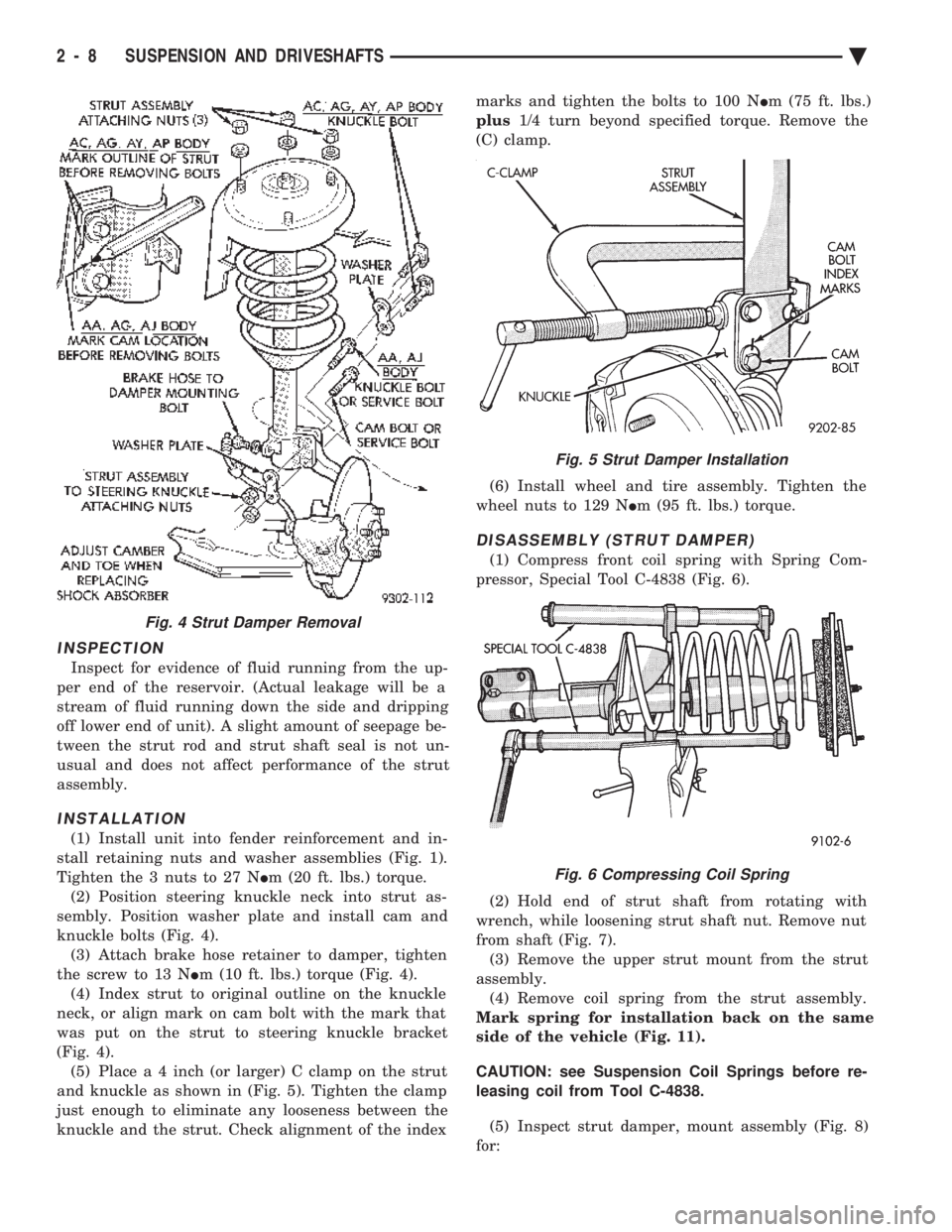
knuckle bolts (Fig. 4). (3) Attach brake hose retainer to damper, tighten
the screw to 13 N Im (10 ft. lbs.) torque (Fig. 4).
(4) Index strut to original outline on the knuckle
neck, or align mark on cam bolt with the mark that
was put on the strut to steering knuckle bracket
(Fig. 4). (5) Plac e a 4 inch (or larger) C clamp on the strut
and knuckle as shown in (Fig. 5). Tighten the clamp
just enough to eliminate any looseness between the
knuckle and the strut. Check alignment of the index marks and tighten the bolts to 100 N
Im (75 ft. lbs.)
plus 1/4 turn beyond specified torque. Remove the
(C) clamp.
(6) Install wheel and tire assembly. Tighten the
wheel nuts to 129 N Im (95 ft. lbs.) torque.
DISASSEMBLY (STRUT DAMPER)
(1) Compress front coil spring with Spring Com-
pressor, Special Tool C-4838 (Fig. 6).
(2) Hold end of strut shaft from rotating with
wrench, while loosening strut shaft nut. Remove nut
from shaft (Fig. 7). (3) Remove the upper strut mount from the strut
assembly. (4) Remove coil spring from the strut assembly.
Mark spring for installation back on the same
side of the vehicle (Fig. 11).
CAUTION: see Suspension Coil Springs before re-
leasing coil from Tool C-4838.
(5) Inspect strut damper, mount assembly (Fig. 8)
for:
Fig. 4 Strut Damper Removal
Fig. 5 Strut Damper Installation
Fig. 6 Compressing Coil Spring
2 - 8 SUSPENSION AND DRIVESHAFTS Ä
Page 97 of 2438
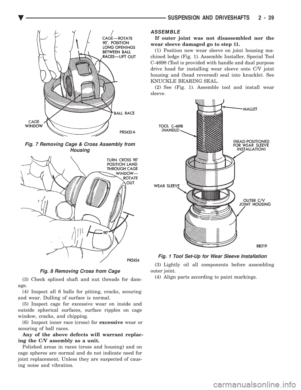
(3) Check splined shaft and nut threads for dam-
age. (4) Inspect all 6 balls for pitting, cracks, scouring
and wear. Dulling of surface is normal. (5) Inspect cage for excessive wear on inside and
outside spherical surfaces, surface ripples on cage
window, cracks, and chipping. (6) Inspect inner race (cross) for excessivewear or
scouring of ball races. Any of the above defects will warrant replac-
ing the C/V assembly as a unit. Polished areas in races (cross and housing) and on
cage spheres are normal and do not indicate need for
joint replacement. Unless they are suspected of caus-
ing noise and vibration.
ASSEMBLE
If outer joint was not disassembled nor the
wear sleeve damaged go to step 11. (1) Position new wear sleeve on joint housing ma-
chined ledge (Fig. 1). Assemble Installer, Special Tool
C-4698 (Tool is provided with handle and dual purpose
drive head for installing wear sleeve onto C/V joint
housing and (head reversed) seal into knuckle). See
KNUCKLE BEARING SEAL. (2) See (Fig. 1). Assemble tool and install wear
sleeve.
(3) Lightly oil all components before assembling
outer joint. (4) Align parts according to paint markings.
Fig. 7 Removing Cage & Cross Assembly from Housing
Fig. 8 Removing Cross from Cage
Fig. 1 Tool Set-Up for Wear Sleeve Installation
Ä SUSPENSION AND DRIVESHAFTS 2 - 39
Page 99 of 2438
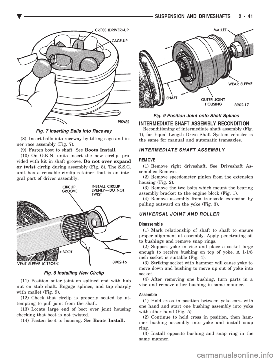
(8) Insert balls into raceway by tilting cage and in-
ner race assembly (Fig. 7). (9) Fasten boot to shaft. See Boots Install.
(10) On G.K.N. units insert the new circlip, pro-
vided with kit in shaft groove. Do not over expand
or twist circlip during assembly (Fig. 8). The S.S.G.
unit has a reusable circlip retainer that is an inte-
gral part of driver assembly.
(11) Position outer joint on splined end with hub
nut on stub shaft. Engage splines, and tap sharply
with mallet (Fig. 9). (12) Check that circlip is properly seated by at-
tempting to pull joint from the shaft. (13) Locate large end of boot over joint housing
checking that boot is not twisted. (14) Fasten boot to housing. See Boots Install.
INTERMEDIATE SHAFT ASSEMBLY RECONDITION
Reconditioning of intermediate shaft assembly (Fig.
1), for Equal Length Drive Shaft System vehicles is
the same for manual and automatic transaxles.
INTERMEDIATE SHAFT ASSEMBLY
REMOVE
(1) Remove right driveshaft. See Driveshaft As-
semblies Remove. (2) Remove speedometer pinion from the extension
housing (Fig. 2). (3) Remove the two bolts which mount the bearing
assembly bracket to the engine block (Fig. 1). (4) Remove assembly from transaxle extension by
pulling outward on the yoke (Fig. 3).
UNIVERSAL JOINT AND ROLLER
Disassemble
(1) Mark relationship of shaft to shaft to ensure
proper alignment at assembly. Apply penetrating oil
to bushings and remove snap rings. (2) Support yoke in vise and place a socket large
enough to receive bushing on top of yoke. A 1-1/8
inch socket is suitable (Fig. 4). (3) Striking socket with hammer will cause yoke to
move down and bushing to move up out of yoke into
socket. (4) After removing one bushing, turn parts in a
vise and remove other bushing in same manner.
Assemble (1) Hold cross in position between yoke ears with
one hand and start one bushing assembly into yoke
with other hand (Fig. 5). (2) Continue to hold cross in position, then ham-
mer bushing assembly into yoke and install snap
ring. (3) Install opposite bushing and snap ring in the
same manner.
Fig. 7 Inserting Balls into Raceway
Fig. 8 Installing New Circlip
Fig. 9 Position Joint onto Shaft Splines
Ä SUSPENSION AND DRIVESHAFTS 2 - 41
Page 154 of 2438
SERVICE ADJUSTMENTS INDEX
page page
Adjusting Rear Service Brakes ............... 4
Bleeding Brake System ..................... 6
Brake Hose and Tubing ................... 11
Master Cylinder Fluid Level .................. 4 Stop Lamp Switch Adjustment (All Vehicles)
.... 13
Test for Fluid Contamination ................. 7
Testing Application Adjuster Operation ......... 6
Wheel Stud Nut Tightening .................. 7
MASTER CYLINDER FLUID LEVEL
ALL EXCEPT AC/AY BODY WITH ABS
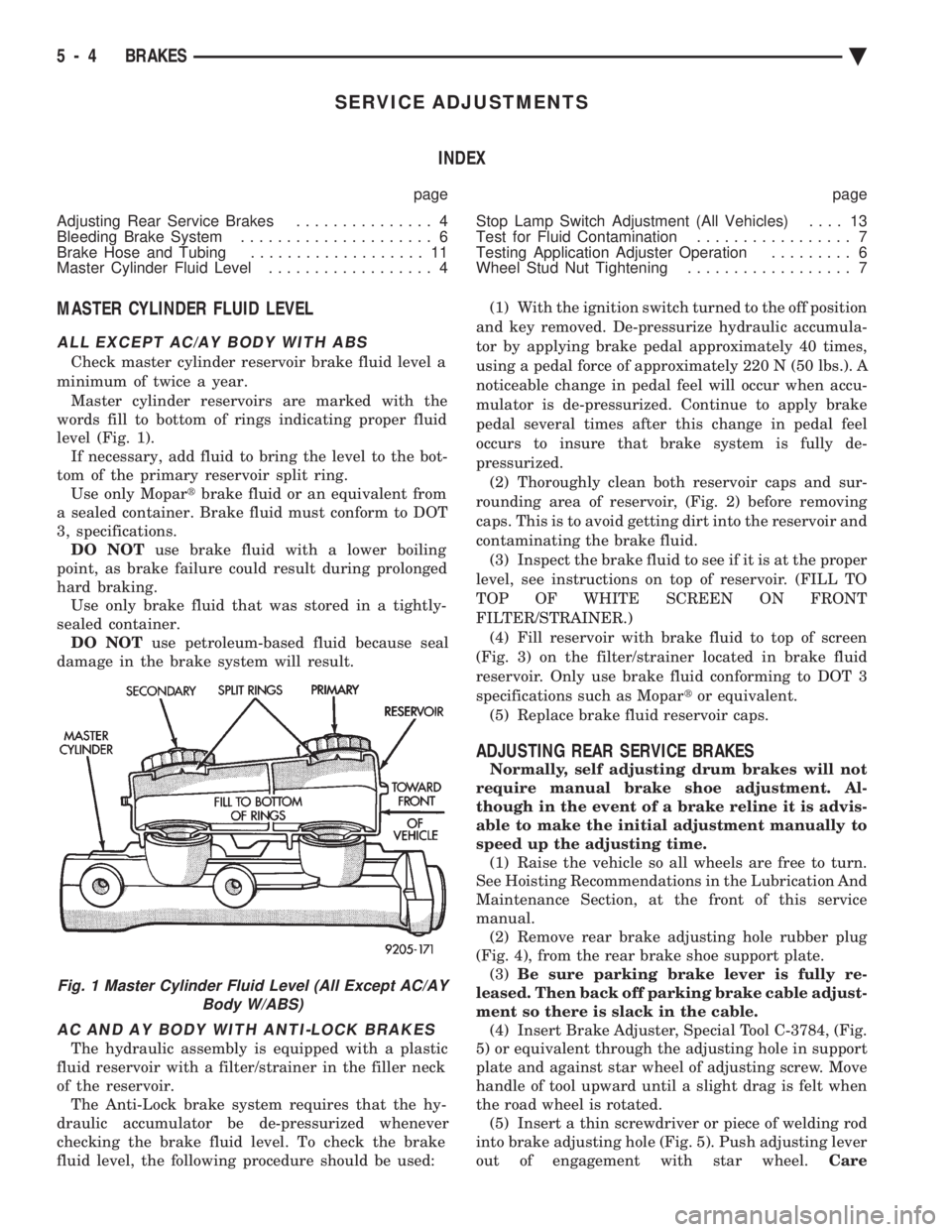
Check master cylinder reservoir brake fluid level a
minimum of twice a year. Master cylinder reservoirs are marked with the
words fill to bottom of rings indicating proper fluid
level (Fig. 1). If necessary, add fluid to bring the level to the bot-
tom of the primary reservoir split ring. Use only Mopar tbrake fluid or an equivalent from
a sealed container. Brake fluid must conform to DOT
3, specifications. DO NOT use brake fluid with a lower boiling
point, as brake failure could result during prolonged
hard braking. Use only brake fluid that was stored in a tightly-
sealed container. DO NOT use petroleum-based fluid because seal
damage in the brake system will result.
AC AND AY BODY WITH ANTI-LOCK BRAKES
The hydraulic assembly is equipped with a plastic
fluid reservoir with a filter/strainer in the filler neck
of the reservoir. The Anti-Lock brake system requires that the hy-
draulic accumulator be de-pressurized whenever
checking the brake fluid level. To check the brake
fluid level, the following procedure should be used: (1) With the ignition switch turned to the off position
and key removed. De-pressurize hydraulic accumula-
tor by applying brake pedal approximately 40 times,
using a pedal force of approximately 220 N (50 lbs.). A
noticeable change in pedal feel will occur when accu-
mulator is de-pressurized. Continue to apply brake
pedal several times after this change in pedal feel
occurs to insure that brake system is fully de-
pressurized. (2) Thoroughly clean both reservoir caps and sur-
rounding area of reservoir, (Fig. 2) before removing
caps. This is to avoid getting dirt into the reservoir and
contaminating the brake fluid. (3) Inspect the brake fluid to see if it is at the proper
level, see instructions on top of reservoir. (FILL TO
TOP OF WHITE SCREEN ON FRONT
FILTER/STRAINER.) (4) Fill reservoir with brake fluid to top of screen
(Fig. 3) on the filter/strainer located in brake fluid
reservoir. Only use brake fluid conforming to DOT 3
specifications such as Mopar tor equivalent.
(5) Replace brake fluid reservoir caps.
ADJUSTING REAR SERVICE BRAKES
Normally, self adjusting drum brakes will not
require manual brake shoe adjustment. Al-
though in the event of a brake reline it is advis-
able to make the initial adjustment manually to
speed up the adjusting time. (1) Raise the vehicle so all wheels are free to turn.
See Hoisting Recommendations in the Lubrication And
Maintenance Section, at the front of this service
manual. (2) Remove rear brake adjusting hole rubber plug
(Fig. 4), from the rear brake shoe support plate. (3) Be sure parking brake lever is fully re-
leased. Then back off parking brake cable adjust-
ment so there is slack in the cable. (4) Insert Brake Adjuster, Special Tool C-3784, (Fig.
5) or equivalent through the adjusting hole in support
plate and against star wheel of adjusting screw. Move
handle of tool upward until a slight drag is felt when
the road wheel is rotated. (5) Insert a thin screwdriver or piece of welding rod
into brake adjusting hole (Fig. 5). Push adjusting lever
out of engagement with star wheel. Care
Fig. 1 Master Cylinder Fluid Level (All Except AC/AY
Body W/ABS)
5 - 4 BRAKES Ä
Page 220 of 2438
(7) Unfasten brackets on steel heater water line at
dash panel and left frame rail. On Manual Transmis-
sion vehicles, unfasten clutch cable bracket at shock
tower and move aside. (8) Slide the power brake unit up and to the left
(mounting holes are slotted) on the dash panel, then
tilt inboard and up to remove.
CAUTION: Do not attempt to disassemble power
brake unit as this booster is serviced ONLY as a
complete assembly.
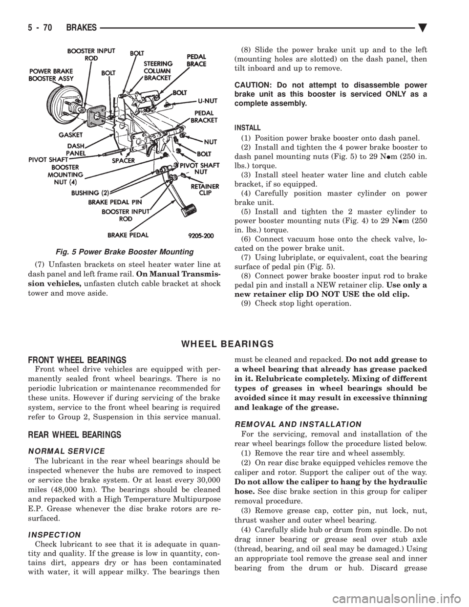
INSTALL (1) Position power brake booster onto dash panel.
(2) Install and tighten the 4 power brake booster to
dash panel mounting nuts (Fig. 5) to 29 N Im (250 in.
lbs.) torque. (3) Install steel heater water line and clutch cable
bracket, if so equipped. (4) Carefully position master cylinder on power
brake unit. (5) Install and tighten the 2 master cylinder to
power booster mounting nuts (Fig. 4) to 29 N Im (250
in. lbs.) torque. (6) Connect vacuum hose onto the check valve, lo-
cated on the power brake unit. (7) Using lubriplate, or equivalent, coat the bearing
surface of pedal pin (Fig. 5). (8) Connect power brake booster input rod to brake
pedal pin and install a NEW retainer clip. Use only a
new retainer clip DO NOT USE the old clip. (9) Check stop light operation.
WHEEL BEARINGS
FRONT WHEEL BEARINGS
Front wheel drive vehicles are equipped with per-
manently sealed front wheel bearings. There is no
periodic lubrication or maintenance recommended for
these units. However if during servicing of the brake
system, service to the front wheel bearing is required
refer to Group 2, Suspension in this service manual.
REAR WHEEL BEARINGS
NORMAL SERVICE
The lubricant in the rear wheel bearings should be
inspected whenever the hubs are removed to inspect
or service the brake system. Or at least every 30,000
miles (48,000 km). The bearings should be cleaned
and repacked with a High Temperature Multipurpose
E.P. Grease whenever the disc brake rotors are re-
surfaced.
INSPECTION
Check lubricant to see that it is adequate in quan-
tity and quality. If the grease is low in quantity, con-
tains dirt, appears dry or has been contaminated
with water, it will appear milky. The bearings then must be cleaned and repacked.
Do not add grease to
a wheel bearing that already has grease packed
in it. Relubricate completely. Mixing of different
types of greases in wheel bearings should be
avoided since it may result in excessive thinning
and leakage of the grease.
REMOVAL AND INSTALLATION
For the servicing, removal and installation of the
rear wheel bearings follow the procedure listed below. (1) Remove the rear tire and wheel assembly.
(2) On rear disc brake equipped vehicles remove the
caliper and rotor. Support the caliper out of the way.
Do not allow the caliper to hang by the hydraulic
hose. See disc brake section in this group for caliper
removal procedure. (3) Remove grease cap, cotter pin, nut lock, nut,
thrust washer and outer wheel bearing. (4) Carefully slide hub or drum from spindle. Do not
drag inner bearing or grease seal over stub axle
(thread, bearing, and oil seal may be damaged.) Using
an appropriate tool remove the grease seal and inner
bearing from the drum or hub. Discard grease
Fig. 5 Power Brake Booster Mounting
5 - 70 BRAKES Ä
Page 243 of 2438
DRIVE-OFF CYCLE
The DRIVE-OFF CYCLE takes place when the ve-
hicle reaches about 3 miles per hour the first time af-
ter an ignition reset. During this test, the modulator
solenoid valves are activated briefly to test their
function. The DRIVE-OFF CYCLE will be bypassed
if you drive-off with the service brake pedal de-
pressed.
LATCHING VERSUS NON-LATCHING FAULTS
Some faults detected by the (CAB) are latching.
The fault is latched and (ABS) function is disabled
until the ignition switch is reset (turned OFF/ON).
Thus (ABS) function is disabled even if the original
fault has disappeared during the ignition cycle in
which it occurred. Other faults are non-latching; any
warning lights that are turned on are only on as long
as the fault condition exists. As soon as the condition
goes away. The Amber Anti-Lock Warning Light is
turned off. Although a fault code will be set in most
cases. (Example:low accumulator fault will not be
stored for a time of 2 minutes after the fault is de-
tected).
BENDIX ABS SYSTEMS DIAGNOSTICS
The Bendix Anti-Lock 10 Brake System diagnos-
tics. Beyond the basic mechanical diagnostics, sys-
tems and components covered earlier in this section,
is accomplished by using the DRB II diagnostic
tester. See testing procedures outlined in the Bendix
Anti-Lock 10 Diagnostics Manual for the 1993 M.Y. Please reference the above mentioned manual. For
any further diagnostic service procedures that are re-
quired on the Bendix Anti-Lock 10 Brake System, re-
quiring the use of the DRB II diagnostic tester.
ON CAR HYDRAULIC ABS COMPONENT SERVICE
WARNING: FAILURE TO FULLY DE-PRESSURIZE
THE HYDRAULIC ACCUMULATOR BEFORE PER-
FORMING HYDRAULIC SYSTEM SERVICE OPERA-
TIONS. COULD RESULT IN INJURY TO SERVICE
PERSONNEL AND OR DAMAGE TO PAINTED SUR-
FACES. SEE SECTION 2 FOR ADDITIONAL WARN-
INGS AND CAUTIONS.
GENERAL SERVICE PRECAUTIONS
The following are general precautions that should
be observed when servicing the Anti-Lock Brake Sys-
tem and/or other vehicle systems. Failure to observe
these precautions may result in Anti-Lock brake sys-
tem damage. If welding work is to be performed on the vehicle,
using an electric arc welder, the (CAB) connector
should be disconnected during the welding operation. The (CAB) or hydraulic assembly connector should
never be connected or disconnected with the ignition
switch in the ONposition.
Many components of the Anti-Lock brake system are
not serviceable and must be replaced as an assembly.
Do not attempt to disassemble any component
that is not designed to be a serviced component.
DE-PRESSURIZING HYDRAULIC ACCUMULA- TOR
The pump/motor assembly will keep the hydraulic
accumulator charged to approximately 11,032 and
13,790 kPa (1600 and 2000 psi) any time that the
ignition is in the ON position. The pump/motor assem-
bly cannot run if the ignition is off or if either battery
cable is disconnected. Unless otherwise specified, the hydraulic accumula-
tor should be de-pressurized before disassembling any
portion of the hydraulic system. The following proce-
dure should be used to relieve the pressure in the
hydraulic accumulator: (1) With ignition off, or either battery cable discon-
nected, pump the brake pedal a minimum of 40 times,
using approximately 222 N (50 lbs.) pedal force. A
noticeable change in pedal feel will occur, when the
accumulator is discharged. (2) When a definite increase in pedal effort is felt,
pump pedal a few additional times. This will insure
removal of all hydraulic pressure from the brake sys-
tem.
CHECKING BRAKE FLUID LEVEL
CAUTION: Use only brake fluid conforming to DOT 3
specifications such as Mopar Tor Equivalent. Do not
use any fluid in the brake hydraulic system, which
contains a petroleum base. Do not use a container
which has been used for petroleum based fluids or a
container that is wet with water. Petroleum based
fluids will cause swelling and distortion of rubber
parts in the hydraulic brake system and water will mix
with brake fluid, lowering the fluid boiling point. Keep
all brake fluid containers tightly capped to prevent
contamination.
The hydraulic assembly is equipped with a plastic
fluid reservoir, with a filter/strainer located in the filler
neck of each reservoir section. The Anti-Lock brake system requires that the hy-
draulic accumulator be de-pressurized when checking
the fluid level. To check the brake fluid level, the
following procedure should be used: (1) With the ignition off, de-pressurize the hydraulic
accumulator by applying the brake pedal approxi-
mately 40 times, using a pedal force of approximately
220 N (50 lbs.). A noticeable change in pedal feel will
occur when the accumulator is de-
Ä ANTI-LOCK 10 BRAKE SYSTEM 5 - 93
Page 249 of 2438
(7) Install high pressure hose to hydraulic assem-
bly (Fig. 7). Tighten the hose, to hydraulic assembly
fitting to 16 N Im (145 in. lbs)
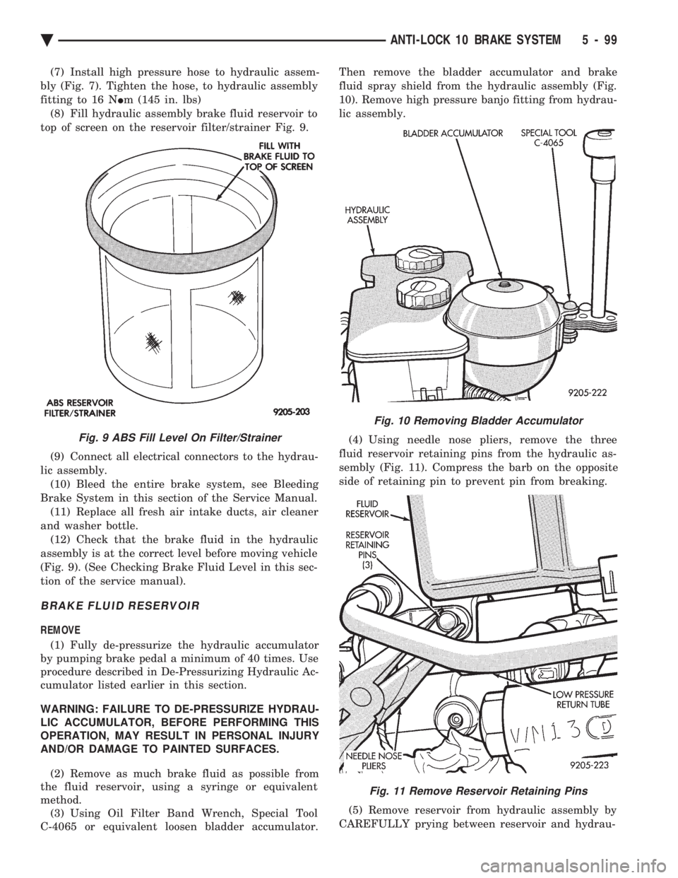
(8) Fill hydraulic assembly brake fluid reservoir to
top of screen on the reservoir filter/strainer Fig. 9.
(9) Connect all electrical connectors to the hydrau-
lic assembly. (10) Bleed the entire brake system, see Bleeding
Brake System in this section of the Service Manual. (11) Replace all fresh air intake ducts, air cleaner
and washer bottle. (12) Check that the brake fluid in the hydraulic
assembly is at the correct level before moving vehicle
(Fig. 9). (See Checking Brake Fluid Level in this sec-
tion of the service manual).
BRAKE FLUID RESERVOIR
REMOVE
(1) Fully de-pressurize the hydraulic accumulator
by pumping brake pedal a minimum of 40 times. Use
procedure described in De-Pressurizing Hydraulic Ac-
cumulator listed earlier in this section.
WARNING: FAILURE TO DE-PRESSURIZE HYDRAU-
LIC ACCUMULATOR, BEFORE PERFORMING THIS
OPERATION, MAY RESULT IN PERSONAL INJURY
AND/OR DAMAGE TO PAINTED SURFACES.
(2) Remove as much brake fluid as possible from
the fluid reservoir, using a syringe or equivalent
method. (3) Using Oil Filter Band Wrench, Special Tool
C-4065 or equivalent loosen bladder accumulator. Then remove the bladder accumulator and brake
fluid spray shield from the hydraulic assembly (Fig.
10). Remove high pressure banjo fitting from hydrau-
lic assembly.
(4) Using needle nose pliers, remove the three
fluid reservoir retaining pins from the hydraulic as-
sembly (Fig. 11). Compress the barb on the opposite
side of retaining pin to prevent pin from breaking.
(5) Remove reservoir from hydraulic assembly by
CAREFULLY prying between reservoir and hydrau-
Fig. 9 ABS Fill Level On Filter/Strainer
Fig. 10 Removing Bladder Accumulator
Fig. 11 Remove Reservoir Retaining Pins
Ä ANTI-LOCK 10 BRAKE SYSTEM 5 - 99