oil dipstick CHEVROLET PLYMOUTH ACCLAIM 1993 Service Manual
[x] Cancel search | Manufacturer: CHEVROLET, Model Year: 1993, Model line: PLYMOUTH ACCLAIM, Model: CHEVROLET PLYMOUTH ACCLAIM 1993Pages: 2438, PDF Size: 74.98 MB
Page 45 of 2438
² SG service engine oil is a high quality crankcase
lubricant designed for use in all naturally aspirated
engines. If SG service engine oil is used in turbo-
charged engine, change engine oil at every 4 800
km (3,000 miles) or three months.
² SG/CD service engine oil is a high quality crank-
case lubricant designed for use in most naturally as-
pirated and turbocharged gasoline or diesel engines.
FLEXIBLE FUEL VEHICLES
Vehicles operated using Flexible Fuel (M85) re-
quire engine oil that meet or exceed Chrysler Stan-
dard MS-9214. Mopar Flexible Fuel engine oil or
equivalent should be used when adding or changing
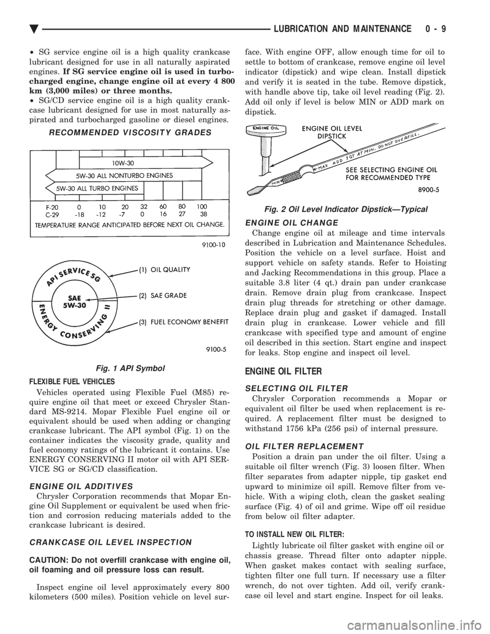
crankcase lubricant. The API symbol (Fig. 1) on the
container indicates the viscosity grade, quality and
fuel economy ratings of the lubricant it contains. Use
ENERGY CONSERVING II motor oil with API SER-
VICE SG or SG/CD classification.
ENGINE OIL ADDITIVES
Chrysler Corporation recommends that Mopar En-
gine Oil Supplement or equivalent be used when fric-
tion and corrosion reducing materials added to the
crankcase lubricant is desired.
CRANKCASE OIL LEVEL INSPECTION
CAUTION: Do not overfill crankcase with engine oil,
oil foaming and oil pressure loss can result.
Inspect engine oil level approximately every 800
kilometers (500 miles). Position vehicle on level sur- face. With engine OFF, allow enough time for oil to
settle to bottom of crankcase, remove engine oil level
indicator (dipstick) and wipe clean. Install dipstick
and verify it is seated in the tube. Remove dipstick,
with handle above tip, take oil level reading (Fig. 2).
Add oil only if level is below MIN or ADD mark on
dipstick.
ENGINE OIL CHANGE
Change engine oil at mileage and time intervals
described in Lubrication and Maintenance Schedules.
Position the vehicle on a level surface. Hoist and
support vehicle on safety stands. Refer to Hoisting
and Jacking Recommendations in this group. Place a
suitable 3.8 liter (4 qt.) drain pan under crankcase
drain. Remove drain plug from crankcase. Inspect
drain plug threads for stretching or other damage.
Replace drain plug and gasket if damaged. Install
drain plug in crankcase. Lower vehicle and fill
crankcase with specified type and amount of engine
oil described in this section. Start engine and inspect
for leaks. Stop engine and inspect oil level.
ENGINE OIL FILTER
SELECTING OIL FILTER
Chrysler Corporation recommends a Mopar or
equivalent oil filter be used when replacement is re-
quired. A replacement filter must be designed to
withstand 1756 kPa (256 psi) of internal pressure.
OIL FILTER REPLACEMENT
Position a drain pan under the oil filter. Using a
suitable oil filter wrench (Fig. 3) loosen filter. When
filter separates from adapter nipple, tip gasket end
upward to minimize oil spill. Remove filter from ve-
hicle. With a wiping cloth, clean the gasket sealing
surface (Fig. 4) of oil and grime. Wipe off oil residue
from below oil filter adapter.
TO INSTALL NEW OIL FILTER: Lightly lubricate oil filter gasket with engine oil or
chassis grease. Thread filter onto adapter nipple.
When gasket makes contact with sealing surface,
tighten filter one full turn. If necessary use a filter
wrench, do not over tighten. Add oil, verify crank-
case oil level and start engine. Inspect for oil leaks.
RECOMMENDED VISCOSITY GRADES
Fig. 1 API Symbol
Fig. 2 Oil Level Indicator DipstickÐTypical
Ä LUBRICATION AND MAINTENANCE 0 - 9
Page 52 of 2438
DRIVETRAIN INDEX
page page
Automatic Transaxle ...................... 16
Automatic Transaxle Floor Shift .............. 16
Clutch and Gearshift Linkage ............... 16
Drive Shaft Cv and Tripod Joint Boots ........ 17 Front Wheel Bearings
..................... 17
Manual Transaxle ........................ 16
Tires .................................. 17
CLUTCH AND GEARSHIFT LINKAGE
If the clutch or gearshift begins to operate with dif-
ficulty, squeak or grunt, the cables and linkage
should be lubricated before service replacement is
performed. For proper lubrication and service proce-
dures refer to Group 6, Clutch, or Group 21, Manual
Transaxle.
MANUAL TRANSAXLE
The manual transaxle should be inspected for oil
leaks and proper oil level when other under vehicle
service is performed. To inspect the transaxle oil
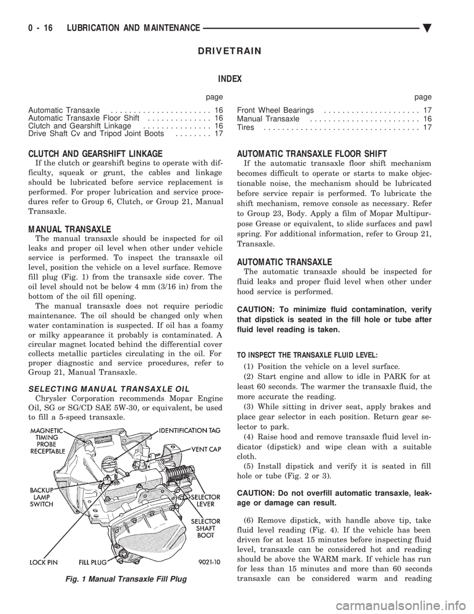
level, position the vehicle on a level surface. Remove
fill plug (Fig. 1) from the transaxle side cover. The
oil level should not be below 4 mm (3/16 in) from the
bottom of the oil fill opening. The manual transaxle does not require periodic
maintenance. The oil should be changed only when
water contamination is suspected. If oil has a foamy
or milky appearance it probably is contaminated. A
circular magnet located behind the differential cover
collects metallic particles circulating in the oil. For
proper diagnostic and service procedures, refer to
Group 21, Manual Transaxle.
SELECTING MANUAL TRANSAXLE OIL
Chrysler Corporation recommends Mopar Engine
Oil, SG or SG/CD SAE 5W-30, or equivalent, be used
to fill a 5-speed transaxle.
AUTOMATIC TRANSAXLE FLOOR SHIFT
If the automatic transaxle floor shift mechanism
becomes difficult to operate or starts to make objec-
tionable noise, the mechanism should be lubricated
before service repair is performed. To lubricate the
shift mechanism, remove console as necessary. Refer
to Group 23, Body. Apply a film of Mopar Multipur-
pose Grease or equivalent, to slide surfaces and pawl
spring. For additional information, refer to Group 21,
Transaxle.
AUTOMATIC TRANSAXLE
The automatic transaxle should be inspected for
fluid leaks and proper fluid level when other under
hood service is performed.
CAUTION: To minimize fluid contamination, verify
that dipstick is seated in the fill hole or tube after
fluid level reading is taken.
TO INSPECT THE TRANSAXLE FLUID LEVEL: (1) Position the vehicle on a level surface.
(2) Start engine and allow to idle in PARK for at
least 60 seconds. The warmer the transaxle fluid, the
more accurate the reading. (3) While sitting in driver seat, apply brakes and
place gear selector in each position. Return gear se-
lector to park. (4) Raise hood and remove transaxle fluid level in-
dicator (dipstick) and wipe clean with a suitable
cloth. (5) Install dipstick and verify it is seated in fill
hole or tube (Fig. 2 or 3).
CAUTION: Do not overfill automatic transaxle, leak-
age or damage can result.
(6) Remove dipstick, with handle above tip, take
fluid level reading (Fig. 4). If the vehicle has been
driven for at least 15 minutes before inspecting fluid
level, transaxle can be considered hot and reading
should be above the WARM mark. If vehicle has run
for less than 15 minutes and more than 60 seconds
transaxle can be considered warm and reading
Fig. 1 Manual Transaxle Fill Plug
0 - 16 LUBRICATION AND MAINTENANCE Ä
Page 53 of 2438
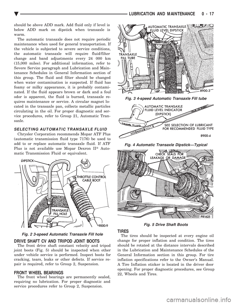
should be above ADD mark. Add fluid only if level is
below ADD mark on dipstick when transaxle is
warm.The automatic transaxle does not require periodic
maintenance when used for general transportation. If
the vehicle is subjected to severe service conditions,
the automatic transaxle will require fluid/filter
change and band adjustments every 24 000 km
(15,000 miles). For additional information, refer to
Severe Service paragraph and Lubrication and Main-
tenance Schedules in General Information section of
this group. The fluid and filter should be changed
when water contamination is suspected. If fluid has
foamy or milky appearance, it is probably contami-
nated. If the fluid appears brown or dark and a foul
odor is apparent, the fluid is burned, transaxle re-
quires maintenance or service. A circular magnet lo-
cated in the transaxle pan, collects metallic particles
circulating in the oil. For proper diagnostic and ser-
vice procedures, refer to Group 21, Automatic Tran-
saxle.
SELECTING AUTOMATIC TRANSAXLE FLUID
Chrysler Corporation recommends Mopar ATF Plus
(automatic transmission fluid type 7176) be used to
add to or replace automatic transaxle fluid. If ATF
Plus is not available use Mopar Dexron II tAuto-
matic Transmission Fluid or equivalent.
DRIVE SHAFT CV AND TRIPOD JOINT BOOTS
The front drive shaft constant velocity and tripod
joint boots (Fig. 5) should be inspected when other
under vehicle service is performed. Inspect boots for
cracking, tears, leaks or other defects. If service re-
pair is required, refer to Group 2, Suspension.
FRONT WHEEL BEARINGS
The front wheel bearings are permanently sealed,
requiring no lubrication. For proper diagnostic and
service procedures refer to Group 2, Suspension.
TIRES
The tires should be inspected at every engine oil
change for proper inflation and condition. The tires
should be rotated at the distance intervals described
in the Lubrication and Maintenance Schedules of the
General Information section in this group. For tire
inflation specifications refer to the Owner's Manual.
A Tire Inflation sticker is located in the driver door
opening. For proper diagnostic procedures, see Group
22, Wheels and Tires.Fig. 2 3-speed Automatic Transaxle Fill hole
Fig. 3 4-speed Automatic Transaxle Fill tube
Fig. 4 Automatic Transaxle DipstickÐTypical
Fig. 5 Drive Shaft Boots
Ä LUBRICATION AND MAINTENANCE 0 - 17
Page 56 of 2438
The power steering pump drive belt should be in-
spected at the time and distance interval described in
the Lubrication and Maintenance Schedules. Refer to
the General Information section of this group.
POWER STEERING FLUID INSPECTION
WARNING: ENGINE MUST NOT BE RUNNING WHEN
INSPECTING POWER STEERING FLUID LEVEL,
PERSONAL INJURY CAN RESULT.
CAUTION: Do not over fill power steering reservoir
when adding fluid, seal damage and leakage can re-
sult.
TO INSPECT FLUID LEVEL:
(1) Position vehicle on a level surface with engine
at normal running temperature. (2) Turn OFF engine and remove ignition key.
(3) Using a wiping cloth, clean oil and dirt residue
from around power steering reservoir cap. (4) Remove reservoir cap or dipstick and wipe off
fluid. (5) Install cap or dipstick.
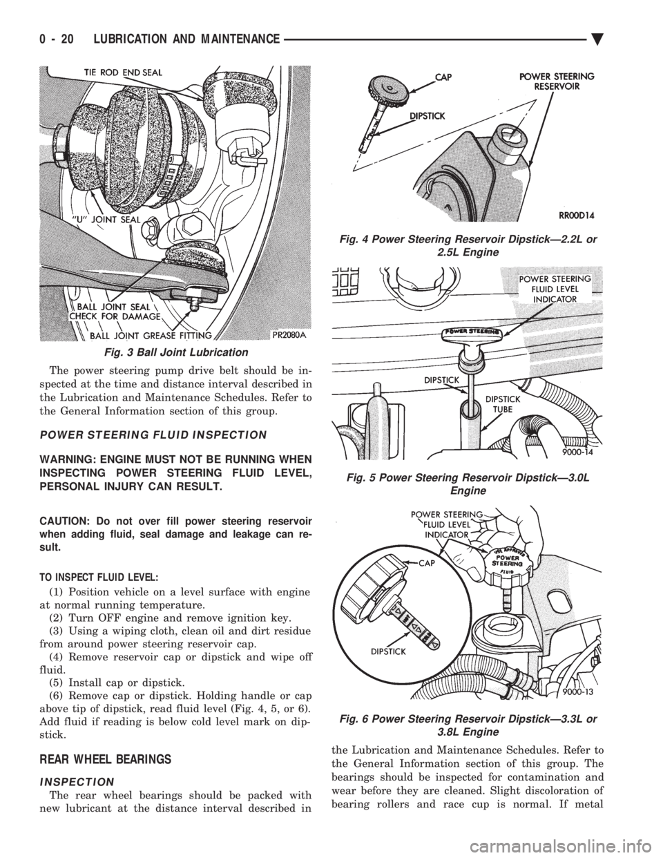
(6) Remove cap or dipstick. Holding handle or cap
above tip of dipstick, read fluid level (Fig. 4, 5, or 6).
Add fluid if reading is below cold level mark on dip-
stick.
REAR WHEEL BEARINGS
INSPECTION
The rear wheel bearings should be packed with
new lubricant at the distance interval described in the Lubrication and Maintenance Schedules. Refer to
the General Information section of this group. The
bearings should be inspected for contamination and
wear before they are cleaned. Slight discoloration of
bearing rollers and race cup is normal. If metal
Fig. 3 Ball Joint Lubrication
Fig. 4 Power Steering Reservoir DipstickÐ2.2L or 2.5L Engine
Fig. 5 Power Steering Reservoir DipstickÐ3.0L Engine
Fig. 6 Power Steering Reservoir DipstickÐ3.3L or3.8L Engine
0 - 20 LUBRICATION AND MAINTENANCE Ä
Page 424 of 2438
VISUAL MESSAGES
Following are the visual messages and the condi-
tions under which, the messages will be given:
² Keys in ignition
² Exterior lamps on
These messages will appear if the conditions are
present and the driver's door is open while the igni-
tion switch is in the OFF, LOCK, or ACC positions.
A tone will sound until the condition is corrected or
the door is closed.
² Passenger door ajar
² Driver door ajar
² Trunk ajar
² Park brake engaged
² Right rear door ajar
² Left rear door ajar
These messages will appear if a condition is de-
tected after the vehicle is in motion. When the con-
dition is corrected, a short tone will sound to
acknowledge the action. LOW OIL PRESSURE
If this message is displayed while the vehicle is at
cruising speeds, immediate attention is required. If
this message appears at idle speed, increase the idle
speed and the message should go off. If the message
remains on, immediate attention is required. ENGINE TEMP CRITICAL
This message appears when a sensor has determined
that the engine coolant is overheating. If this message
comes on and stays on, immediate action is required.
COOLANT LEVEL LOW
LOW FUEL LEVEL
LOW BRAKE FLUID
WASHER FLUID LOW
These messages will appear if a continuous warn-
ing condition is detected while the engine is running.
Inspection is required. To clear this message from
the display, after the condition is corrected, the igni-
tion switch must be turned OFF. CHECK TRANS
This message will appear if a continuous warning
condition is detected while the engine is running. Im-
mediate attention is recommended. To clear this mes-
sage from the display, after the condition has been
corrected, the ignition switch must be turned OFF. VOLTAGE IMPROPER
This message will appear if a continuous warning
condition is detected. Immediate attention is re-
quired. To clear this message from the display, after
the condition has been corrected, the ignition switch
must be turned OFF. TURN SIGNAL ON
This message will appear if the turn signal is left
on while vehicle speed is over 15 mph and the vehi-
cle has traveled over one-half mile. FASTEN SEAT BELTS An intermittent chime tone will sound for several
seconds if the seat belt is not fastened. CHK ENGINE OIL LEVEL
If this message is delivered, a check of the engine
oil dipstick is suggested. To clear this message, after
the condition is corrected, the ignition switch must
be turned OFF. HEADLAMP OUT
BRAKE LAMP OUT
TAIL LAMP OUT
These conditions are monitored only when the lamps
are on. The message will remain, even after the lamp is
replaced, until the lamp is turned on and operates.
SERVICE REMINDER
The maintenance reminder statement is programmed
to provide general information only. Refer to Group 0,
Lubrication & Maintenance for specific vehicle require-
ments.
The service reminder message is displayed at 7,500
miles or 12 months intervals, which ever comes first. MONITORED SYSTEMS OK
If there is no warning condition to report, the mes-
sage Monitored Systems OK is displayed (Fig. 2).
AUTOMATIC CALIBRATION SET PROCEDURE
The engine compartment node will continuously
and automatically recalibrate the compass under nor-
mal driving conditions. As long as the vehicle is
turning, the engine compartment node will record
new compass data. This new data will be used to
recalibrate the compass at a rate of at least once per
full (360 degree) turn of the vehicle. Automatic cali-
bration does not require operator interface.
MANUAL CALIBRATION SET PROCEDURE
Manual compass calibration has been replaced by
automatic calibration set procedure. The manual cal-
ibration set procedure is available, but no longer
serves any useful purpose.
EVIC SELF CHECK DIAGNOSTICS
Ignition switch ON, the EVIC not displaying any
message, may imply a system failure and not an
EVIC failure. Turn the ignition OFF, close all vehi-
cle doors and wait at least 60 seconds before begin-
ning test. Turn ignition switch to the ON position.
Pressing the TEMP, FUEL and INFO buttons at the
same time shall provide the visual message MOD-
ULE SELF CHECK for two seconds. Following at
two second interval there will be messages:
² E2-0 SELF CHECK
² E3-0 SELF CHECK
² END OF SELF CHECK
Showing the microcomputer is working properly.
When the self check mode and message shows:
² E2-1
² E3-2
This would show a fault exists in the EVIC's micro-
computer and the EVIC should be replaced (Fig. 3).
8C - 8 OVERHEAD CONSOLE Ä
Page 431 of 2438
VISUAL MESSAGES
Following are the visual messages and the condi-
tions under which, the messages will be given:
² Keys in ignition
² Exterior lamps on
These messages will appear if the conditions are
present and the driver's door is open while the igni-
tion switch is in the OFF, LOCK, or ACC positions.
A tone will sound until the condition is corrected or
the door is closed.
² Passenger door ajar
² Driver door ajar
² Trunk ajar
² Park brake engaged
² Right rear door ajar
² Left rear door ajar
These messages will appear if a condition is de-
tected after the vehicle is in motion. When the con-
dition is corrected, a short tone will sound to
acknowledge the action. LOW OIL PRESSURE
If this message is displayed while the vehicle is at
cruising speeds, immediate attention is required. If
this message appears at idle speed, increase the idle
speed and the message should go off. If the message
remains on, immediate attention is required. ENGINE TEMP CRITICAL
This message appears when a sensor has deter-
mined that the engine coolant is overheating. If this
message comes on and stays on, immediate action is
required. COOLANT LEVEL LOW
LOW FUEL LEVEL
LOW BRAKE FLUID WASHER FLUID LOW
These messages will appear if a continuous warn-
ing condition is detected while the engine is running.
Inspection is required. To clear this message from
the display, after the condition is corrected, the igni-
tion switch must be turned OFF. CHECK TRANS
This message will appear if a continuous warning
condition is detected while the engine is running. Im-
mediate attention is recommended. To clear this mes-
sage from the display, after the condition has been
corrected, the ignition switch must be turned OFF. VOLTAGE IMPROPER
This message will appear if a continuous warning
condition is detected. Immediate attention is re-
quired. To clear this message from the display, after
the condition has been corrected, the ignition switch
must be turned OFF. TURN SIGNAL ON
This message will appear if the turn signal is left
on while vehicle speed is over 15 mph and the vehi-
cle has traveled over one-half mile. FASTEN SEAT BELTS
An intermittent chime tone will sound for several
seconds if the seat belt is not fastened. CHK ENGINE OIL LEVEL
If this message is delivered, a check of the engine
oil dipstick is suggested. To clear this message, after
the condition is corrected, the ignition switch must
be turned OFF. HEADLAMP OUT
BRAKE LAMP OUT
TAIL LAMP OUT
These conditions are monitored only when the
lamps are on. The message will remain, even after
the lamp is replaced, until the lamp is turned on and
operates. SERVICE REMINDER
The maintenance reminder statement is pro-
grammed to provide general information only. Refer
to Group 0, Lubrication & Maintenance for specific
vehicle requirements. The service reminder message is displayed at 7,500
miles or 12 months intervals, which ever comes first. MONITORED SYSTEMS OK
If there is no warning condition to report, the mes-
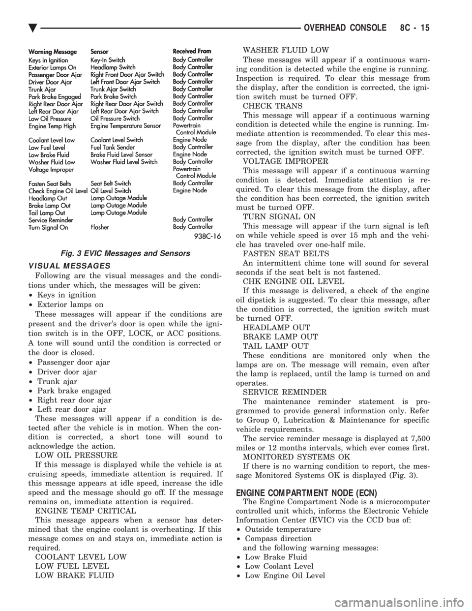
sage Monitored Systems OK is displayed (Fig. 3).
ENGINE COMPARTMENT NODE (ECN)
The Engine Compartment Node is a microcomputer
controlled unit which, informs the Electronic Vehicle
Information Center (EVIC) via the CCD bus of:
² Outside temperature
² Compass direction
and the following warning messages:
² Low Brake Fluid
² Low Coolant Level
² Low Engine Oil Level
Fig. 3 EVIC Messages and Sensors
Ä OVERHEAD CONSOLE 8C - 15
Page 1592 of 2438
valve spring retainer locks to become dislocated
when depressing the valve spring. Check and make
sure the locks are in their proper location. (3) Install valve cover as previously outlined in
this section.
VALVE SPRINGS AND VALVE STEM SEALS
REMOVAL
(1) Remove rocker arms as previously outlined in
this section. (2) Rotate crankshaft until piston is at TDC on
compression. (3) With air hose attached to adapter tool installed
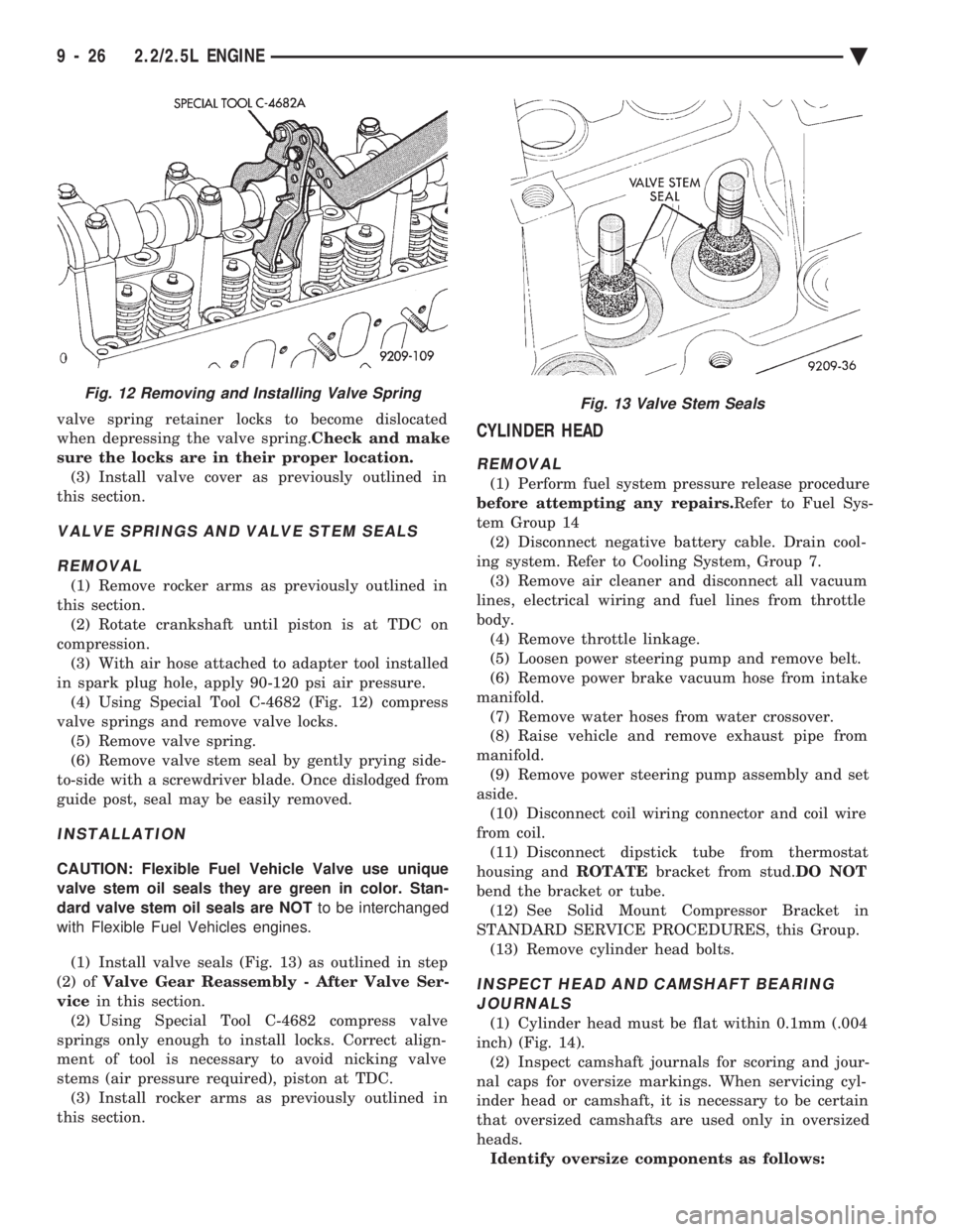
in spark plug hole, apply 90-120 psi air pressure. (4) Using Special Tool C-4682 (Fig. 12) compress
valve springs and remove valve locks. (5) Remove valve spring.
(6) Remove valve stem seal by gently prying side-
to-side with a screwdriver blade. Once dislodged from
guide post, seal may be easily removed.
INSTALLATION
CAUTION: Flexible Fuel Vehicle Valve use unique
valve stem oil seals they are green in color. Stan-
dard valve stem oil seals are NOT to be interchanged
with Flexible Fuel Vehicles engines.
(1) Install valve seals (Fig. 13) as outlined in step
(2) of Valve Gear Reassembly - After Valve Ser-
vice in this section.
(2) Using Special Tool C-4682 compress valve
springs only enough to install locks. Correct align-
ment of tool is necessary to avoid nicking valve
stems (air pressure required), piston at TDC. (3) Install rocker arms as previously outlined in
this section.
CYLINDER HEAD
REMOVAL
(1) Perform fuel system pressure release procedure
before attempting any repairs. Refer to Fuel Sys-
tem Group 14 (2) Disconnect negative battery cable. Drain cool-
ing system. Refer to Cooling System, Group 7. (3) Remove air cleaner and disconnect all vacuum
lines, electrical wiring and fuel lines from throttle
body. (4) Remove throttle linkage.
(5) Loosen power steering pump and remove belt.
(6) Remove power brake vacuum hose from intake
manifold. (7) Remove water hoses from water crossover.
(8) Raise vehicle and remove exhaust pipe from
manifold. (9) Remove power steering pump assembly and set
aside. (10) Disconnect coil wiring connector and coil wire
from coil. (11) Disconnect dipstick tube from thermostat
housing and ROTATEbracket from stud. DO NOT
bend the bracket or tube. (12) See Solid Mount Compressor Bracket in
STANDARD SERVICE PROCEDURES, this Group. (13) Remove cylinder head bolts.
INSPECT HEAD AND CAMSHAFT BEARINGJOURNALS
(1) Cylinder head must be flat within 0.1mm (.004
inch) (Fig. 14). (2) Inspect camshaft journals for scoring and jour-
nal caps for oversize markings. When servicing cyl-
inder head or camshaft, it is necessary to be certain
that oversized camshafts are used only in oversized
heads. Identify oversize components as follows:
Fig. 12 Removing and Installing Valve SpringFig. 13 Valve Stem Seals
9 - 26 2.2/2.5L ENGINE Ä
Page 1593 of 2438
Cylinder Head: Top of bearing caps painted green
and O/SJ stamped rearward of oil gallery plug on end
of head. Camshaft: Barrel of camshaft painted greenand
O/SJ stamped on end of shaft.
CLEANING
Remove all gasket material from cylinder head and
block. Be careful not gouge or scratch the aluminum
head sealing surface.
INSTALLATION
CAUTION: Head bolt diameter is 11mm. These bolts
are identified with 11 on the head of the bolt. 10mm
bolts will thread into the 11mm hole but will strip the
cylinder block bolt hole .
Since the Cylinder head bolts are torqued us-
ing a new procedure they should be examined
BEFORE reuse. If the threads are necked down
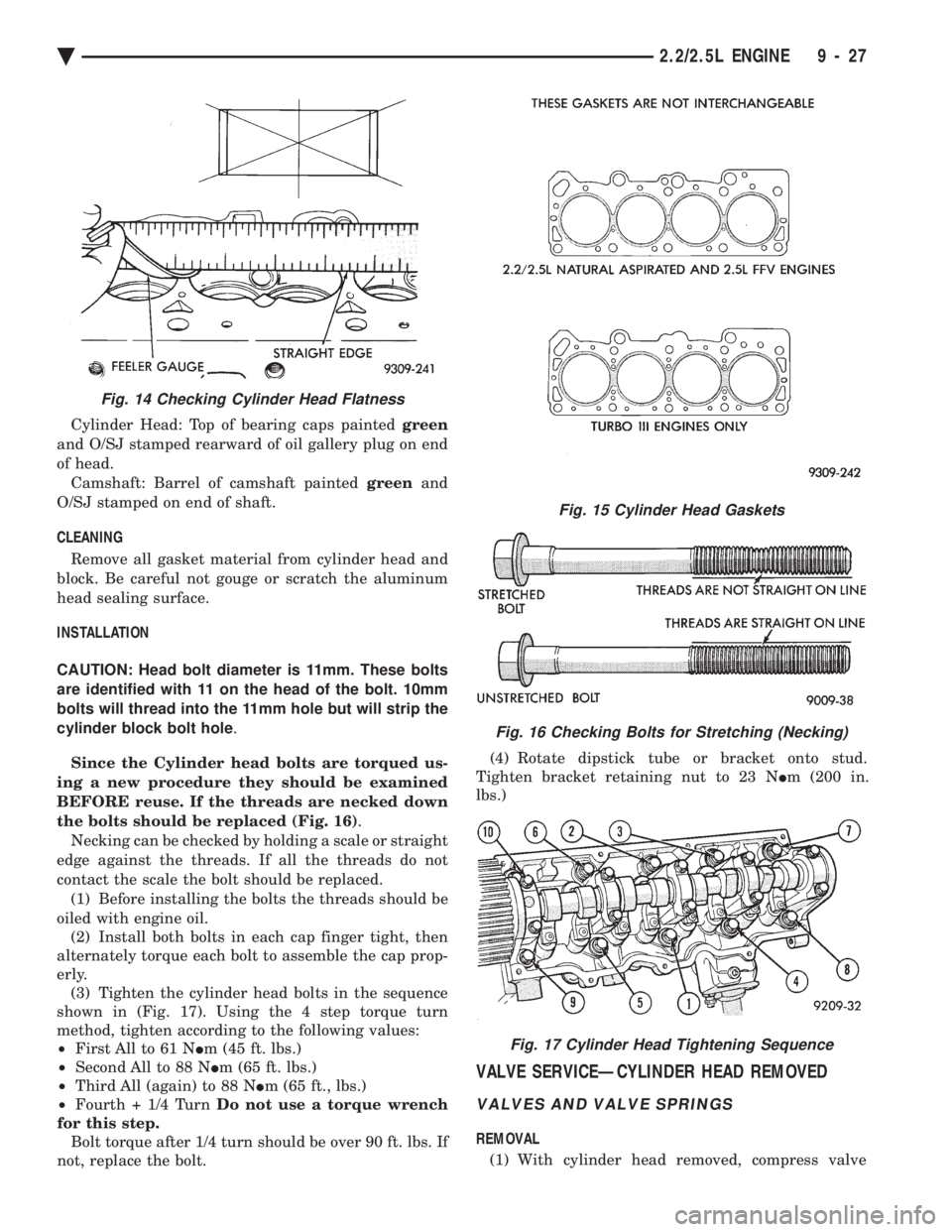
the bolts should be replaced (Fig. 16) .
Necking can be checked by holding a scale or straight
edge against the threads. If all the threads do not
contact the scale the bolt should be replaced. (1) Before installing the bolts the threads should be
oiled with engine oil. (2) Install both bolts in each cap finger tight, then
alternately torque each bolt to assemble the cap prop-
erly. (3) Tighten the cylinder head bolts in the sequence
shown in (Fig. 17). Using the 4 step torque turn
method, tighten according to the following values:
² First All to 61 N Im (45 ft. lbs.)
² Second All to 88 N Im (65 ft. lbs.)
² Third All (again) to 88 N Im (65 ft., lbs.)
² Fourth + 1/4 Turn Do not use a torque wrench
for this step. Bolt torque after 1/4 turn should be over 90 ft. lbs. If
not, replace the bolt. (4) Rotate dipstick tube or bracket onto stud.
Tighten bracket retaining nut to 23 N Im (200 in.
lbs.)
VALVE SERVICEÐCYLINDER HEAD REMOVED
VALVES AND VALVE SPRINGS
REMOVAL
(1) With cylinder head removed, compress valve
Fig. 15 Cylinder Head Gaskets
Fig. 16 Checking Bolts for Stretching (Necking)
Fig. 17 Cylinder Head Tightening Sequence
Fig. 14 Checking Cylinder Head Flatness
Ä 2.2/2.5L ENGINE 9 - 27
Page 1674 of 2438
(15) Install rocker arm covers tighten screws to 14
N Im (120 in. lbs.) and connector to ignition coils.
(16) Install Intake Manifold; Refer to Intake Mani-
fold Installation 3.3/3.8L Engine, Group 11 Exhaust
System and Intake Manifold.
HYDRAULIC TAPPETS
The valve train includes roller tappet assemblies,
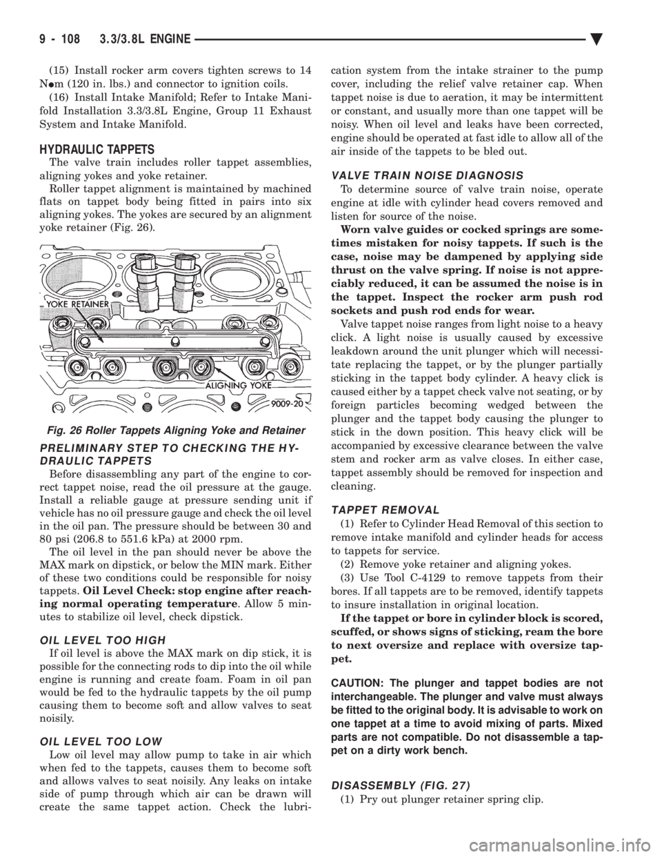
aligning yokes and yoke retainer. Roller tappet alignment is maintained by machined
flats on tappet body being fitted in pairs into six
aligning yokes. The yokes are secured by an alignment
yoke retainer (Fig. 26).
PRELIMINARY STEP TO CHECKING THE HY- DRAULIC TAPPETS
Before disassembling any part of the engine to cor-
rect tappet noise, read the oil pressure at the gauge.
Install a reliable gauge at pressure sending unit if
vehicle has no oil pressure gauge and check the oil level
in the oil pan. The pressure should be between 30 and
80 psi (206.8 to 551.6 kPa) at 2000 rpm. The oil level in the pan should never be above the
MAX mark on dipstick, or below the MIN mark. Either
of these two conditions could be responsible for noisy
tappets. Oil Level Check: stop engine after reach-
ing normal operating temperature . Allow 5 min-
utes to stabilize oil level, check dipstick.
OIL LEVEL TOO HIGH
If oil level is above the MAX mark on dip stick, it is
possible for the connecting rods to dip into the oil while
engine is running and create foam. Foam in oil pan
would be fed to the hydraulic tappets by the oil pump
causing them to become soft and allow valves to seat
noisily.
OIL LEVEL TOO LOW
Low oil level may allow pump to take in air which
when fed to the tappets, causes them to become soft
and allows valves to seat noisily. Any leaks on intake
side of pump through which air can be drawn will
create the same tappet action. Check the lubri- cation system from the intake strainer to the pump
cover, including the relief valve retainer cap. When
tappet noise is due to aeration, it may be intermittent
or constant, and usually more than one tappet will be
noisy. When oil level and leaks have been corrected,
engine should be operated at fast idle to allow all of the
air inside of the tappets to be bled out.
VALVE TRAIN NOISE DIAGNOSIS
To determine source of valve train noise, operate
engine at idle with cylinder head covers removed and
listen for source of the noise. Worn valve guides or cocked springs are some-
times mistaken for noisy tappets. If such is the
case, noise may be dampened by applying side
thrust on the valve spring. If noise is not appre-
ciably reduced, it can be assumed the noise is in
the tappet. Inspect the rocker arm push rod
sockets and push rod ends for wear. Valve tappet noise ranges from light noise to a heavy
click. A light noise is usually caused by excessive
leakdown around the unit plunger which will necessi-
tate replacing the tappet, or by the plunger partially
sticking in the tappet body cylinder. A heavy click is
caused either by a tappet check valve not seating, or by
foreign particles becoming wedged between the
plunger and the tappet body causing the plunger to
stick in the down position. This heavy click will be
accompanied by excessive clearance between the valve
stem and rocker arm as valve closes. In either case,
tappet assembly should be removed for inspection and
cleaning.
TAPPET REMOVAL
(1) Refer to Cylinder Head Removal of this section to
remove intake manifold and cylinder heads for access
to tappets for service. (2) Remove yoke retainer and aligning yokes.
(3) Use Tool C-4129 to remove tappets from their
bores. If all tappets are to be removed, identify tappets
to insure installation in original location. If the tappet or bore in cylinder block is scored,
scuffed, or shows signs of sticking, ream the bore
to next oversize and replace with oversize tap-
pet.
CAUTION: The plunger and tappet bodies are not
interchangeable. The plunger and valve must always
be fitted to the original body. It is advisable to work on
one tappet at a time to avoid mixing of parts. Mixed
parts are not compatible. Do not disassemble a tap-
pet on a dirty work bench.
DISASSEMBLY (FIG. 27)
(1) Pry out plunger retainer spring clip.
Fig. 26 Roller Tappets Aligning Yoke and Retainer
9 - 108 3.3/3.8L ENGINE Ä
Page 1688 of 2438
ENGINE LUBRICATION SYSTEM
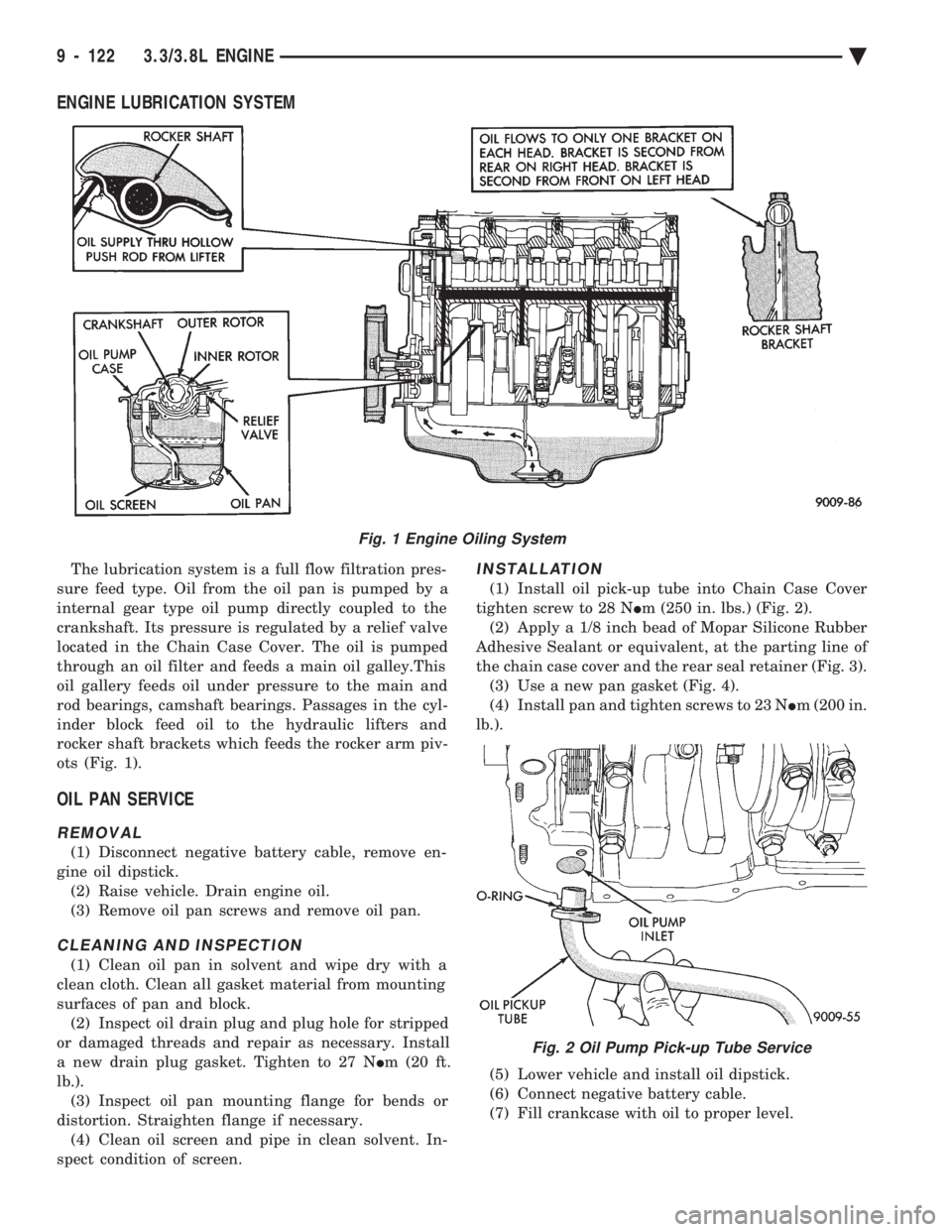
The lubrication system is a full flow filtration pres-
sure feed type. Oil from the oil pan is pumped by a
internal gear type oil pump directly coupled to the
crankshaft. Its pressure is regulated by a relief valve
located in the Chain Case Cover. The oil is pumped
through an oil filter and feeds a main oil galley.This
oil gallery feeds oil under pressure to the main and
rod bearings, camshaft bearings. Passages in the cyl-
inder block feed oil to the hydraulic lifters and
rocker shaft brackets which feeds the rocker arm piv-
ots (Fig. 1).
OIL PAN SERVICE
REMOVAL
(1) Disconnect negative battery cable, remove en-
gine oil dipstick. (2) Raise vehicle. Drain engine oil.
(3) Remove oil pan screws and remove oil pan.
CLEANING AND INSPECTION
(1) Clean oil pan in solvent and wipe dry with a
clean cloth. Clean all gasket material from mounting
surfaces of pan and block. (2) Inspect oil drain plug and plug hole for stripped
or damaged threads and repair as necessary. Install
a new drain plug gasket. Tighten to 27 N Im (20 ft.
lb.). (3) Inspect oil pan mounting flange for bends or
distortion. Straighten flange if necessary. (4) Clean oil screen and pipe in clean solvent. In-
spect condition of screen.
INSTALLATION
(1) Install oil pick-up tube into Chain Case Cover
tighten screw to 28 N Im (250 in. lbs.) (Fig. 2).
(2) Apply a 1/8 inch bead of Mopar Silicone Rubber
Adhesive Sealant or equivalent, at the parting line of
the chain case cover and the rear seal retainer (Fig. 3). (3) Use a new pan gasket (Fig. 4).
(4) Install pan and tighten screws to 23 N Im (200 in.
lb.).
(5) Lower vehicle and install oil dipstick.
(6) Connect negative battery cable.
(7) Fill crankcase with oil to proper level.
Fig. 1 Engine Oiling System
Fig. 2 Oil Pump Pick-up Tube Service
9 - 122 3.3/3.8L ENGINE Ä