trunk release CHEVROLET PLYMOUTH ACCLAIM 1993 Service Manual
[x] Cancel search | Manufacturer: CHEVROLET, Model Year: 1993, Model line: PLYMOUTH ACCLAIM, Model: CHEVROLET PLYMOUTH ACCLAIM 1993Pages: 2438, PDF Size: 74.98 MB
Page 132 of 2438
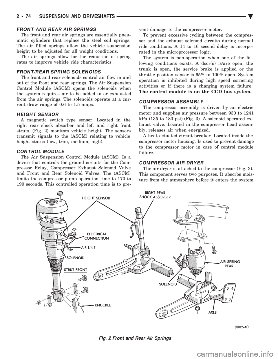
FRONT AND REAR AIR SPRINGS
The front and rear air springs are essentially pneu-
matic cylinders that replace the steel coil springs.
The air filled springs allow the vehicle suspension
height to be adjusted for all weight conditions. The air springs allow for the reduction of spring
rates to improve vehicle ride characteristics.
FRONT/REAR SPRING SOLENOIDS
The front and rear solenoids control air flow in and
out of the front and rear springs. The Air Suspension
Control Module (ASCM) opens the solenoids when
the system requires air to be added to or exhausted
from the air springs. The solenoids operate at a cur-
rent draw range of 0.6 to 1.5 amps.
HEIGHT SENSOR
A magnetic switch type sensor. Located in the
right rear shock absorber and left and right front
struts, (Fig. 2) monitors vehicle height. The sensors
transmit signals to the (ASCM) relating to vehicle
height status (low, trim, medium, high).
CONTROL MODULE
The Air Suspension Control Module (ASCM). Is a
device that controls the ground circuits for the Com-
pressor Relay, Compressor Exhaust Solenoid Valve
and Front and Rear Solenoid Valves. The (ASCM)
limits the compressor pump operation time to 170 to
190 seconds. This controlled operation time is to pre- vent damage to the compressor motor.
To prevent excessive cycling between the compres-
sor and the exhaust solenoid circuits during normal
ride conditions. A 14 to 16 second delay is incorpo-
rated in the microprocessor logic. The system is non-operation when one of the fol-
lowing conditions exists. A door(s) is/are open, the
trunk is open, the service brake is applied or the
throttle position sensor is 65% to 100% open. System
operation is inhibited during high speed cornering
activities or if there is a charging system failure.
The control module is on the CCD bus system.
COMPRESSOR ASSEMBLY
The compressor assembly is driven by an electric
motor and supplies air pressure between 930 to 1241
kPa (135 to 180 psi) (Fig. 3). A solenoid operated ex-
haust valve. Located in the compressor head assem-
bly, releases air when energized. A heat actuated circuit breaker. Located inside the
compressor motor housing. Is used to prevent damage
to the compressor motor in case of control module
failure.
COMPRESSOR AIR DRYER
The air dryer is attached to the compressor (Fig. 3).
This component serves two purposes. It absorbs mois-
ture from the atmosphere before it enters the system
Fig. 2 Front and Rear Air Springs
2 - 74 SUSPENSION AND DRIVESHAFTS Ä
Page 533 of 2438
(4) Remove panel top cover by pushing forward
and prying up, using a straight edge to assist in the
removal. (5) Disconnect bulkhead connector at brace under
instrument panel at left side. (6) Remove glovebox/ash receiver module and right
instrument panel silencer. (7) Remove center panel support brace and air bag
diagnostic module assembly. (8) Disconnect wiring to airbag module.
(9) Remove upper and lower cluster bezels.
(10) Remove steering column cover.
(11) Remove steering column mounting nuts and
lower steering column. (12) Unhook shift indicator cable eyelet from steer-
ing column actuator. (13) Unlatch lock tab in shift indicator column in-
sert and squeeze legs together to remove from steer-
ing column. (14) Remove cluster assembly while guiding trans-
mission range indicator guide tube through access
hole in the base panel. (15) Remove instrument panel steering column
opening support/hood release handle assembly. (16) Remove two steering column upper studs and
loosen side cowl tie-down bolts. (17) Remove steering column tilt lever.
(18) Remove upper and lower lock housing shroud.
(19) Remove lower fixed shroud.
(20) Remove upper fixed shroud (snaps in place).
(21) Disconnect airbag pigtail, ignition switch and
halo light/key buzzer switch wiring. (22) Disconnect Multi-function switch by loosening
connector jack screw and pulling connector from
switch. (23) Disconnect airbag pigtail from wiring trough
housing by pulling two push fasteners. (24) Remove wiring trough from steering column.
(25) Remove defroster ducts.
(26) Remove five screws along fence line and roll
panel down, attach a hook to hold in position. (27) Open hood and remove plenum grill.
(28) Disconnect washer bottle, resistor block and
under hood lamp wiring. Washer bottle must be re-
moved to gain access. (29) Remove grommet and pull plenum wiring into
vehicle through plenum panel. (30) Disconnect right demister hose from instru-
ment panel. (31) Disconnect antenna cable.
(32) Disconnect right and left 25 way body wiring
connectors. (33) Disconnect A/C heater control cables, wiring
connectors and vacuum harness. (34) Remove right side panel ground wire.
(35) Disconnect body controller wiring.
(36) Remove instrument panel assembly from vehi-
cle. (37) For installation reverse above procedures.
INTERIOR LAMP REPLACEMENT
The reading, overhead console and door lamps op-
erate when the doors are open or headlamp switch is
placed in courtesy position. Front overhead lamps re-
fer to Group 8C, Overhead Console.
TRUNK LAMP
The lamp has easily accessible without removing
components.
DOOR LAMP
Pry along the forward edge of the lens and pivot
lens out of the door trim panel. Remove lamp. To re-
move lamp housing, remove door trim panel. Refer to
Group 23, Body. Disconnect all wiring. Remove
screws, if so equipped securing lamp housing to trim
panel, and replace housing.
CÐPILLAR READING/COURTESY LAMP
Pry along the rearward edge of the lamp and pivot
lamp out from quarter trim panel. Disconnect wiring
and remove lamp cover. Replace lamp. The lamp operates when the doors are open or the
headlamp switch is turned to the courtesy mode. The
lamp will function as a reading lamp when the doors
are closed and the button switch on the lamp is de-
pressed.
ROOF RAIL READING
Pry along the bottom edge of the lens and pivot
lens out. Replace lamp. To remove the lamp, remove
the screw which retains the coat hook. Remove the
garnish molding. Disconnect the wiring harness. Re-
move the two clips which retain the lamp to the
molding. Replace lamp. The lamp operates like the
C-pillar reading/courtesy lamp.
Ä INSTRUMENT PANEL AND GAUGES 8E - 41
Page 549 of 2438
(11) Remove two screws from fuse block and lower
fuse block. (12) Remove three screws from hood release and
lower hood release handle. (13) Remove flasher relay from bracket on center
distribution duct. (14) Remove screw from ATC sensor motor assem-
bly and unhook from bracket if equipped. (15) Remove the radio ground screw above flasher
relay mount. (16) Remove center distribution duct screw from
left instrument panel lower brace, then remove four
screws to remove left lower brace.
(17) Remove five nuts on steering column and drop
column, then remove two upper column attaching studs.
(18) Remove two screws and pull out compact disc
player or cubby box, disconnect Co-Axial cable from
compact disc player. (19) Remove Electronic Vehicle Information Center
(E.V.I.C.) or Traveler from vehicle. (20) Remove radio.
(21) Remove A.T.C., A/C or heater controls. (22) Squeeze latches on side of Rear Window defog-
ger switch and remove. (23) Snap off cluster lower trim bezel, switch pod
vent grille, speaker grilles and defroster grilles. (24) Remove switch pod assembly.
(25) Remove cluster assembly.
(26) Remove dash speakers.
(27) Snap out bezel with or without message center
and disconnect wiring. (28) Open glovebox door, squeeze sides and roll
glovebox completely open. Remove glovebox light
switch, and disconnect wires. (29) Loosen right cowl side pivot bolt through
glovebox opening then close glovebox. (30) Loosen left cowl side pivot.
(31) Remove four screw attachments at top of in-
strument panel and roll panel out. (32) Pull wiring, antenna cable, A/C cable and vac-
uum lines out of instrument panel. Disconnect demis-
ter hose and remove instrument panel with ducts
attached. (33) Transfer ducts and brackets onto new panel.
(34) For instrument panel roll up, reverse
above procedures.
INTERIOR LAMP REMOVAL
The Dome, Floor Console and Door Lamps operate
when the doors are open or headlamp switch is
placed in courtesy position.
DOME LAMP
(1) Pry either the forward or rearward edge of the
dome lamp to free it from retaining bracket. (2) Pry either the forward or rearward edge of the
lens away from the bezel and replace lamp. (3) For installation reverse above procedures.
FRONT HEADER READING LAMP
Pull lamp from headliner. Disconnect wiring and
replace lamp.
FLOOR CONSOLE LAMP
Pry along top edge of lamp and pivot lamp out of
floor console, the lens does not remove. Remove lamp
and twist out lamp socket. Replace lamp.
DOOR LAMPS
Pry along bottom edge of lamp and pivot lamp out
of door trim panel, the lens does not remove. Remove
lamp and twist out lamp socket. Replace lamp.
DOOR REFLECTORS
Pry reflector away from the door trim panel, and
replace.
TRUNK LAMP
Remove lens by prying lens out of trunk trim panel
and replace bulb.
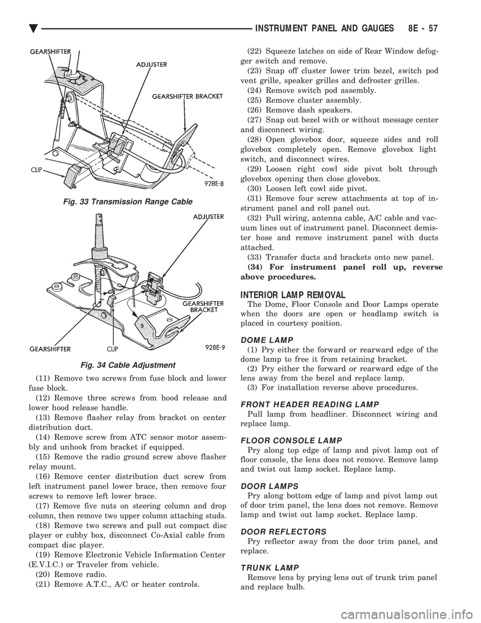
Fig. 33 Transmission Range Cable
Fig. 34 Cable Adjustment
Ä INSTRUMENT PANEL AND GAUGES 8E - 57
Page 658 of 2438
EXTERIOR LAMPSÐAJ BODY INDEX
page page
Back-Up Lamp .......................... 17
Back-Up Lamp Bulb ...................... 17
Center High Mounted Stop Lamp (CHMSL) Bulb . 18
Center High-Mounted Stop Lamp Assembly (CHMSL) ............................. 18
Cornering Lamp or Bulb ................... 16
Front Side Marker Lamp ................... 16
Front Side Marker Lamp Bulb ............... 16
Headlamp Module and Bulb ................ 16 Headlamps
............................. 16
License Plate Lamp or Bulb ................ 17
Park and Turn Signal Lamp or Bulb .......... 16
Rear Side Marker Lamp ................... 17
Rear Side Marker Lamp Bulb ............... 17
Tail, Stop, Turn Signal Bulb or Lamp ......... 17
Trunk Lid Tail Lamp ...................... 17
Trunk Lid Tail Lamp Bulb .................. 17
HEADLAMPS
HEADLAMP MODULE AND BULB
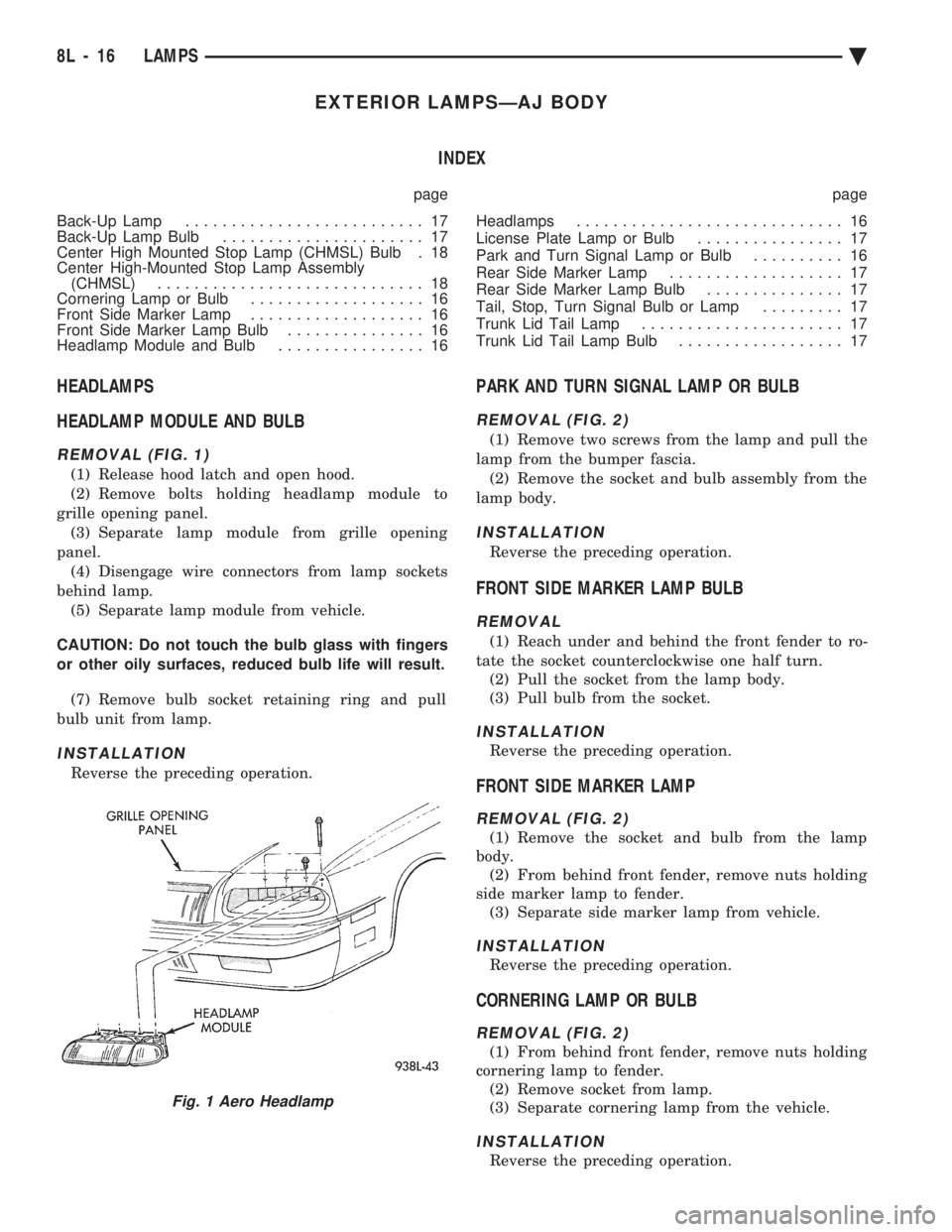
REMOVAL (FIG. 1)
(1) Release hood latch and open hood.
(2) Remove bolts holding headlamp module to
grille opening panel. (3) Separate lamp module from grille opening
panel. (4) Disengage wire connectors from lamp sockets
behind lamp. (5) Separate lamp module from vehicle.
CAUTION: Do not touch the bulb glass with fingers
or other oily surfaces, reduced bulb life will result. (7) Remove bulb socket retaining ring and pull
bulb unit from lamp.
INSTALLATION
Reverse the preceding operation.
PARK AND TURN SIGNAL LAMP OR BULB
REMOVAL (FIG. 2)
(1) Remove two screws from the lamp and pull the
lamp from the bumper fascia. (2) Remove the socket and bulb assembly from the
lamp body.
INSTALLATION
Reverse the preceding operation.
FRONT SIDE MARKER LAMP BULB
REMOVAL
(1) Reach under and behind the front fender to ro-
tate the socket counterclockwise one half turn. (2) Pull the socket from the lamp body.
(3) Pull bulb from the socket.
INSTALLATION
Reverse the preceding operation.
FRONT SIDE MARKER LAMP
REMOVAL (FIG. 2)
(1) Remove the socket and bulb from the lamp
body. (2) From behind front fender, remove nuts holding
side marker lamp to fender. (3) Separate side marker lamp from vehicle.
INSTALLATION
Reverse the preceding operation.
CORNERING LAMP OR BULB
REMOVAL (FIG. 2)
(1) From behind front fender, remove nuts holding
cornering lamp to fender. (2) Remove socket from lamp.
(3) Separate cornering lamp from the vehicle.
INSTALLATION
Reverse the preceding operation.
Fig. 1 Aero Headlamp
8L - 16 LAMPS Ä
Page 699 of 2438
to the deck lid open position. If the pull down limit
switch is depressed at this time, the motor should
stop.(c) If these results are not obtained, replace the
pull down motor assembly.
REMOTE KEYLESS ENTRY
OPERATION
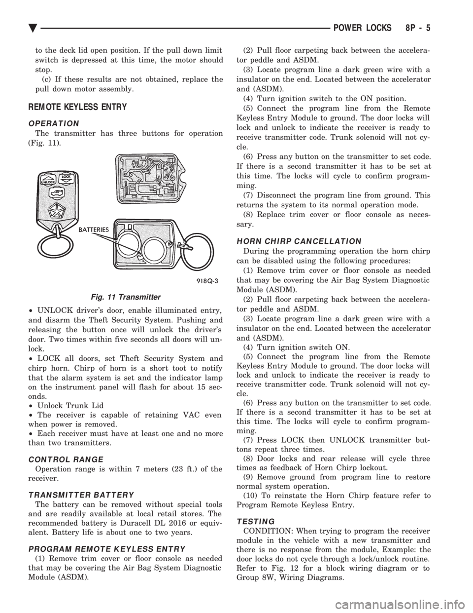
The transmitter has three buttons for operation
(Fig. 11).
² UNLOCK driver's door, enable illuminated entry,
and disarm the Theft Security System. Pushing and
releasing the button once will unlock the driver's
door. Two times within five seconds all doors will un-
lock.
² LOCK all doors, set Theft Security System and
chirp horn. Chirp of horn is a short toot to notify
that the alarm system is set and the indicator lamp
on the instrument panel will flash for about 15 sec-
onds.
² Unlock Trunk Lid
² The receiver is capable of retaining VAC even
when power is removed.
² Each receiver must have at least one and no more
than two transmitters.
CONTROL RANGE
Operation range is within 7 meters (23 ft.) of the
receiver.
TRANSMITTER BATTERY
The battery can be removed without special tools
and are readily available at local retail stores. The
recommended battery is Duracell DL 2016 or equiv-
alent. Battery life is about one to two years.
PROGRAM REMOTE KEYLESS ENTRY
(1) Remove trim cover or floor console as needed
that may be covering the Air Bag System Diagnostic
Module (ASDM). (2) Pull floor carpeting back between the accelera-
tor peddle and ASDM. (3) Locate program line a dark green wire with a
insulator on the end. Located between the accelerator
and (ASDM). (4) Turn ignition switch to the ON position.
(5) Connect the program line from the Remote
Keyless Entry Module to ground. The door locks will
lock and unlock to indicate the receiver is ready to
receive transmitter code. Trunk solenoid will not cy-
cle. (6) Press any button on the transmitter to set code.
If there is a second transmitter it has to be set at
this time. The locks will cycle to confirm program-
ming. (7) Disconnect the program line from ground. This
returns the system to its normal operation mode. (8) Replace trim cover or floor console as neces-
sary.
HORN CHIRP CANCELLATION
During the programming operation the horn chirp
can be disabled using the following procedures: (1) Remove trim cover or floor console as needed
that may be covering the Air Bag System Diagnostic
Module (ASDM). (2) Pull floor carpeting back between the accelera-
tor peddle and ASDM. (3) Locate program line a dark green wire with a
insulator on the end. Located between the accelerator
and (ASDM). (4) Turn ignition switch ON.
(5) Connect the program line from the Remote
Keyless Entry Module to ground. The door locks will
lock and unlock to indicate the receiver is ready to
receive transmitter code. Trunk solenoid will not cy-
cle. (6) Press any button on the transmitter to set code.
If there is a second transmitter it has to be set at
this time. The locks will cycle to confirm program-
ming. (7) Press LOCK then UNLOCK transmitter but-
tons repeat three times. (8) Door locks and rear release will cycle three
times as feedback of Horn Chirp lockout. (9) Remove ground from program line to restore
normal system operation. (10) To reinstate the Horn Chirp feature refer to
Program Remote Keyless Entry.
TESTING
CONDITION: When trying to program the receiver
module in the vehicle with a new transmitter and
there is no response from the module, Example: the
door locks do not cycle through a lock/unlock routine.
Refer to Fig. 12 for a block wiring diagram or to
Group 8W, Wiring Diagrams.
Fig. 11 Transmitter
Ä POWER LOCKS 8P - 5
Page 1064 of 2438
Wiring Diagram
Name Sheet Number
Relay Bank ............................. .106
Blower Slide Control ...........................51
Bulkhead Disconnect (50 Way) ................181, 182
Bulkhead Disconnect (50-Way) (2.5L Engine) .......183, 184
Bulkhead Disconnect (50-Way) (3.0L Engine) .......185, 186
Bulkhead Disconnect (50-Way) (3.3L & 3.8L Engine) ......................... .187, 188
Camshaft Position Sensor .......................28
Crankshaft Position Sensor .......................28
Cellular Phone System ........................ .126
Antenna ............................... .126
Center Phone ............................ .126
External Speaker .......................... .126
Microphone ............................. .126
Transmitter/Receiver Unit .................... .126
Visor Phone ............................. .126
Charging System (2.5L Engine) ...................5,6
Battery ...................................5
Generator .................................6
Power Distribution Center .......................6
Charging System (3.0L Engine) ...................7,8
Battery ...................................7
Generator .................................8
Power Distribution Center .......................8
Charging System (3.3L & 3.8L Engine) .............9,10
Battery ...................................9
Generator ................................10
Power Distribution Center ......................10
Cigar Lighter .......................... .111, 112
Circuit Breakers Concealed Headlamps .......................2,68
Power Door Locks ........................2,139
Power Seats ............................2,149
Power Windows .........................3,158
Compressor Motor ........................ .40, 42
Concealed Headlamp Controls .....................68
Circuit Breaker .............................68
Headlamp Door Motor ........................68
Headlamp Door Relays ........................68
Headlamp Relay ............................68
Relay Bank ...............................68
Courtesy Lamp System .................87, 88, 89, 90
Left Front Door Courtesy Lamp ..................87
Left Front Door Jamb Switch ....................87
Left Illuminated Visor Vanity Mirror ................89
Left Illuminated Visor Vanity Mirror Switch ...........89
Left Lamp and Switch ........................89
Left Rear Door Courtesy Lamp ...................87
Left Rear Door Jamb Switch ....................87
Left Rear Quarter Reading Lamp ..................90
Right Front Door Courtesy Lamp .................88
Right Front Door Jamb Switch ...................88
Right Illuminated Visor Vanity Mirror ...............89
Right Illuminated Visor Vanity Mirror Switch ..........89
Right Lamp and Switch .......................89
Right Rear Door Courtesy Lamp ..................88
Right Rear Door Jamb Switch ...................88Wiring Diagram
Name Sheet Number
Right Rear Quarter Reading Lamp .................90
Trunk Lamp ...............................90
Data Link Connectors ..........14, 23, 100, 103, 106, 110,
130, 134, 136
Deck Lid Release and Deck Lid Pull-Down System . . . .159, 160
Deck Lid Pull-Down Unit ..................... .160
Deck Lid Release Solenoid .................159, 160
Deck Lid Release Solenoid/Pull-Down Key Cylinder Switch ............................... .160
Mercury Switch .......................... .159
Underhood Light .......................... .159
Dimmer Switch-Optical Horn ....................1,66
Distributor .............................. .17, 19
Door Ajar System w/Electronic Cluster ...............92
Left Front Door Ajar Switch .....................92
Left Rear Door Ajar Switch .....................92
Right Front Door Ajar Switch ....................92
Right Rear Door Ajar Switch ....................92
Door Ajar System w/Mechanical Cluster and Visual Mess Ctr ...............................93
Left Front Door Ajar Switch .....................93
Left Rear Door Ajar Switch .....................93
Right Front Door Ajar Switch ....................93
Right Rear Door Ajar Switch ....................93
Door Ajar System w/Mechanical Cluster w/o Visual Mess Ctr ...............................94
Left Front Door Ajar Switch .....................94
Left Rear Door Ajar Switch .....................94
Right Front Door Ajar Switch ....................94
Right Rear Door Ajar Switch ....................94
Door Electrical Ground Systems ...................165
Door Jamb Courtesy Lamp Switches ..............87, 88
Door Lock System ....................... .139, 140
Circuit Breaker ........................... .139
Connector and Door Lock Switch Function .......139, 140
Door Lock Relay .......................... .140
Door Unlock Relay ......................... .140
Left Front Door Lock Motor ................... .139
Left Front Door Lock Switch ...................139
Left Rear Door Lock Motor ................... .139
Relay Bank ............................. .139
Right Front Door Lock Motor ...................140
Right Front Door Lock Switch ..................140
Right Rear Door Lock Motor ...................140
Exhaust Gas Recirculation Solenoid ............14, 21, 26
Electronically Tuned Stereo Radio ..............119, 120
Left Door Speaker ......................... .120
Left Rear Speaker ......................... .120
Right Door Speaker ........................ .120
Right Rear Speaker ........................ .120
Electronically Tuned Stereo Radio with RS Amplifier ....................... .121, 122, 123
Left Door Speaker ......................... .123
Left Front Speaker ......................... .123
Left Rear Speaker ......................... .123
Right Door Speaker ........................ .123
Right Front Speaker ........................ .123
Right Rear Speaker ........................ .123
8W - 314 WIRING DIAGRAMS AC-AY BODY Ä
Page 2167 of 2438
AA-VEHICLE BODY COMPONENT SERVICE INDEX
page page
A-Pillar and Roof Rail Mouldings ............. 25
B-Pillar Trim Panel ....................... 25
Body Side Moulding and Applique ............ 24
Cowl Cover ............................. 13
Cowl Panel Trim and Scuff Plates ............ 25
Door Opening Weatherstrips ................ 24
Floor Carpet ............................ 30
Front Center Console ..................... 29
Front Door and Hinge ..................... 15
Front Door Belt Moulding and Weatherstrip ..... 17
Front Door Glass ........................ 17
Front Door Glass Channel and Run Weatherstrip . 18
Front Door Glass Run Lower Channel ......... 18
Front Door Latch ......................... 16
Front Door Side View Mirror ................ 17
Front Door Silencer and Water Shield ......... 15
Front Door Trim Panel .................... 14
Front Door Window Regulator/Manual ......... 18
Front Door Window Regulator/Power .......... 19
Front End Splash Shields .................. 13
Front Fender ............................ 14
Front Power Door Lock Actuator ............. 19
Front Seat Belts ......................... 27
Front Seats ............................. 28
Fuel Fill Door ........................... 36
Grille .................................. 11
Head Lining ............................. 30
Hood and Hinges ........................ 11
Hood Latch and Release Cable .............. 12
Outside Front Door Latch Release Handle ..... 16
Outside Rear Door Latch Release Handle ...... 21 Overhead Console
........................ 30
Quarter Extension Trim Panel ............... 27
Quarter Trim Panel ....................... 27
Rear Deck Filler Panel .................... 31
Rear Door and Hinge ..................... 20
Rear Door Belt Moulding and Weatherstrip ..... 22
Rear Door Glass ......................... 22
Rear Door Glass Run Weatherstrip ........... 22
Rear Door Glass Stationary Glass Module ..... 23
Rear Door Latch ......................... 21
Rear Door Silencer and Water Shield ......... 20
Rear Door Trim Panel ..................... 20
Rear Door Window Regulator/Manual ......... 23
Rear Door Window Regulator/Power .......... 23
Rear Power Door Lock Actuator ............. 22
Rear Seat Belts .......................... 28
Rear Seats ............................. 28
Rear Shelf Trim Panel ..................... 27
Rear Window Glass ...................... 32
Sun Roof Air Deflector .................... 31
Sun Roof Drain Tubes .................... 31
Sun Roof Weatherstrip .................... 31
Trunk Lid .............................. 33
Trunk Lid Hinge ......................... 34
Trunk Lid Latch .......................... 34
Trunk Lid Lock .......................... 34
Trunk Lid Luggage Rack ................... 35
Trunk Lid Torsion Bar ..................... 34
Trunk Lining ............................ 35
Trunk Opening Weatherstrip ................ 35
Vinyl Roof Bonnet ........................ 31
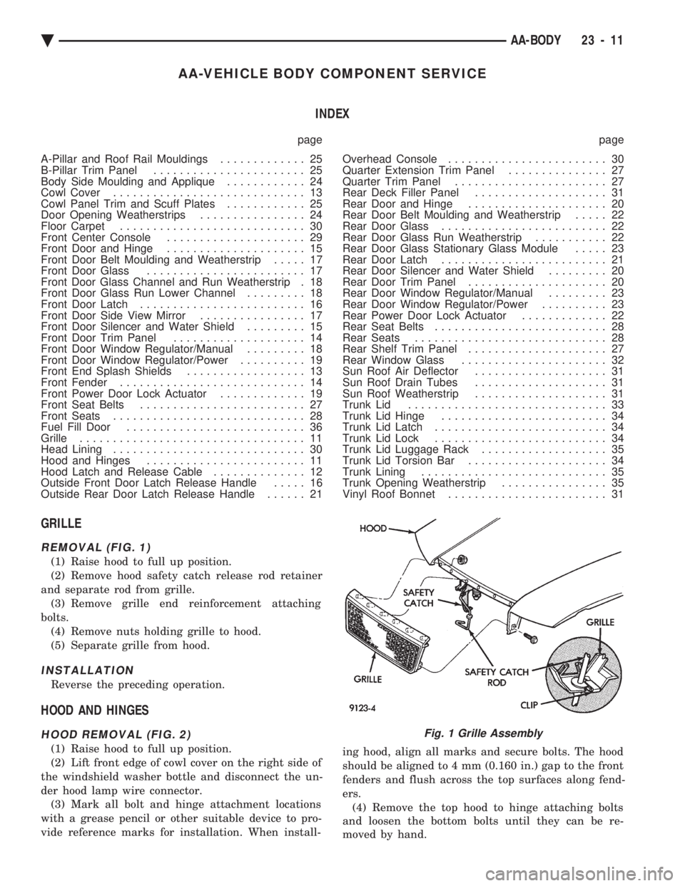
GRILLE
REMOVAL (FIG. 1)
(1) Raise hood to full up position.
(2) Remove hood safety catch release rod retainer
and separate rod from grille. (3) Remove grille end reinforcement attaching
bolts. (4) Remove nuts holding grille to hood.
(5) Separate grille from hood.
INSTALLATION
Reverse the preceding operation.
HOOD AND HINGES
HOOD REMOVAL (FIG. 2)
(1) Raise hood to full up position.
(2) Lift front edge of cowl cover on the right side of
the windshield washer bottle and disconnect the un-
der hood lamp wire connector. (3) Mark all bolt and hinge attachment locations
with a grease pencil or other suitable device to pro-
vide reference marks for installation. When install- ing hood, align all marks and secure bolts. The hood
should be aligned to 4 mm (0.160 in.) gap to the front
fenders and flush across the top surfaces along fend-
ers. (4) Remove the top hood to hinge attaching bolts
and loosen the bottom bolts until they can be re-
moved by hand.
Fig. 1 Grille Assembly
Ä AA-BODY 23 - 11
Page 2190 of 2438
bottom trunk lid to hinge attaching bolts. Separate
the trunk lid from the vehicle.
INSTALLATION
Reverse the preceding operation.
TRUNK LID HINGE
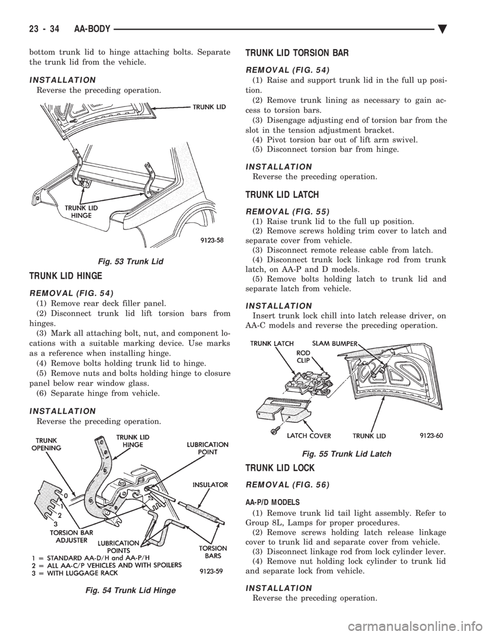
REMOVAL (FIG. 54)
(1) Remove rear deck filler panel.
(2) Disconnect trunk lid lift torsion bars from
hinges. (3) Mark all attaching bolt, nut, and component lo-
cations with a suitable marking device. Use marks
as a reference when installing hinge. (4) Remove bolts holding trunk lid to hinge.
(5) Remove nuts and bolts holding hinge to closure
panel below rear window glass. (6) Separate hinge from vehicle.
INSTALLATION
Reverse the preceding operation.
TRUNK LID TORSION BAR
REMOVAL (FIG. 54)
(1) Raise and support trunk lid in the full up posi-
tion. (2) Remove trunk lining as necessary to gain ac-
cess to torsion bars. (3) Disengage adjusting end of torsion bar from the
slot in the tension adjustment bracket. (4) Pivot torsion bar out of lift arm swivel.
(5) Disconnect torsion bar from hinge.
INSTALLATION
Reverse the preceding operation.
TRUNK LID LATCH
REMOVAL (FIG. 55)
(1) Raise trunk lid to the full up position.
(2) Remove screws holding trim cover to latch and
separate cover from vehicle. (3) Disconnect remote release cable from latch.
(4) Disconnect trunk lock linkage rod from trunk
latch, on AA-P and D models. (5) Remove bolts holding latch to trunk lid and
separate latch from vehicle.
INSTALLATION
Insert trunk lock chill into latch release driver, on
AA-C models and reverse the preceding operation.
TRUNK LID LOCK
REMOVAL (FIG. 56)
AA-P/D MODELS
(1) Remove trunk lid tail light assembly. Refer to
Group 8L, Lamps for proper procedures. (2) Remove screws holding latch release linkage
cover to trunk lid and separate cover from vehicle. (3) Disconnect linkage rod from lock cylinder lever.
(4) Remove nut holding lock cylinder to trunk lid
and separate lock from vehicle.
INSTALLATION
Reverse the preceding operation.
Fig. 53 Trunk Lid
Fig. 54 Trunk Lid Hinge
Fig. 55 Trunk Lid Latch
23 - 34 AA-BODY Ä
Page 2191 of 2438
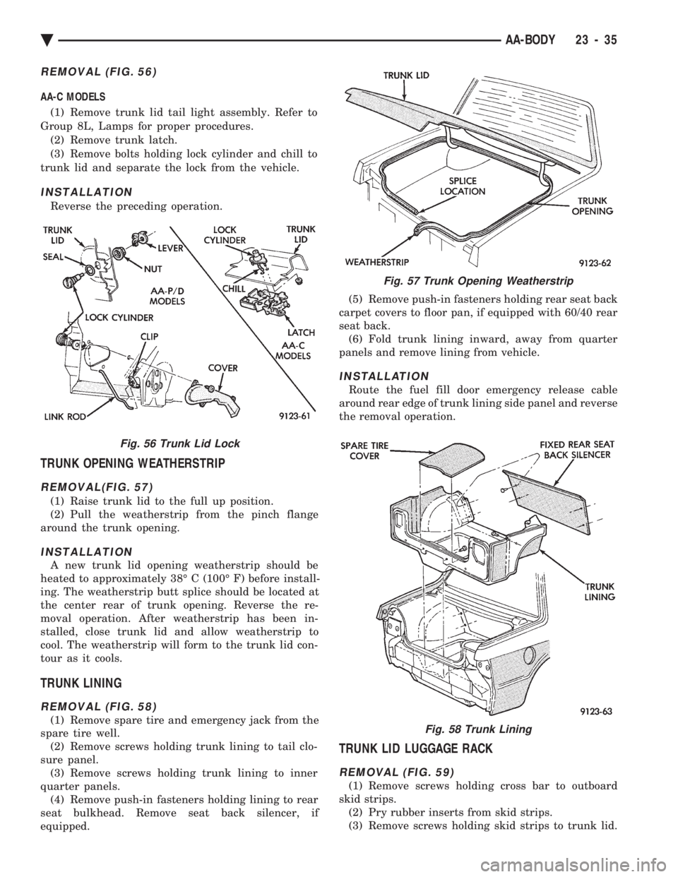
REMOVAL (FIG. 56)
AA-C MODELS (1) Remove trunk lid tail light assembly. Refer to
Group 8L, Lamps for proper procedures. (2) Remove trunk latch.
(3) Remove bolts holding lock cylinder and chill to
trunk lid and separate the lock from the vehicle.
INSTALLATION
Reverse the preceding operation.
TRUNK OPENING WEATHERSTRIP
REMOVAL(FIG. 57)
(1) Raise trunk lid to the full up position.
(2) Pull the weatherstrip from the pinch flange
around the trunk opening.
INSTALLATION
A new trunk lid opening weatherstrip should be
heated to approximately 38É C (100É F) before install-
ing. The weatherstrip butt splice should be located at
the center rear of trunk opening. Reverse the re-
moval operation. After weatherstrip has been in-
stalled, close trunk lid and allow weatherstrip to
cool. The weatherstrip will form to the trunk lid con-
tour as it cools.
TRUNK LINING
REMOVAL (FIG. 58)
(1) Remove spare tire and emergency jack from the
spare tire well. (2) Remove screws holding trunk lining to tail clo-
sure panel. (3) Remove screws holding trunk lining to inner
quarter panels. (4) Remove push-in fasteners holding lining to rear
seat bulkhead. Remove seat back silencer, if
equipped. (5) Remove push-in fasteners holding rear seat back
carpet covers to floor pan, if equipped with 60/40 rear
seat back. (6) Fold trunk lining inward, away from quarter
panels and remove lining from vehicle.
INSTALLATION
Route the fuel fill door emergency release cable
around rear edge of trunk lining side panel and reverse
the removal operation.
TRUNK LID LUGGAGE RACK
REMOVAL (FIG. 59)
(1) Remove screws holding cross bar to outboard
skid strips. (2) Pry rubber inserts from skid strips.
(3) Remove screws holding skid strips to trunk lid.
Fig. 56 Trunk Lid Lock
Fig. 57 Trunk Opening Weatherstrip
Fig. 58 Trunk Lining
Ä AA-BODY 23 - 35
Page 2193 of 2438
AC-VEHICLE BODY COMPONENT SERVICE INDEX
page page
A-Pillar and Roof Rail Mouldings ............. 46
B-Pillar Trim Panel ....................... 46
Body Mouldings .......................... 49
Cowl Panel Trim and Scuff Plates ............ 46
Door Frame Trim Moulding ................. 41
Front Door and Hinge ..................... 41
Front Door Glass ........................ 43
Front Door Latch ......................... 42
Front Door Trim Panel .................... 40
Front Door Water Shield ................... 41
Front Door Window Regulator ............... 42
Front End Splash Shields .................. 40
Front Seat Belts ......................... 47
Front Seats ............................. 48
Grille AC/C Body ......................... 38
Grille AC/D or AC/C-H Body ................ 37
Grille Extension Moulding .................. 37
Grille Opening Panel AC/C-Body ............. 38
Grille Opening Panel AC/D and AC/C-H Body . . . 37
Head Lining ............................. 45
Hood and Hinges ........................ 38
Hood Latch and Release Cable .............. 39
Hood Latch Release Cable ................. 39 Hood Ornament AC/C
..................... 38
Outside Door Handle ...................... 42
Overhead Console ........................ 45
Quarter Trim Panel ....................... 46
Rear Deck Filler Panel .................... 49
Rear Door and Hinge ..................... 44
Rear Door Frame Trim Moulding ............. 43
Rear Door Glass ......................... 45
Rear Door Glass Lift Plate and Guide Bar ..... 45
Rear Door Latch ......................... 44
Rear Door Outside Handle ................. 44
Rear Door Silencer and Water Shield ......... 43
Rear Door Trim Panel ..................... 43
Rear Door Window Regulator ............... 45
Rear Seat Belts .......................... 47
Rear Seats ............................. 49
Rear Shelf Trim Panel ..................... 47
Rear Window Glass ...................... 50
Side View Mirror Trim Cover ................ 41
Trunk Lid .............................. 50
Trunk Lid Hinge ......................... 51
Trunk Lid Torsion Bar ..................... 51
Vinyl Roof Bonnet ........................ 49
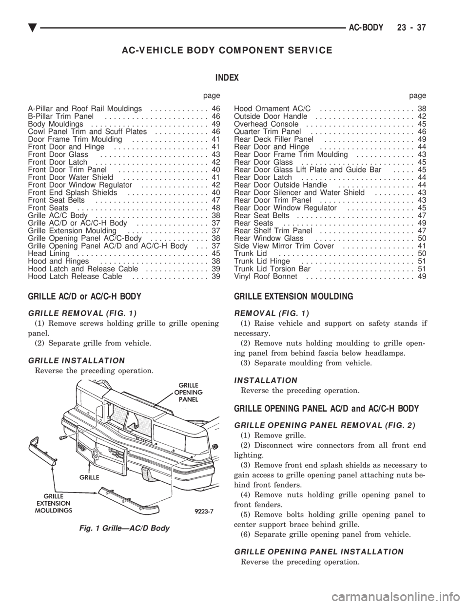
GRILLE AC/D or AC/C-H BODY
GRILLE REMOVAL (FIG. 1)
(1) Remove screws holding grille to grille opening
panel. (2) Separate grille from vehicle.
GRILLE INSTALLATION
Reverse the preceding operation.
GRILLE EXTENSION MOULDING
REMOVAL (FIG. 1)
(1) Raise vehicle and support on safety stands if
necessary. (2) Remove nuts holding moulding to grille open-
ing panel from behind fascia below headlamps. (3) Separate moulding from vehicle.
INSTALLATION
Reverse the preceding operation.
GRILLE OPENING PANEL AC/D and AC/C-H BODY
GRILLE OPENING PANEL REMOVAL (FIG. 2)
(1) Remove grille.
(2) Disconnect wire connectors from all front end
lighting. (3) Remove front end splash shields as necessary to
gain access to grille opening panel attaching nuts be-
hind front fenders. (4) Remove nuts holding grille opening panel to
front fenders. (5) Remove bolts holding grille opening panel to
center support brace behind grille. (6) Separate grille opening panel from vehicle.
GRILLE OPENING PANEL INSTALLATION
Reverse the preceding operation.
Fig. 1 GrilleÐAC/D Body
Ä AC-BODY 23 - 37