CHEVROLET SILVERADO 2011 2.G Owners Manual
Manufacturer: CHEVROLET, Model Year: 2011, Model line: SILVERADO, Model: CHEVROLET SILVERADO 2011 2.GPages: 588, PDF Size: 7.99 MB
Page 411 of 588
Black plate (117,1)Chevrolet Silverado Owner Manual - 2011
Driving and Operating 9-117
StabiliTrak systems to activate,
power sent to the trailer's brakes
will be automatically adjusted to
minimize trailer wheel lock-up.
This does not imply that the trailer
has StabiliTrak.
2500 and 3500 series vehicles with
StabiliTrak have a Trailer Sway
Control (TSC) feature. SeeTrailer
Sway Control (TSC) on page 9‑123.
2500 and 3500 series vehicles
with StabiliTrak have a Hill Start
Assist (HSA) feature. See Hill Start
Assist (HSA) on page 9‑70.
If the vehicle’s brake, antilock
brake, or StabiliTrak systems are
not functioning properly, the ITBC
system may not be fully functional
or may not function at all. Make
sure all of these systems are
fully operational to ensure full
functionality of the ITBC system.
The ITBC system is powered
through the vehicle's electrical
system. Turning the ignition off
will also turn off the ITBC system. The ITBC system is fully functional
only when the ignition is in ON or
in RUN.
The ITBC system can only be used
with trailers with electric brakes.
{WARNING
Connecting a trailer that is not
compatible with the ITBC system
may result in reduced or complete
loss of trailer braking. There may
be an increase in stopping
distance or trailer instability which
could result in personal injury or
damage to the vehicle, trailer,
or other property. An aftermarket
controller may be available for
use with trailers with surge, air,
or electric‐over‐hydraulic trailer
brake systems. To determine the
type of brakes on the trailer and
the availability of controllers,
check with your trailer
manufacturer or dealer.
When trailering, make sure of the
following:
.The ITBC system is used only
with trailers that are equipped
with electric brakes.
.All applicable local and federal
laws and regulations are
followed.
.All electrical and mechanical
connections to the trailer are
made correctly.
.The trailer
’s brakes are in proper
working condition.
.The trailer and vehicle are
properly loaded for the towing
condition.
The ITBC system is a
factory-installed item. Out‐of‐factory
installation of this system should not
be attempted. GM is not responsible
for warranty or performance of the
system resulting from out‐of‐factory
installation.
Page 412 of 588
Black plate (118,1)Chevrolet Silverado Owner Manual - 2011
9-118 Driving and Operating
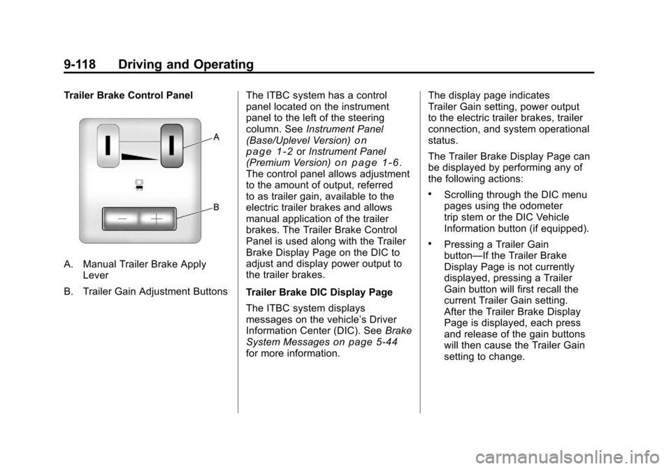
Trailer Brake Control Panel
A. Manual Trailer Brake ApplyLever
B. Trailer Gain Adjustment Buttons The ITBC system has a control
panel located on the instrument
panel to the left of the steering
column. See
Instrument Panel
(Base/Uplevel Version)
on
page 1‑2or Instrument Panel
(Premium Version)on page 1‑6.
The control panel allows adjustment
to the amount of output, referred
to as trailer gain, available to the
electric trailer brakes and allows
manual application of the trailer
brakes. The Trailer Brake Control
Panel is used along with the Trailer
Brake Display Page on the DIC to
adjust and display power output to
the trailer brakes.
Trailer Brake DIC Display Page
The ITBC system displays
messages on the vehicle’s Driver
Information Center (DIC). See Brake
System Messages
on page 5‑44for more information. The display page indicates
Trailer Gain setting, power output
to the electric trailer brakes, trailer
connection, and system operational
status.
The Trailer Brake Display Page can
be displayed by performing any of
the following actions:
.Scrolling through the DIC menu
pages using the odometer
trip stem or the DIC Vehicle
Information button (if equipped).
.Pressing a Trailer Gain
button—If the Trailer Brake
Display Page is not currently
displayed, pressing a Trailer
Gain button will first recall the
current Trailer Gain setting.
After the Trailer Brake Display
Page is displayed, each press
and release of the gain buttons
will then cause the Trailer Gain
setting to change.
Page 413 of 588
Black plate (119,1)Chevrolet Silverado Owner Manual - 2011
Driving and Operating 9-119
.Activating the Manual Trailer
Brake Apply lever.
.Connecting a trailer equipped
with electric trailer brakes.
All DIC warning and service
messages must first be
acknowledged by the driver
by pressing the odometer trip stem
or the DIC Vehicle Information
button (if equipped) before the
Trailer Brake Display Page can
be displayed and Trailer Gain
can be adjusted.
TRAILER GAIN: This setting is
displayed any time the Trailer Brake
Display Page is active. This setting
can be adjusted from 0.0 to 10.0
with either a trailer connected or
disconnected. To adjust the Trailer
Gain, press one of the Trailer Gain
adjustment buttons located on the
Trailer Brake Control Panel. Press
and hold a gain button to cause the
Trailer Gain to continuously adjust.
To turn the output to the trailer off,
adjust the Trailer Gain setting to
0.0 (zero). 0.0 (zero) gain is the factory default
setting. To properly adjust trailer
gain, see
“Trailer Gain Adjustment
Procedure” later in this section.
TRAILER OUTPUT: This is
displayed any time a trailer with
electric brakes is connected. Output
to the electric brakes is based on
the amount of vehicle braking
present and relative to the Trailer
Gain setting. Output is displayed
from 0 to 10 bars for each gain
setting.
On vehicles with Trailer Sway
Control (TSC) or Hill Start Assist
(HSA), output to the electric trailer
brakes may be displayed when the
systems are active. See Trailer
Sway Control (TSC)
on page 9‑123and Hill Start Assist (HSA)on
page 9‑70. The Trailer Output will indicate
“- - - - - -”
on the Trailer Brake
Display Page whenever the
following occur:
.No trailer is connected
.A trailer without electric brakes
is connected (no DIC message
is displayed)
.A trailer with electric brakes
has become disconnected
(a CHECK TRAILER WIRING
message will also be displayed
on the DIC)
.There is a fault present in the
wiring to the electric trailer
brakes (a CHECK TRAILER
WIRING message will also be
displayed on the DIC)
.There is a fault in the ITBC
system (a SERVICE TRAILER
BRAKE SYSTEM message will
also be displayed in the DIC)
Page 414 of 588
Black plate (120,1)Chevrolet Silverado Owner Manual - 2011
9-120 Driving and Operating
Manual Trailer Brake Apply
The Manual Trailer Brake Apply
Lever is located on the Trailer
Brake Control Panel and is used to
apply the trailer’s electric brakes
independent of the vehicle’s brakes.
This lever is used in the Trailer Gain
Adjustment Procedure to properly
adjust the power output to the trailer
brakes. Sliding the lever to the left
will apply only the trailer brakes.
The power output to the trailer is
indicated in the Trailer Brake
Display Page on the DIC. If the
vehicle’s service brakes are applied
while using the Manual Trailer Brake
Apply Lever, the trailer output power
will be the greater of the two.
The trailer's and the vehicle's brake
lamps will come on when either
vehicle braking or manual trailer
brakes are applied. Trailer Gain Adjustment Procedure
Trailer Gain should be set for a
specific trailering condition and
must be adjusted any time vehicle
loading, trailer loading, or road
surface conditions change.
Setting the Trailer Gain properly is
needed for the best trailer stopping
performance. A trailer that is
over-gained may result in locked
trailer brakes. A trailer that is
under-gained may result in not
enough trailer braking. Both of
these conditions may result in
poorer stopping and stability of
the vehicle and trailer.
Use the following procedure to
correctly adjust Trailer Gain for
each towing condition:
1. Make sure the trailer brakes are
in proper working condition.
2. Connect a properly loaded trailer to the vehicle and make
all necessary mechanical
and electrical connections.
See Vehicle Load Limits
on
page 9‑23for more information.
3. After the electrical connection is made to a trailer equipped with
electric brakes:
.A TRAILER CONNECTED
message will be briefly
displayed on the DIC.
.The Trailer Brake Display
Page will appear on the
DIC showing TRAILER
GAIN and TRAILER
OUTPUT.
Page 415 of 588
Black plate (121,1)Chevrolet Silverado Owner Manual - 2011
Driving and Operating 9-121
.In the Trailer Output display
on the DIC,“- - - - - -”will
disappear if there is no
error present. Connecting
a trailer without electric
brakes will not clear the
six dashed lines.
4. Adjust the Trailer Gain by using the gain adjustment (+ / -)
buttons on the Trailer Brake
Control Panel.
5. Drive the vehicle with the trailer attached on a level road surface
representative of the towing
condition and free of traffic at
about 32 to 40 km/h (20 to
25 mph) and fully apply the
Manual Trailer Brake Apply
Lever.
Adjusting trailer gain at speeds
lower than 32 to 40 km/h
(20 to 25 mph) may result
in an incorrect gain setting. 6. Adjust the Trailer Gain to just
below the point of trailer wheel
lock-up, indicated by trailer
wheel squeal or tire smoke
when a trailer wheel locks.
Trailer wheel lock-up may not
occur if towing a heavily loaded
trailer. In this case, adjust the
Trailer Gain to the highest
allowable setting for the towing
condition.
7. Re-adjust Trailer Gain any time vehicle loading, trailer loading or
road surface conditions change
or if trailer wheel lock-up is
noticed at any time while towing.
Other ITBC-Related DIC Messages
In addition to displaying TRAILER
GAIN and TRAILER OUTPUT
through the DIC, trailer connection
and ITBC system status are
displayed on the DIC.
TRAILER CONNECTED: This
message will be briefly displayed
when a trailer with electric brakes
is first connected to the vehicle. This message will automatically turn
off in about 10 seconds. The driver
can also acknowledge this message
before it automatically turns off.
CHECK TRAILER WIRING: This
message will be displayed if:
1. The ITBC system first
determines connection to a
trailer with electric brakes and
then the trailer harness becomes
disconnected from the vehicle.
If the disconnect occurs while
the vehicle is stationary, this
message will automatically
turn off in about 30 seconds.
This message will also turn off if
the driver acknowledges this
message or if the trailer harness
is re-connected.
If the disconnect occurs while
the vehicle is moving, this
message will continue until
the ignition is turned off.
This message will also turn
off if the driver acknowledges
this message or if the trailer
harness is re-connected.
Page 416 of 588
Black plate (122,1)Chevrolet Silverado Owner Manual - 2011
9-122 Driving and Operating
2. There is an electrical fault inthe wiring to the electric trailer
brakes. This message will
continue as long as there is
an electrical fault in the trailer
wiring. This message will
also turn off if the driver
acknowledges this message.
To determine if the electrical
fault is on the vehicle side or trailer
side of the trailer wiring harness
connection, do the following:
1. Disconnect the trailer wiring harness from the vehicle.
2. Turn the ignition off.
3. Wait 10 seconds, then turn the ignition back to RUN. 4. If the CHECK TRAILER WIRING
message re-appears, the
electrical fault is on the
vehicle side.
If the CHECK TRAILER WIRING
message only re-appears when
connecting the trailer wiring
harness to the vehicle, the
electrical fault is on the
trailer side.
SERVICE TRAILER BRAKE
SYSTEM: This message will
be displayed when there is a
problem with the ITBC system.
If this message persists over
multiple ignition cycles, there is
a problem with the ITBC system.
Take the vehicle to an authorized
GM dealer to have the ITBC system
diagnosed and repaired. If either the CHECK TRAILER
WIRING or SERVICE TRAILER
BRAKE SYSTEM message is
displayed while driving the vehicle,
power is no longer available to
the trailer brakes. When traffic
conditions allow, carefully pull the
vehicle over to the side of the road
and turn the ignition off. Check the
wiring connection to the trailer and
turn the ignition back on. If either of
these messages continues, either
the vehicle or trailer needs service.
An authorized GM dealer may
be able to diagnose and repair
problems with the trailer. However,
any diagnosis and repair of the
trailer is not covered under the
vehicle warranty. Please contact
your trailer dealer for assistance
with trailer repairs and trailer
warranty information.
Page 417 of 588
Black plate (123,1)Chevrolet Silverado Owner Manual - 2011
Driving and Operating 9-123
Trailer Sway
Control (TSC)
Trailer Sway Control (TSC)
2500 and 3500 series vehicles with
StabiliTrak have a Trailer Sway
Control (TSC) feature. If the vehicle
is towing a trailer and the system
detects that the trailer is swaying,
the vehicle's brakes are applied
without the driver pressing the brake
pedal. If the vehicle is equipped with
the Integrated Trailer Brake Control
(ITBC) system, StabiliTrak may also
apply the trailer brakes. The TCS/
StabiliTrak warning light will flash on
the instrument panel cluster to notify
the driver to reduce speed. If the
trailer continues to sway, StabiliTrak
will reduce engine torque to help
slow the vehicle.
Adding non‐dealer/non‐retailer
accessories can affect the vehicle's
performance. SeeAccessories and
Modifications
on page 10‑3for
more information.
Conversions and
Add-Ons
Add-On Electrical
Equipment
Notice: Do not add anything
electrical to the vehicle unless
you check with your dealer first.
Some electrical equipment can
damage the vehicle and the
damage would not be covered
by the vehicle's warranty. Some
add-on electrical equipment can
keep other components from
working as they should.
Add-on equipment can drain the
vehicle 12‐volt battery, even if the
vehicle is not operating.
The vehicle has an airbag system.
Before attempting to add anything
electrical to the vehicle, see
Servicing the Airbag-Equipped
Vehicle
on page 3‑48and Adding
Equipment to the Airbag-Equipped
Vehicle on page 3‑48.
Adding a Snow Plow or
Similar Equipment
Before installing a snow plow on the
vehicle, here are some things you
need to know:
Notice: If your vehicle does
not have the snow plow prep
package, adding a plow can
damage your vehicle, and the
repairs would not be covered by
warranty. Unless your vehicle was
built to carry a snow plow, do not
add one to your vehicle. If your
vehicle has the snow plow prep
package, called RPO VYU, then
the payload your vehicle can
carry will be reduced when a
snow plow is installed. Your
vehicle can be damaged if either
the front or rear axle ratings or
the Gross Vehicle Weight (GVW)
are exceeded.
Some vehicles are built with a
special snow plow prep package,
called RPO VYU. If your vehicle has
this option, you can add a plow to it,
provided certain weights, such as
Page 418 of 588
Black plate (124,1)Chevrolet Silverado Owner Manual - 2011
9-124 Driving and Operating
the weights on the vehicle's
axles and the Gross Vehicle
Weight (GVW), are not exceeded.
The plow the vehicle can carry
depends on many things, such as:
.The options the vehicle came
with, and the weight of those
options.
.The weight and number of
passengers you intend to carry.
.The weight of items added to
the vehicle, like a tool box or
truck cap.
.The total weight of any
additional cargo you intend to
carry.
Say, for example, you have a 318 kg
(700 lb) snow plow. The total weight
of all occupants and cargo inside
the cab should not exceed 135 kg
(300 lb). This means that you may
only be able to carry one passenger.
But, even this may be too much
if you have got other equipment
already adding to the weight of
the vehicle. Here are some guidelines for safely
carrying a snow plow on the vehicle:
.Make sure the weight on the
front and rear axles does not
exceed the axle rating for each.
.For the front axle, if more cargo
or passengers must be carried,
appropriate counter ballast must
be installed rear of the rear axle.
Counter ballast must be properly
secured so it will not move
during driving.
.Follow the snow
plow manufacturer's
recommendations regarding
rear ballast. Rear ballast may
be required to ensure a proper
front and rear weight distribution
ratio, even though the actual
weight at the front axle may be
less than the front axle rating.
.The snow plow manufacturer
or installer can assist you in
determining the amount of rear
ballast required, to help make
sure the snowplow/vehicle
combination does not exceed
the GVW rating, the front and
rear axle ratings, and the front
and rear weight distribution ratio.
.The total vehicle must not
exceed the GVW rating.
Front axle reserve capacity is the
difference between the Gross Axle
Weight Rating (GAWR) and the front
axle weight of the vehicle with full
fuel and passengers. Basically, it is
the amount of weight that can be
added to the front axle before
reaching the front GAWR.
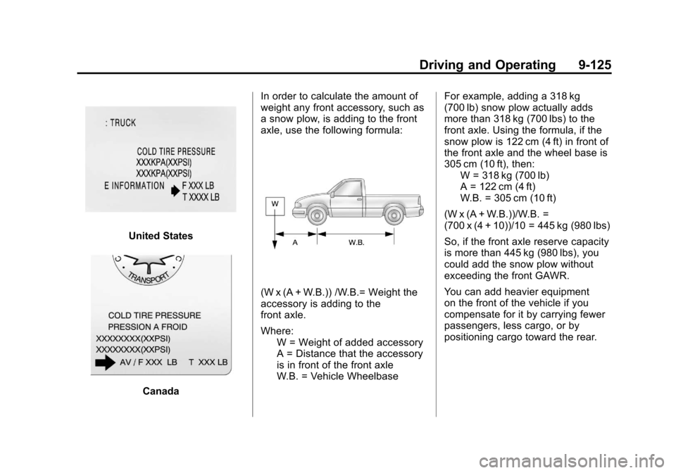
The front axle reserve capacity
for the vehicle can be found
in the lower right corner of the
Certification/Tire label, as shown.
Page 419 of 588
Black plate (125,1)Chevrolet Silverado Owner Manual - 2011
Driving and Operating 9-125
United States
CanadaIn order to calculate the amount of
weight any front accessory, such as
a snow plow, is adding to the front
axle, use the following formula:
(W x (A + W.B.)) /W.B.= Weight the
accessory is adding to the
front axle.
Where:
W = Weight of added accessory
A = Distance that the accessory
is in front of the front axle
W.B. = Vehicle Wheelbase For example, adding a 318 kg
(700 lb) snow plow actually adds
more than 318 kg (700 lbs) to the
front axle. Using the formula, if the
snow plow is 122 cm (4 ft) in front of
the front axle and the wheel base is
305 cm (10 ft), then:
W = 318 kg (700 lb)
A = 122 cm (4 ft)
W.B. = 305 cm (10 ft)
(W x (A + W.B.))/W.B. =
(700 x (4 + 10))/10 = 445 kg (980 lbs)
So, if the front axle reserve capacity
is more than 445 kg (980 lbs), you
could add the snow plow without
exceeding the front GAWR.
You can add heavier equipment
on the front of the vehicle if you
compensate for it by carrying fewer
passengers, less cargo, or by
positioning cargo toward the rear.
Page 420 of 588
Black plate (126,1)Chevrolet Silverado Owner Manual - 2011
9-126 Driving and Operating
This has the effect of reducing the
load on the front. However, the front
GAWR, rear GAWR, and the Gross
Vehicle Weight Rating (GVWR) must
never be exceeded.
{WARNING
On some vehicles that have
certain front mounted equipment,
such as a snow plow, it may be
possible to load the front axle to
the front gross axle weight rating
(GAWR) but not have enough
weight on the rear axle to have
proper braking performance.
If your brakes can not work
properly, you could have a crash.
To help your brakes work properly
when a snow plow is installed,
always follow the snow plow
manufacturer or installer's
recommendation for rear ballast
to ensure a proper front and rear
weight distribution ratio, even
though the actual front weight(Continued)
WARNING (Continued)
may be less than the front
GAWR, and the total vehicle
weight is less than the gross
vehicle weight rating (GVWR).
Maintaining a proper front and
rear weight distribution ratio is
necessary to provide proper
braking performance.
Total vehicle reserve capacity is the
difference between the GVWR and
the weight of the truck with full fuel
and passengers. It is the amount
of weight that can be added to the
vehicle before reaching the GVWR.
Keep in mind that reserve capacity
numbers are intended as a guide
when selecting the amount of
equipment or cargo the truck can
carry. If unsure of the vehicle's front,
rear, or total weight, go to a weigh
station and weigh the vehicle. Your
dealer can also help with this. The total vehicle reserve capacity
for the vehicle can be found
in the lower right corner of the
Certification/Tire label as shown
previously.
See your dealer for additional
advice and information about
using a snow plow on the vehicle.
Also, see
Vehicle Load Limits
on
page 9‑23.
Emergency Roof Lamp
Provisions
Vehicles with the RPO VYU snow
plow prep package also have an
emergency roof lamp provision
package, RPO TRW. Wiring for the
emergency roof lamp is provided
above the overhead console. See
Auxiliary Roof-Mounted Lamp
on
page 6‑7for switch location.