light CHEVROLET TAHOE 2011 3.G Owner's Manual
[x] Cancel search | Manufacturer: CHEVROLET, Model Year: 2011, Model line: TAHOE, Model: CHEVROLET TAHOE 2011 3.GPages: 98, PDF Size: 1.55 MB
Page 68 of 98
Black plate (20,1)Chevrolet Tahoe and GMC Yukon/Yukon Denali Hybrid - 2011
10-20 Vehicle Care
.One or more TPMS sensors are
missing or damaged. The DIC
message and the TPMS
malfunction light should go off
when the TPMS sensors are
installed and the sensor
matching process is performed
successfully. See your dealer for
service.
.Replacement tires or wheels do
not match your vehicle's original
equipment tires or wheels. Tires
and wheels other than those
recommended for your vehicle
could prevent the TPMS from
functioning properly. See
“Buying New Tires”in the owner
manual.
.Operating electronic devices or
being near facilities using radio
wave frequencies similar to the
TPMS could cause the TPMS
sensors to malfunction.
If the TPMS is not functioning it
cannot detect or signal a low tire
condition. See your dealer for service if the TPMS malfunction
light and DIC message comes on
and stays on.
TPMS Sensor Matching
Process
Each TPMS sensor has a unique
identification code. Any time you
rotate your vehicle's tires or replace
one or more of the TPMS sensors,
the identification codes will need to
be matched to the new tire/wheel
position. The sensors are matched
to the tire/wheel positions in the
following order: driver side front tire,
passenger side front tire, passenger
side rear tire, and driver side rear
tire using a TPMS diagnostic tool.
See your dealer for service.
The TPMS sensors can also be
matched to each tire/wheel position
by increasing or decreasing the
tire's air pressure. If increasing the
tire's air pressure, do not exceed
the maximum inflation pressure
indicated on the tire's sidewall.
To decrease air-pressure out of a
tire you can use the pointed end of
the valve cap, a pencil-style air
pressure gauge, or a key.
You have two minutes to match
the first tire/wheel position, and
five minutes overall to match all four
tire/wheel positions. If it takes longer
than two minutes, to match the first
tire and wheel, or more than
five minutes to match all four tire
and wheel positions the matching
process stops and you need to
start over.
The TPMS sensor matching process
is outlined below:
1. Set the parking brake.
2. Turn the ignition switch to ON/
RUN with the engine off.
3. Press
QandKon the Remote
Keyless Entry (RKE) transmitter
at the same time for
approximately five seconds. The
horn sounds twice to signal the
receiver is in relearn mode and
Page 70 of 98
Black plate (22,1)Chevrolet Tahoe and GMC Yukon/Yukon Denali Hybrid - 2011
10-22 Vehicle Care
After the tires have been
rotated, adjust the front and rear
inflation pressures as shown on
the Tire and Loading Information
label. See“Vehicle Load Limits”
in the owner manual for an
example of the label and its
location on your vehicle.
The Tire Pressure Monitor
System (TPMS) sensors will
need to be reset after a tire
rotation. See “TPMS Sensor
Identification Codes” under“Tire
Pressure Monitor Operation”.
Make certain that all wheel nuts
are properly tightened. See
“Wheel Nut Torque” under
“Capacities and Specifications ”
in the owner manual.
Lightly coat the center of the
wheel hub with wheel bearing
grease after a wheel change or
tire rotation to prevent corrosion
or rust build-up. Do not get grease on the flat wheel
mounting surface or on the
wheel nuts or bolts.
Tire Chains
{WARNING
Do not use tire chains. There is
not enough clearance. Tire chains
used on a vehicle without the
proper amount of clearance can
cause damage to the brakes,
suspension, or other vehicle
parts. The area damaged by the
tire chains could cause you to
lose control of the vehicle and
you or others may be injured in a
crash. Use another type of
traction device only if its
manufacturer recommends it for
use on the vehicle and tire size
combination and road conditions.
Follow that manufacturer's
instructions. To help avoid
(Continued)
WARNING (Continued)
damage to the vehicle, drive
slowly, re‐adjust or remove the
device if it is contacting the
vehicle, and do not spin the
wheels. If you do find traction
devices that will fit, install them on
the rear tires.
If a Tire Goes Flat
Your vehicle has a tire inflator kit.
There is no spare tire, no tire
changing equipment, and no place
to store a tire.
It is unusual for a tire to blow out
while you are driving, especially if
you maintain your tires properly.
If air goes out of a tire, it is much
more likely to leak out slowly. But,
if you should ever have a blow out,
here are a few tips about what to
expect and what to do:
If a front tire fails, the flat tire
creates a drag that pulls the vehicle
toward that side. Take your foot off
Page 74 of 98

Black plate (26,1)Chevrolet Tahoe and GMC Yukon/Yukon Denali Hybrid - 2011
10-26 Vehicle Care
If a tire goes flat, avoid further tire
and wheel damage by driving slowly
to a level place. Turn on the hazard
warning flashers.
SeeIf a Tire Goes Flat on
page 10‑22 for other important
safety warnings.
Do not remove any objects that
have penetrated the tire.
1. Remove the tire sealant and compressor kit from its storage
location. See Storing the Tire
Sealant and Compressor Kit on
page 10‑31.
Make sure the on/off button (D)
is in the off (O) position.
2. Unwrap the sealant/air hose (G) and the power plug (C).
3. Place the kit on the ground. Make sure the tire valve stem is
positioned close to the ground
so the hose will reach it.
4. Remove the valve stem cap from the flat tire by turning it
counterclockwise. 5. Attach the sealant/air hose (G)
onto the tire valve stem. Turn it
clockwise until it is tight.
6. Plug the power plug (C) into the accessory power outlet in the
vehicle. Unplug all items from
other accessory power outlets.
See “Power Outlets” in the
owner manual.
If the vehicle has an accessory
power outlet, do not use the
cigarette lighter.
If the vehicle only has a cigarette
lighter, use the cigarette lighter.
Do not pinch the power plug
cord in the door or window.
7. Start the vehicle. The vehicle must be running while using the
air compressor.
8. Press the on/off (D) button to turn the tire sealant and
compressor kit on.
The compressor will inject
sealant and air into the tire. The pressure gauge (E) will
initially show a high pressure
while the compressor pushes the
sealant into the tire. Once the
sealant is completely dispersed
into the tire, the pressure will
quickly drop and start to rise
again as the tire inflates with
air only.
9. Inflate the tire to the recommended inflation pressure
using the pressure gauge (E).
The recommended inflation
pressure can be found on the
Tire and Loading Information
label. See Tire Pressure on
page 10‑17.
The pressure gauge (E) may
read higher than the actual tire
pressure while the compressor is
on. Turn the compressor off to
get an accurate pressure
reading. The compressor may
be turned on/off until the correct
pressure is reached.
Page 77 of 98

Black plate (29,1)Chevrolet Tahoe and GMC Yukon/Yukon Denali Hybrid - 2011
Vehicle Care 10-29
7. Attach the air only hose (F) ontothe tire valve stem and press the
lever down to secure it.
8. Plug the power plug (C) into the accessory power outlet in the
vehicle. Unplug all items from
other accessory power outlets.
See “Power Outlets” in the
owner manual.
If the vehicle has an accessory
power outlet, do not use the
cigarette lighter.
If the vehicle only has a cigarette
lighter, use the cigarette lighter.
Do not pinch the power plug
cord in the door or window.
9. Start the vehicle. The vehicle must be running while using the
air compressor. 10. Press the on/off (D) button to
turn the compressor on.
The compressor will inflate the
tire with air only.
11. Inflate the tire to the recommended inflation
pressure using the pressure
gauge (E). The recommended
inflation pressure can be found
on the Tire and Loading
Information label. See Tire
Pressure on page 10‑17.
The pressure gauge (E) may
read higher than the actual tire
pressure while the compressor
is on. Turn the compressor off
to get an accurate reading. The
compressor may be turned on/
off until the correct pressure is
reached. 12. Press the on/off button (D) to
turn the tire sealant and
compressor kit off.
Be careful while handling the
tire sealant and compressor kit
as it could be warm after
usage.
13. Unplug the power plug (C) from the accessory power outlet in
the vehicle.
14. Disconnect the air only hose (C) from the tire valve
stem, by turning it
counterclockwise, and replace
the tire valve stem cap.
15. Replace the air only hose (F) and the power plug (C) back in
its original location.
16. Place the equipment in the original storage location in the
vehicle.
Page 81 of 98
Black plate (33,1)Chevrolet Tahoe and GMC Yukon/Yukon Denali Hybrid - 2011
Vehicle Care 10-33
2. Get the vehicles close enoughso the jumper cables can reach,
but be sure the vehicles are not
touching each other. It could
cause a ground connection you
do not want. You would not be
able to start your vehicle, and
the bad grounding could damage
the electrical systems.
To avoid the possibility of the
vehicles rolling, set the parking
brake firmly on both vehicles
involved in the jump start
procedure. Put the automatic
transmission in P (Park) or a
manual transmission in
N (Neutral) before setting the
parking brake. If you have a
four-wheel-drive vehicle, be sure
the transfer case is in a drive
gear, not in N (Neutral). Notice:
If you leave the radio or
other accessories on during the
jump starting procedure, they
could be damaged. The repairs
would not be covered by the
warranty. Always turn off the
radio and other accessories when
jump starting the vehicle.
3. Turn off the ignition on both
vehicles. Unplug unnecessary
accessories plugged into the
cigarette lighter or the accessory
power outlets. Turn off the radio
and all the lamps that are not
needed.
This avoids sparks and helps
save both batteries. It could
save the radio!
4. Open the hood on the other vehicle and locate the
positive (+) and negative (−)
terminal locations on that
vehicle. Your vehicle has a remote
positive (+) and a remote
negative (−) jump starting
terminal. You should always use
these remote terminals instead
of the terminals on the battery.
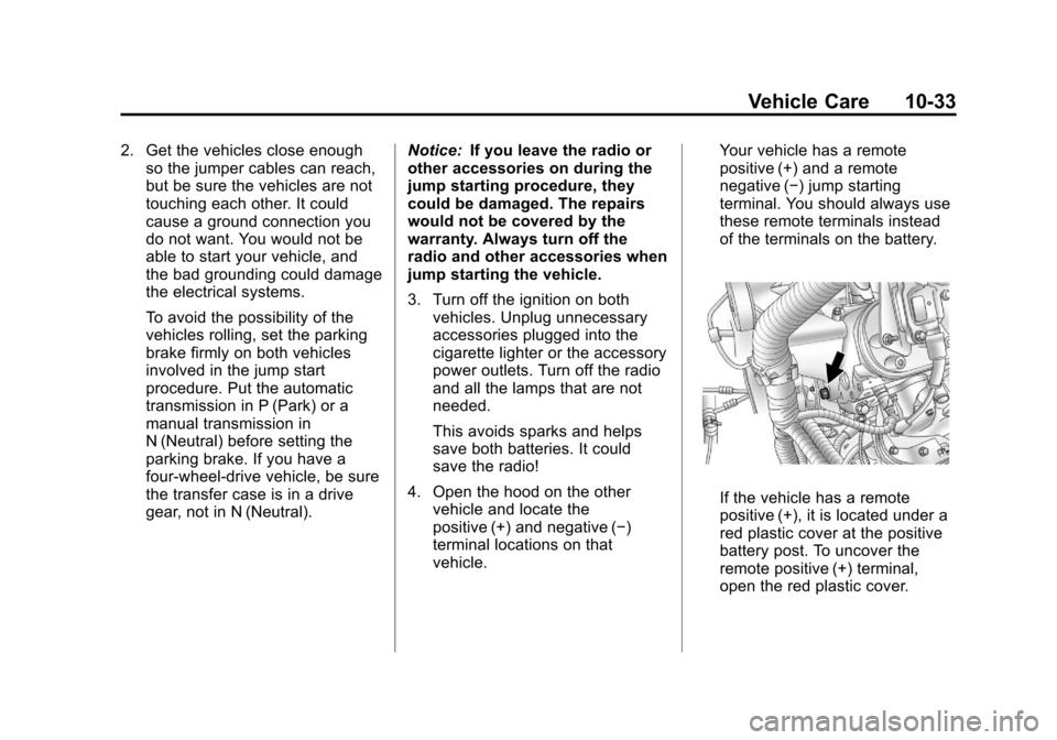
If the vehicle has a remote
positive (+), it is located under a
red plastic cover at the positive
battery post. To uncover the
remote positive (+) terminal,
open the red plastic cover.
Page 82 of 98
Black plate (34,1)Chevrolet Tahoe and GMC Yukon/Yukon Denali Hybrid - 2011
10-34 Vehicle Care
5. The remote negative (−) is asolid engine ground.
{WARNING
An electric fan can start up even
when the engine is not running
and can injure you. Keep hands,
clothing and tools away from any
underhood electric fan.
{WARNING
Using an open flame near a
battery can cause battery gas to
explode. People have been hurt
doing this, and some have been
blinded. Use a flashlight if you
need more light.
Be sure the battery has enough
water. You do not need to add
water to the battery installed in
your new vehicle. But if a battery
has filler caps, be sure the right
(Continued)
WARNING (Continued)
amount of fluid is there. If it is low,
add water to take care of that
first. If you do not, explosive gas
could be present.
Battery fluid contains acid that
can burn you. Do not get it on
you. If you accidentally get it in
your eyes or on your skin, flush
the place with water and get
medical help immediately.
{WARNING
Fans or other moving engine
parts can injure you badly. Keep
your hands away from moving
parts once the engine is running.
6. Check that the jumper cables do not have loose or missing
insulation. If they do, you could
get a shock. The vehicles could
be damaged too. Before you connect the cables,
here are some basic things you
should know. Positive (+) goes to
positive (+) or to a remote
positive (+) terminal if the vehicle
has one. Negative (−) will go to a
heavy, unpainted metal engine
part or a solid engine ground.
Do not connect positive (+) to
negative (−) or you will get a
short that would damage the
battery and maybe other parts
too. Do not connect the
negative (−) cable to the
negative (−) terminal on the dead
battery because this can cause
sparks.
7. Connect the red positive (+) cable to the positive (+) terminal
of the vehicle with the dead
battery. Use a remote
positive (+) if the vehicle
has one.
Page 95 of 98
Black plate (1,1)Chevrolet Tahoe and GMC Yukon/Yukon Denali Hybrid - 2011
INDEX i-1
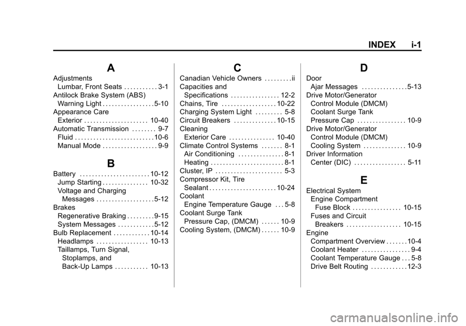
A
AdjustmentsLumbar, Front Seats . . . . . . . . . . . 3-1
Antilock Brake System (ABS) Warning Light . . . . . . . . . . . . . . . . . 5-10
Appearance Care Exterior . . . . . . . . . . . . . . . . . . . . . 10-40
Automatic Transmission . . . . . . . . 9-7 Fluid . . . . . . . . . . . . . . . . . . . . . . . . . . 10-6
Manual Mode . . . . . . . . . . . . . . . . . . 9-9
B
Battery . . . . . . . . . . . . . . . . . . . . . . . 10-12Jump Starting . . . . . . . . . . . . . . . 10-32
Voltage and ChargingMessages . . . . . . . . . . . . . . . . . . . 5-12
Brakes Regenerative Braking . . . . . . . . . 9-15
System Messages . . . . . . . . . . . . 5-12
Bulb Replacement . . . . . . . . . . . . 10-14 Headlamps . . . . . . . . . . . . . . . . . 10-13
Taillamps, Turn Signal,Stoplamps, and
Back-Up Lamps . . . . . . . . . . . 10-13
C
Canadian Vehicle Owners . . . . . . . . . ii
Capacities and
Specifications . . . . . . . . . . . . . . . . 12-2
Chains, Tire . . . . . . . . . . . . . . . . . . 10-22
Charging System Light . . . . . . . . . 5-8
Circuit Breakers . . . . . . . . . . . . . . 10-15
Cleaning Exterior Care . . . . . . . . . . . . . . . 10-40
Climate Control Systems . . . . . . . 8-1 Air Conditioning . . . . . . . . . . . . . . . 8-1
Heating . . . . . . . . . . . . . . . . . . . . . . . . 8-1
Cluster, IP . . . . . . . . . . . . . . . . . . . . . . 5-3
Compressor Kit, Tire Sealant . . . . . . . . . . . . . . . . . . . . . . 10-24
Coolant
Engine Temperature Gauge . . . 5-8
Coolant Surge Tank Pressure Cap, (DMCM) . . . . . . 10-9
Cooling System, (DMCM) . . . . . . 10-9
D
Door
Ajar Messages . . . . . . . . . . . . . . . 5-13
Drive Motor/Generator Control Module (DMCM)
Coolant Surge Tank
Pressure Cap . . . . . . . . . . . . . . . . 10-9
Drive Motor/Generator Control Module (DMCM)
Cooling System . . . . . . . . . . . . . . 10-9
Driver Information
Center (DIC) . . . . . . . . . . . . . . . . . 5-11
E
Electrical SystemEngine CompartmentFuse Block . . . . . . . . . . . . . . . . 10-15
Fuses and Circuit
Breakers . . . . . . . . . . . . . . . . . . 10-15
Engine Compartment Overview . . . . . . . 10-4
Coolant Heater . . . . . . . . . . . . . . . . 9-4
Coolant Temperature Gauge . . . 5-8
Drive Belt Routing . . . . . . . . . . . . 12-3
Page 96 of 98
Black plate (2,1)Chevrolet Tahoe and GMC Yukon/Yukon Denali Hybrid - 2011
i-2 INDEX
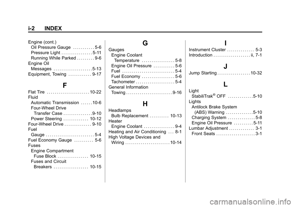
Engine (cont.)Oil Pressure Gauge . . . . . . . . . . . 5-6
Pressure Light . . . . . . . . . . . . . . . . 5-11
Running While Parked . . . . . . . . . 9-6
Engine Oil Messages . . . . . . . . . . . . . . . . . . . . 5-13
Equipment, Towing . . . . . . . . . . . . 9-17
F
Flat Tire . . . . . . . . . . . . . . . . . . . . . . 10-22
Fluid Automatic Transmission . . . . . . 10-6
Four-Wheel DriveTransfer Case . . . . . . . . . . . . . . . 9-10
Power Steering . . . . . . . . . . . . . 10-12
Four-Wheel Drive . . . . . . . . . . . . . . 9-10
Fuel
Gauge . . . . . . . . . . . . . . . . . . . . . . . . . 5-4
Fuel Economy Gauge . . . . . . . . . . 5-6
Fuses Engine CompartmentFuse Block . . . . . . . . . . . . . . . . 10-15
Fuses and Circuit Breakers . . . . . . . . . . . . . . . . . . 10-15
G
GaugesEngine CoolantTemperature . . . . . . . . . . . . . . . . . 5-8
Engine Oil Pressure . . . . . . . . . . . 5-6
Fuel . . . . . . . . . . . . . . . . . . . . . . . . . . . 5-4
Fuel Economy . . . . . . . . . . . . . . . . . 5-6
Tachometer . . . . . . . . . . . . . . . . . . . . 5-4
General Information Towing . . . . . . . . . . . . . . . . . . . . . . . . 9-16
H
HeadlampsBulb Replacement . . . . . . . . . . 10-13
Heater Engine Coolant . . . . . . . . . . . . . . . . 9-4
Heating and Air Conditioning . . . 8-1
High Voltage Devices and Wiring . . . . . . . . . . . . . . . . . . . . . . . 10-14
I
Instrument Cluster . . . . . . . . . . . . . . 5-3
Introduction . . . . . . . . . . . . . . . . . . . ii, 7-1
J
Jump Starting . . . . . . . . . . . . . . . . . 10-32
L
LightStabiliTrak®OFF . . . . . . . . . . . . . 5-10
Lights
Antilock Brake System(ABS) Warning . . . . . . . . . . . . . . 5-10
Charging System . . . . . . . . . . . . . . 5-8
Engine Oil Pressure . . . . . . . . . . 5-11
Lumbar Adjustment . . . . . . . . . . . . . 3-1 Front Seats . . . . . . . . . . . . . . . . . . . . 3-1
Page 97 of 98
Black plate (3,1)Chevrolet Tahoe and GMC Yukon/Yukon Denali Hybrid - 2011
INDEX i-3
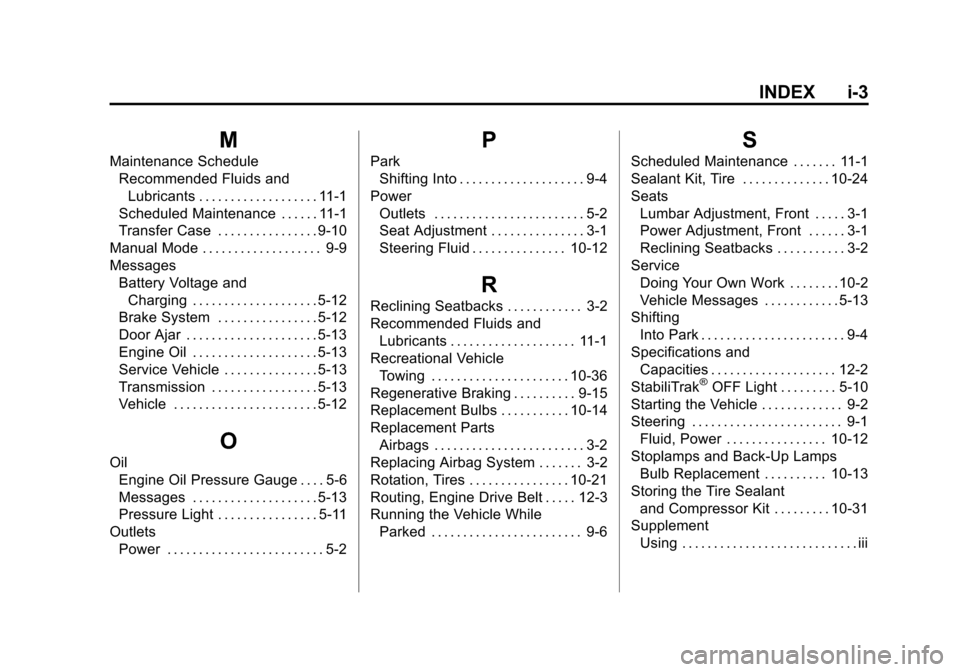
M
Maintenance ScheduleRecommended Fluids andLubricants . . . . . . . . . . . . . . . . . . . 11-1
Scheduled Maintenance . . . . . . 11-1
Transfer Case . . . . . . . . . . . . . . . . 9-10
Manual Mode . . . . . . . . . . . . . . . . . . . 9-9
Messages
Battery Voltage andCharging . . . . . . . . . . . . . . . . . . . . 5-12
Brake System . . . . . . . . . . . . . . . . 5-12
Door Ajar . . . . . . . . . . . . . . . . . . . . . 5-13
Engine Oil . . . . . . . . . . . . . . . . . . . . 5-13
Service Vehicle . . . . . . . . . . . . . . . 5-13
Transmission . . . . . . . . . . . . . . . . . 5-13
Vehicle . . . . . . . . . . . . . . . . . . . . . . . 5-12
O
Oil
Engine Oil Pressure Gauge . . . . 5-6
Messages . . . . . . . . . . . . . . . . . . . . 5-13
Pressure Light . . . . . . . . . . . . . . . . 5-11
Outlets
Power . . . . . . . . . . . . . . . . . . . . . . . . . 5-2
P
ParkShifting Into . . . . . . . . . . . . . . . . . . . . 9-4
Power Outlets . . . . . . . . . . . . . . . . . . . . . . . . 5-2
Seat Adjustment . . . . . . . . . . . . . . . 3-1
Steering Fluid . . . . . . . . . . . . . . . 10-12
R
Reclining Seatbacks . . . . . . . . . . . . 3-2
Recommended Fluids andLubricants . . . . . . . . . . . . . . . . . . . . 11-1
Recreational Vehicle
Towing . . . . . . . . . . . . . . . . . . . . . . 10-36
Regenerative Braking . . . . . . . . . . 9-15
Replacement Bulbs . . . . . . . . . . . 10-14
Replacement Parts Airbags . . . . . . . . . . . . . . . . . . . . . . . . 3-2
Replacing Airbag System . . . . . . . 3-2
Rotation, Tires . . . . . . . . . . . . . . . . 10-21
Routing, Engine Drive Belt . . . . . 12-3
Running the Vehicle While Parked . . . . . . . . . . . . . . . . . . . . . . . . 9-6
S
Scheduled Maintenance . . . . . . . 11-1
Sealant Kit, Tire . . . . . . . . . . . . . . 10-24
Seats
Lumbar Adjustment, Front . . . . . 3-1
Power Adjustment, Front . . . . . . 3-1
Reclining Seatbacks . . . . . . . . . . . 3-2
Service Doing Your Own Work . . . . . . . . 10-2
Vehicle Messages . . . . . . . . . . . . 5-13
Shifting
Into Park . . . . . . . . . . . . . . . . . . . . . . . 9-4
Specifications and Capacities . . . . . . . . . . . . . . . . . . . . 12-2
StabiliTrak
®OFF Light . . . . . . . . . 5-10
Starting the Vehicle . . . . . . . . . . . . . 9-2
Steering . . . . . . . . . . . . . . . . . . . . . . . . 9-1
Fluid, Power . . . . . . . . . . . . . . . . 10-12
Stoplamps and Back-Up Lamps Bulb Replacement . . . . . . . . . . 10-13
Storing the Tire Sealant and Compressor Kit . . . . . . . . . 10-31
Supplement Using . . . . . . . . . . . . . . . . . . . . . . . . . . . . iii