oil CHEVROLET TAHOE 2012 3.G Owners Manual
[x] Cancel search | Manufacturer: CHEVROLET, Model Year: 2012, Model line: TAHOE, Model: CHEVROLET TAHOE 2012 3.GPages: 60, PDF Size: 1.12 MB
Page 36 of 60
Black plate (6,1)Chevrolet Tahoe Police and Special Service Packages - 2012
15-6 Special Equipment Options
6. Reconnect the negative (−)battery cable to the battery.
Torque the bolt to 5 Y
(3.6 lb ft).
7. Reset the clock time and radio pushbuttons as desired.
The 12‐volt battery power is
supplied through two underhood
mega fuses, one 125 amp and one
60 amp. This underhood power is
fed to the breaker/relay center via a
harness that passes through the
driver side front of the dash, and
routes across the instrument panel
to a position forward of the glove
box. The breaker/relay center is
mounted to the instrument panel
structure forward of the glove box.
The center includes a plastic
bracket, two relays, two 30 amp
breakers and three 50 amp mega
circuit breakers. Two 30 amp breakers supply power
from the underhood 60 amp mega
fuse through the contacts of the
control relays to 3.0 mm² (12 gauge)
blunt cut wires. These two blunt cut
leads are part of wire coil under the
instrument panel near the center of
the vehicle.
Each relay is operated by a 0.5 mm²
(20 gauge) blunt cut, light or dark
blue control lead included in the
122 cm (4 ft) loop of wire coiled
under the instrument panel.
Three 50 amp mega circuit
breakers, protected by three fusible
links, supply power directly from the
underhood 125 amp mega fuse
through three, 5.0 mm² (10 gauge)
wires. Two of the wires are routed
through the body harness to buss
junction blocks in the left rear of the
cargo area and secured near the
jack and tools. This 122 cm (4 ft) of
coiled wires can be accessed by
removing the cup holder on the top
of the trim panel. The third 5 mm²
(10 gauge) wire is a blunt cut lead
which is part of the 122 cm (4 ft)
loop of wire coiled under the
instrument panel near the center of
the vehicle.
An 8 mm² (8 gauge) ground lead is
also provided, and it is located
under the front passenger sill plate.
It can be accessed by removing the
sill plate and pulling the loop of wire
at the front of the plate. The lead is
122 cm (4 ft) long.
Page 37 of 60
Black plate (7,1)Chevrolet Tahoe Police and Special Service Packages - 2012
Special Equipment Options 15-7
Blunt cut ignition controlled power
and signal circuits are also included
in the wire coiled under the
instrument panel near the center of
the vehicle. They include:
.*A yellow, 0.5 mm² (20 gauge)
circuit, Hot in ACCESSORY,
RUN or RAP (Retained
Accessory Power).
.A pink, 0.5 mm² (20 gauge)
circuit, Hot in START and RUN.
(7A maximum load)
.*A yellow/black, 0.5 mm²
(20 gauge) transmission park
signal. This circuit provides
switched power when the
transmission is in P (Park) and
the engine is running. The circuit
is at 0 volts when the
transmission is in any other
position, i.e., R (Reverse),
N (Neutral), D (Drive) or
M (Manual). Note that the circuit
is also at 12 volts with the
transmission in P (Park) and the
ignition in LOCK/OFF. To avoid
the possibility of undesired
parasitic electrical load with the
ignition in LOCK/OFF it is
suggested that the Park/Signal
circuit be isolated by routing it
through the normally open
contact of a customer furnished
ignition controlled relay.
.A dark green/white, 0.5 mm²
(20 gauge) Vehicle Speed Signal
(VSS) provides 4,000 pulses
per mile.*These two circuits share a 15 amp
fuse. (10 amp combined
maximum load)
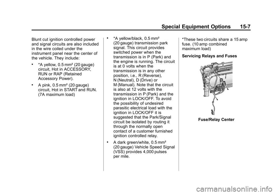
Servicing Relays and Fuses
Fuse/Relay Center
Page 39 of 60
Black plate (9,1)Chevrolet Tahoe Police and Special Service Packages - 2012
Special Equipment Options 15-9
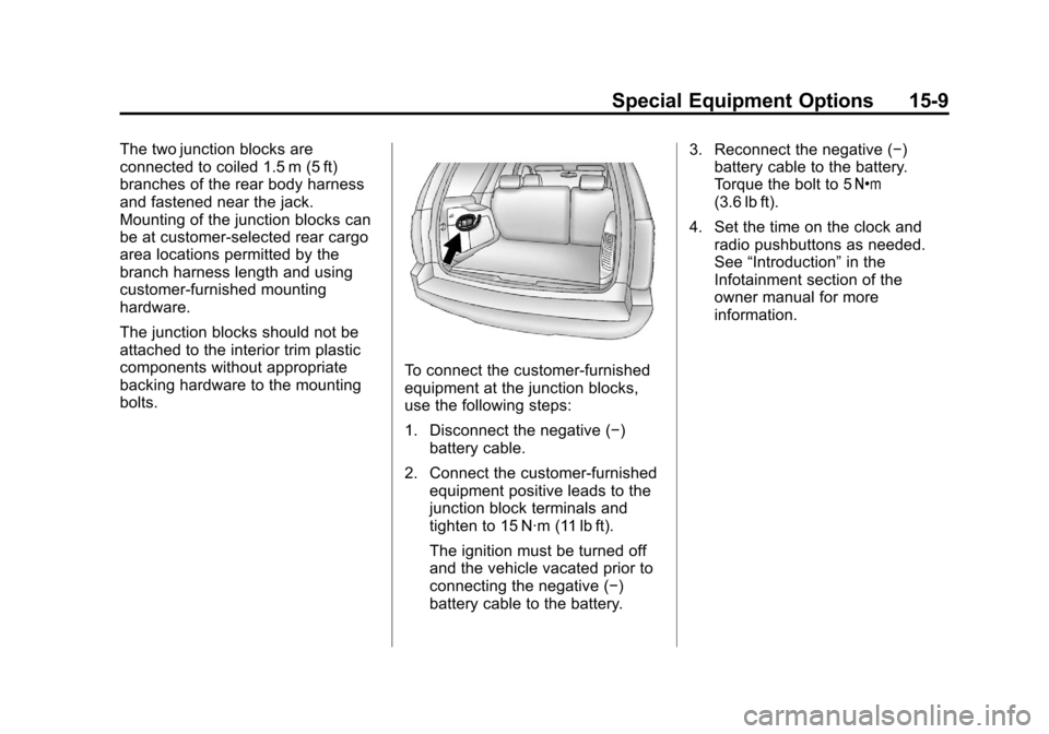
The two junction blocks are
connected to coiled 1.5 m (5 ft)
branches of the rear body harness
and fastened near the jack.
Mounting of the junction blocks can
be at customer‐selected rear cargo
area locations permitted by the
branch harness length and using
customer‐furnished mounting
hardware.
The junction blocks should not be
attached to the interior trim plastic
components without appropriate
backing hardware to the mounting
bolts.
To connect the customer-furnished
equipment at the junction blocks,
use the following steps:
1. Disconnect the negative (−)battery cable.
2. Connect the customer-furnished equipment positive leads to the
junction block terminals and
tighten to 15 N·m (11 lb ft).
The ignition must be turned off
and the vehicle vacated prior to
connecting the negative (−)
battery cable to the battery. 3. Reconnect the negative (−)
battery cable to the battery.
Torque the bolt to 5 Y
(3.6 lb ft).
4. Set the time on the clock and radio pushbuttons as needed.
See “Introduction” in the
Infotainment section of the
owner manual for more
information.
Page 40 of 60
Black plate (10,1)Chevrolet Tahoe Police and Special Service Packages - 2012
15-10 Special Equipment Options
Equipment Grounding
Studs - Rear
Compartment
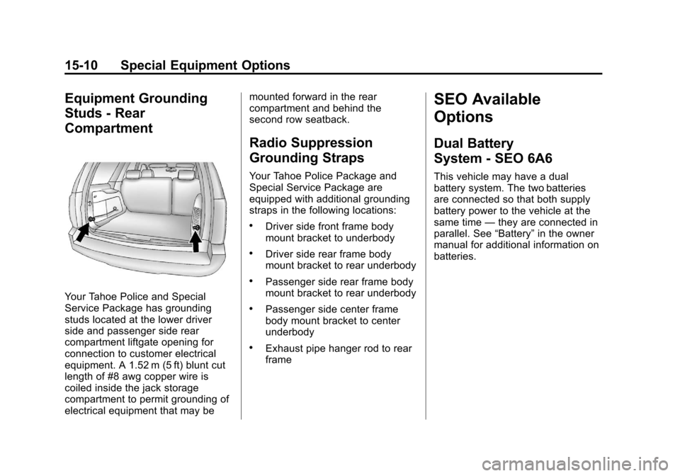
Your Tahoe Police and Special
Service Package has grounding
studs located at the lower driver
side and passenger side rear
compartment liftgate opening for
connection to customer electrical
equipment. A 1.52 m (5 ft) blunt cut
length of #8 awg copper wire is
coiled inside the jack storage
compartment to permit grounding of
electrical equipment that may bemounted forward in the rear
compartment and behind the
second row seatback.
Radio Suppression
Grounding Straps
Your Tahoe Police Package and
Special Service Package are
equipped with additional grounding
straps in the following locations:
.Driver side front frame body
mount bracket to underbody
.Driver side rear frame body
mount bracket to rear underbody
.Passenger side rear frame body
mount bracket to rear underbody
.Passenger side center frame
body mount bracket to center
underbody
.Exhaust pipe hanger rod to rear
frame
SEO Available
Options
Dual Battery
System - SEO 6A6
This vehicle may have a dual
battery system. The two batteries
are connected so that both supply
battery power to the vehicle at the
same time
—they are connected in
parallel. See “Battery”in the owner
manual for additional information on
batteries.
Page 41 of 60
Black plate (11,1)Chevrolet Tahoe Police and Special Service Packages - 2012
Special Equipment Options 15-11
Exterior Lamp
Emergency Flashing
System - SEO 6J7
SEO 6J7 provides a high-beam
headlamps flashing module, rear
lamps flashing and control wire for a
customer-furnished switch to turn
the module on or off. The flasher
control wire is coiled under the
center of the instrument panel. This
control lead may be combined with
the interior wiring leads for SEO 6J3
when that option is ordered with
SEO 6J7.The headlamps flashing module is
located below the passenger side
front headlamp and forward of the
passenger side front wheel. The
module is connected to an inline
connector in the forward lamp
harness. The headlamps flashing
module is activated by the
application of 12 volts to a dark
green/red wire coiled in the
passenger side footwell. When
activated, the driver and passenger
side high-beam headlamps and the
high-beam instrument panel cluster
light will flash alternately at
2.4 flashes per second.
When the headlamps flashing
module is turned on, the module
sends a signal to the Body Control
Module (BCM). The BCM alternately
flashes the stop lamps and backup
lamps. Depressing the brake pedal
will override the stop lamp flashing
and placing the transmission in
reverse will override the backup
lamp flashing.Activation of the headlamp and
rearlamp flashing can be separated.
Call Kerr Industries at 905‐725‐6561
During daylight conditions, the
Daytime Running Lamps (DRL) are
automatically turned off whenever
the headlamps flasher module is
activated. During nighttime
conditions, the low-beam
headlamps turn on automatically
while the high-beam headlamps
flash. Turning on the high-beam
headlamps manually with the turn
signal/multifunction lever will
override the flashing module and
the high-beam headlamps will
operate continuously.
Page 46 of 60
Black plate (16,1)Chevrolet Tahoe Police and Special Service Packages - 2012
15-16 Special Equipment Options
3. The accessory harness is coiltied to the passenger side of the
vehicle at the console inner
bracket.
4. Cut the tape holding the harness coil.
5. As one person watches the roof hole from the outside for the end
of the harness, a second person
from the inside of the vehicle
should snake the harness
toward the hole.
6. Pull out the wiring harness being careful to avoid scraping the
insulation on the edge of
the hole.
7. Extend the wiring harness to the accessory. 8. Connect the dark green wire to
the accessory hot terminal.
9. Connect the black wire to the accessory ground terminal.
10. Cover the hole in the roof with a durable sealant such as
silicone rubber sealer.
11. Reinstall the overhead console access panel/lamp lenses.
Option B: Use Wiring Harness
Package 12150250. Obtain from
GM Service Parts through the GM
Dealership
1. Drill a 32 mm (1.25 in) hole in the outer roof panel in the area
shown in the illustration. The
hole should only go through the
outer panel. Remove all sharp
edges from the drilled hole.
2. Remove the inside overhead console access panel/lamp
lenses. 3. The accessory harness is coil
tied to the passenger side of the
vehicle at the console inner
bracket.
4. Cut the tape holding the harness coil.
5. As one person watches the roof hole from the outside for the end
of the harness, a second person
from the inside of the vehicle
should snake the harness
toward the hole.
6. Pull out the wiring harness being careful to avoid scraping the
insulation on the edge of
the hole.
7. Cut the wire to length. Install terminals to wire ends and insert
into the connector. The dark
green wire goes to cavity A and
the black wire in cavity B. Push
in the secondary lock to retain
the wires.
Page 50 of 60
Black plate (20,1)Chevrolet Tahoe Police and Special Service Packages - 2012
15-20 Special Equipment Options
Maintenance
The emergency roof light circuit is
fed from the fuse labeled Sunroof
located in the underhood electrical
center. Always replace the fuse with
a 30 amp mini-fuse.
Wiring Provisions
for Horn/Siren
Circuit - SEO 6J4
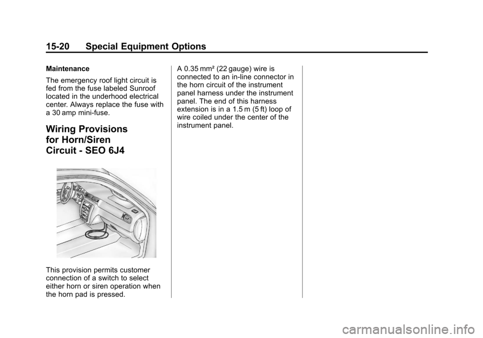
This provision permits customer
connection of a switch to select
either horn or siren operation when
the horn pad is pressed.A 0.35 mm² (22 gauge) wire is
connected to an in-line connector in
the horn circuit of the instrument
panel harness under the instrument
panel. The end of this harness
extension is in a 1.5 m (5 ft) loop of
wire coiled under the center of the
instrument panel.
Page 52 of 60
Black plate (22,1)Chevrolet Tahoe Police and Special Service Packages - 2012
15-22 Special Equipment Options
Wiring Provisions for
Vehicle Grille Lamps,
Flasher, and Speaker/
Siren - SEO 6J3
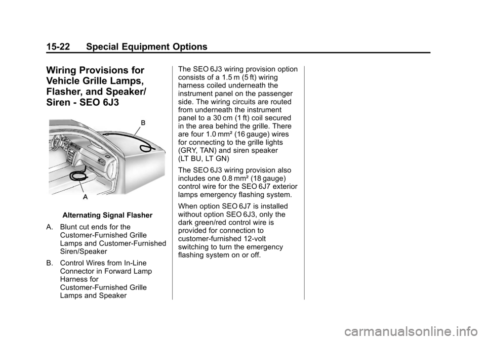
Alternating Signal Flasher
A. Blunt cut ends for the Customer-Furnished Grille
Lamps and Customer-Furnished
Siren/Speaker
B. Control Wires from In-Line Connector in Forward Lamp
Harness for
Customer-Furnished Grille
Lamps and Speaker The SEO 6J3 wiring provision option
consists of a 1.5 m (5 ft) wiring
harness coiled underneath the
instrument panel on the passenger
side. The wiring circuits are routed
from underneath the instrument
panel to a 30 cm (1 ft) coil secured
in the area behind the grille. There
are four 1.0 mm² (16 gauge) wires
for connecting to the grille lights
(GRY, TAN) and siren speaker
(LT BU, LT GN)
The SEO 6J3 wiring provision also
includes one 0.8 mm² (18 gauge)
control wire for the SEO 6J7 exterior
lamps emergency flashing system.
When option SEO 6J7 is installed
without option SEO 6J3, only the
dark green/red control wire is
provided for connection to
customer-furnished 12-volt
switching to turn the emergency
flashing system on or off.
Page 54 of 60
Black plate (24,1)Chevrolet Tahoe Police and Special Service Packages - 2012
15-24 Special Equipment Options
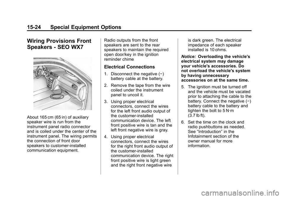
Wiring Provisions Front
Speakers - SEO WX7
About 165 cm (65 in) of auxiliary
speaker wire is run from the
instrument panel radio connector
and is coiled under the center of the
instrument panel. The wiring permits
the connection of front door
speakers to customer-installed
communication equipment.Radio outputs from the front
speakers are sent to the rear
speakers to maintain the required
open door/key in the ignition
reminder chime
Electrical Connections
1. Disconnect the negative (−)
battery cable at the battery.
2. Remove the tape from the wire coiled under the instrument
panel to uncoil it.
3. Using proper electrical connectors, connect the wires
for the left front audio output of
the customer-installed
communication device. The left
front positive wire is tan and the
left front negative wire is gray.
4. Using proper electrical connectors, connect the wires
for the right front audio output of
the customer-installed
communication device. The right
front positive wire is light green
and the right front negative wire is dark green. The electrical
impedance of each speaker
installed is 10 ohms.
Notice: Overloading the vehicle's
electrical system may damage
your vehicle's accessories. Do
not overload the vehicle's system
by having unnecessary
accessories on at the same time.
5. The ignition must be turned off and the vehicle must be vacated
prior to attaching the cable to the
battery. Connect the negative (−)
battery cable to the battery and
tighten the bolt to 5 N·m
(3.7 lb ft).
6. Set the time on the clock and radio pushbuttons as needed.
See “Introduction” in the
Infotainment section of the
owner manual for more
information.