CHEVROLET UPLANDER 2009 1.G Owners Manual
Manufacturer: CHEVROLET, Model Year: 2009, Model line: UPLANDER, Model: CHEVROLET UPLANDER 2009 1.GPages: 464, PDF Size: 2.59 MB
Page 351 of 464

To disconnect the jumper cables from both vehicles, do
the following:
1. Disconnect the black negative (−) cable from the
vehicle that had the dead battery.
2. Disconnect the black negative (−) cable from the
vehicle with the good battery.
3. Disconnect the red positive (+) cable from the
vehicle with the good battery.
4. Disconnect the red positive (+) cable from the other
vehicle.
5. Return the remote positive (+) terminal cover or
underhood fuse block cover to its original position.
Headlamp Aiming
Headlamp aim has been preset at the factory and
should need no further adjustment.
However, if your vehicle is damaged in a crash, the
headlamp aim may be affected. Aim adjustment to the
low-beam headlamps may be necessary if oncoming
drivers �ash their high-beam headlamps at you
(for vertical aim).
If the headlamps need to be re-aimed, it is
recommended that you take the vehicle to your
dealer/retailer for service.
Bulb Replacement
For the proper type of replacement bulbs, see
Replacement Bulbs on page 5-45.
For any bulb changing procedure not listed in this
section, contact your dealer/retailer.
Halogen Bulbs
{CAUTION:
Halogen bulbs have pressurized gas inside and
can burst if you drop or scratch the bulb. You or
others could be injured. Be sure to read and follow
the instructions on the bulb package.
5-41
Page 352 of 464
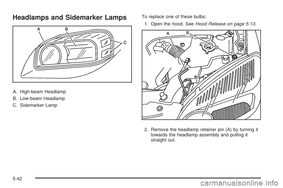
Headlamps and Sidemarker Lamps
A. High-beam Headlamp
B. Low-beam Headlamp
C. Sidemarker LampTo replace one of these bulbs:
1. Open the hood. SeeHood Release on page 5-13.
2. Remove the headlamp retainer pin (A) by turning it
towards the headlamp assembly and pulling it
straight out.
5-42
Page 353 of 464
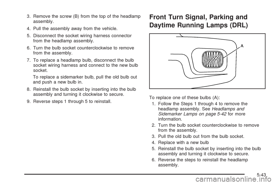
3. Remove the screw (B) from the top of the headlamp
assembly.
4. Pull the assembly away from the vehicle.
5. Disconnect the socket wiring harness connector
from the headlamp assembly.
6. Turn the bulb socket counterclockwise to remove
from the assembly.
7. To replace a headlamp bulb, disconnect the bulb
socket wiring harness and connect to the new bulb
socket.
To replace a sidemarker bulb, pull the old bulb out
and push a new bulb in.
8. Reinstall the bulb socket by inserting into the bulb
assembly and turning it clockwise to secure.
9. Reverse steps 1 through 5 to reinstall.Front Turn Signal, Parking and
Daytime Running Lamps (DRL)
To replace one of these bulbs (A):
1. Follow the Steps 1 through 4 to remove the
headlamp assembly. SeeHeadlamps and
Sidemarker Lamps on page 5-42for more
information.
2. Turn the bulb socket counterclockwise to remove
from the assembly.
3. Pull the old bulb out from the bulb socket.
4. Replace with a new bulb
5. Reinstall the bulb socket by inserting into the bulb
assembly and turning it clockwise to secure.
6. Reverse the steps to reinstall the headlamp
assembly.
5-43
Page 354 of 464
Taillamps, Turn Signal, Stoplamps
and Back-up Lamps
To change a stoplamp/taillamp, turn signal or back-up
lamp bulb:
1. Open the liftgate. SeeLiftgate on page 2-22for
more information.
2. Remove the two screws
from the taillamp
housing on the
inboard side.
3. Pull out the taillamp housing.
4. Disconnect the wiring harness connector from the
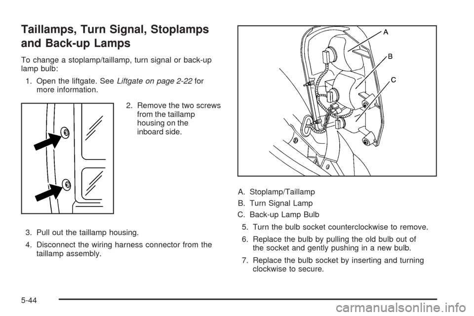
taillamp assembly.A. Stoplamp/Taillamp
B. Turn Signal Lamp
C. Back-up Lamp Bulb
5. Turn the bulb socket counterclockwise to remove.
6. Replace the bulb by pulling the old bulb out of
the socket and gently pushing in a new bulb.
7. Replace the bulb socket by inserting and turning
clockwise to secure.
5-44
Page 355 of 464
8. Reinstall the taillamp assembly by inserting the
outboard locating/retaining pins until the lamp is
seated.
9. Secure with the inboard screws.
License Plate Lamp
To replace one of these bulbs:
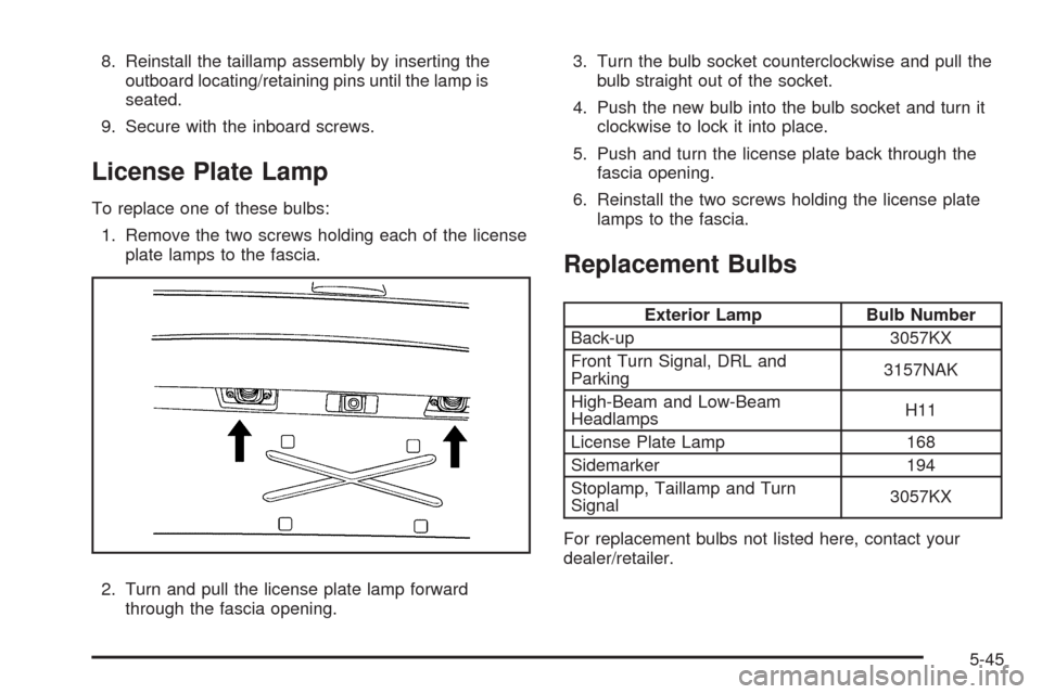
1. Remove the two screws holding each of the license
plate lamps to the fascia.
2. Turn and pull the license plate lamp forward
through the fascia opening.3. Turn the bulb socket counterclockwise and pull the
bulb straight out of the socket.
4. Push the new bulb into the bulb socket and turn it
clockwise to lock it into place.
5. Push and turn the license plate back through the
fascia opening.
6. Reinstall the two screws holding the license plate
lamps to the fascia.
Replacement Bulbs
Exterior Lamp Bulb Number
Back-up 3057KX
Front Turn Signal, DRL and
Parking3157NAK
High-Beam and Low-Beam
HeadlampsH11
License Plate Lamp 168
Sidemarker 194
Stoplamp, Taillamp and Turn
Signal3057KX
For replacement bulbs not listed here, contact your
dealer/retailer.
5-45
Page 356 of 464
Windshield Wiper Blade
Replacement
Windshield wiper blades should be inspected for wear
and cracking. SeeScheduled Maintenance on page 6-4
for more information.
Replacement blades come in different types and are
removed in different ways. For proper type and length,
seeMaintenance Replacement Parts on page 6-13.
To replace the windshield wiper blade assembly do the
following:
1. Lift the wiper arm and turn the blade until it is
facing away from the windshield.
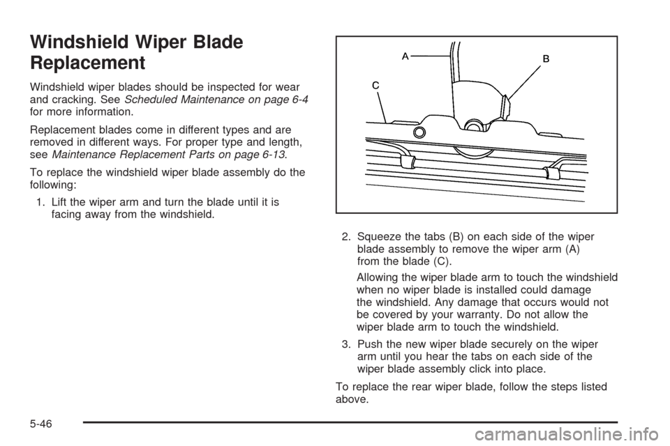
2. Squeeze the tabs (B) on each side of the wiper
blade assembly to remove the wiper arm (A)
from the blade (C).
Allowing the wiper blade arm to touch the windshield
when no wiper blade is installed could damage
the windshield. Any damage that occurs would not
be covered by your warranty. Do not allow the
wiper blade arm to touch the windshield.
3. Push the new wiper blade securely on the wiper
arm until you hear the tabs on each side of the
wiper blade assembly click into place.
To replace the rear wiper blade, follow the steps listed
above.
5-46
Page 357 of 464

Tires
Your new vehicle comes with high-quality tires
made by a leading tire manufacturer. If you ever
have questions about your tire warranty and where
to obtain service, see your vehicle Warranty
booklet for details.
{CAUTION:
Poorly maintained and improperly used
tires are dangerous.
Overloading your tires can cause
overheating as a result of too much
�exing. You could have an air-out and
a serious accident. SeeLoading the
Vehicle on page 4-19.
CAUTION: (Continued)
CAUTION: (Continued)
Underin�ated tires pose the same danger
as overloaded tires. The resulting accident
could cause serious injury. Check all tires
frequently to maintain the recommended
pressure. Tire pressure should be
checked when your tires are cold. See
Inflation - Tire Pressure on page 5-54.
Overin�ated tires are more likely to be
cut, punctured, or broken by a sudden
impact — such as when you hit a pothole.
Keep tires at the recommended pressure.
Worn, old tires can cause accidents.
If your tread is badly worn, or if your tires
have been damaged, replace them.
SeeHigh-Speed Operation on page 5-56for
in�ation pressure adjustment for high speed
driving.
5-47
Page 358 of 464
Tire Sidewall Labeling
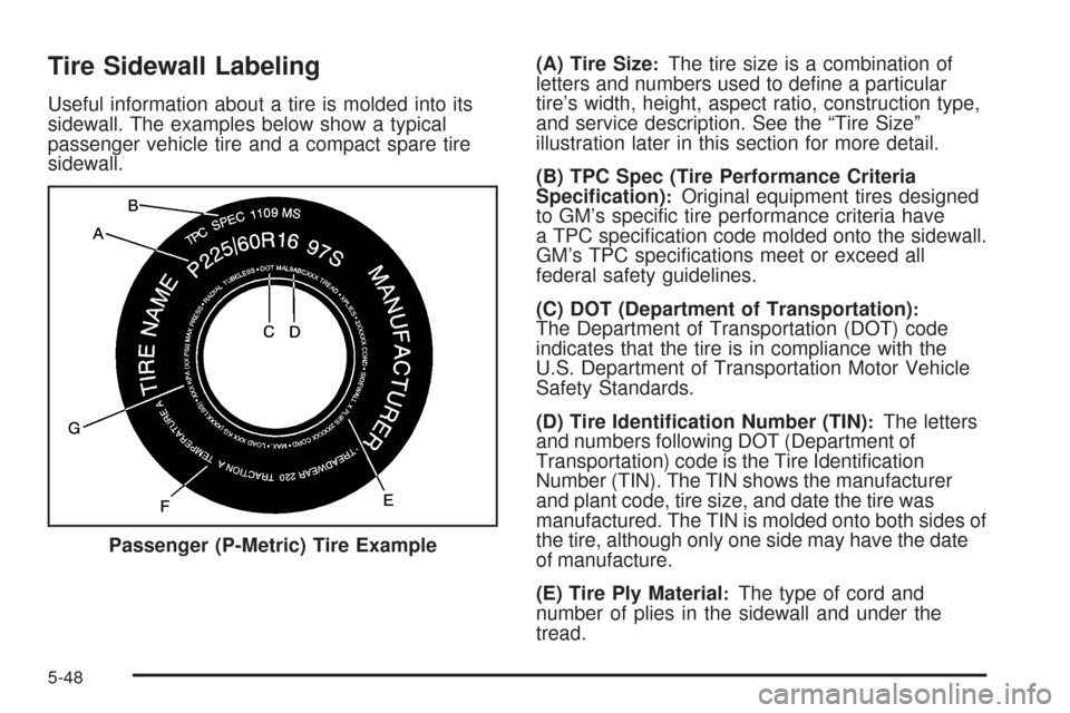
Useful information about a tire is molded into its
sidewall. The examples below show a typical
passenger vehicle tire and a compact spare tire
sidewall.(A) Tire Size
:The tire size is a combination of
letters and numbers used to de�ne a particular
tire’s width, height, aspect ratio, construction type,
and service description. See the “Tire Size”
illustration later in this section for more detail.
(B) TPC Spec (Tire Performance Criteria
Speci�cation)
:Original equipment tires designed
to GM’s speci�c tire performance criteria have
a TPC speci�cation code molded onto the sidewall.
GM’s TPC speci�cations meet or exceed all
federal safety guidelines.
(C) DOT (Department of Transportation)
:The Department of Transportation (DOT) code
indicates that the tire is in compliance with the
U.S. Department of Transportation Motor Vehicle
Safety Standards.
(D) Tire Identi�cation Number (TIN)
:The letters
and numbers following DOT (Department of
Transportation) code is the Tire Identi�cation
Number (TIN). The TIN shows the manufacturer
and plant code, tire size, and date the tire was
manufactured. The TIN is molded onto both sides of
the tire, although only one side may have the date
of manufacture.
(E) Tire Ply Material
:The type of cord and
number of plies in the sidewall and under the
tread. Passenger (P-Metric) Tire Example
5-48
Page 359 of 464
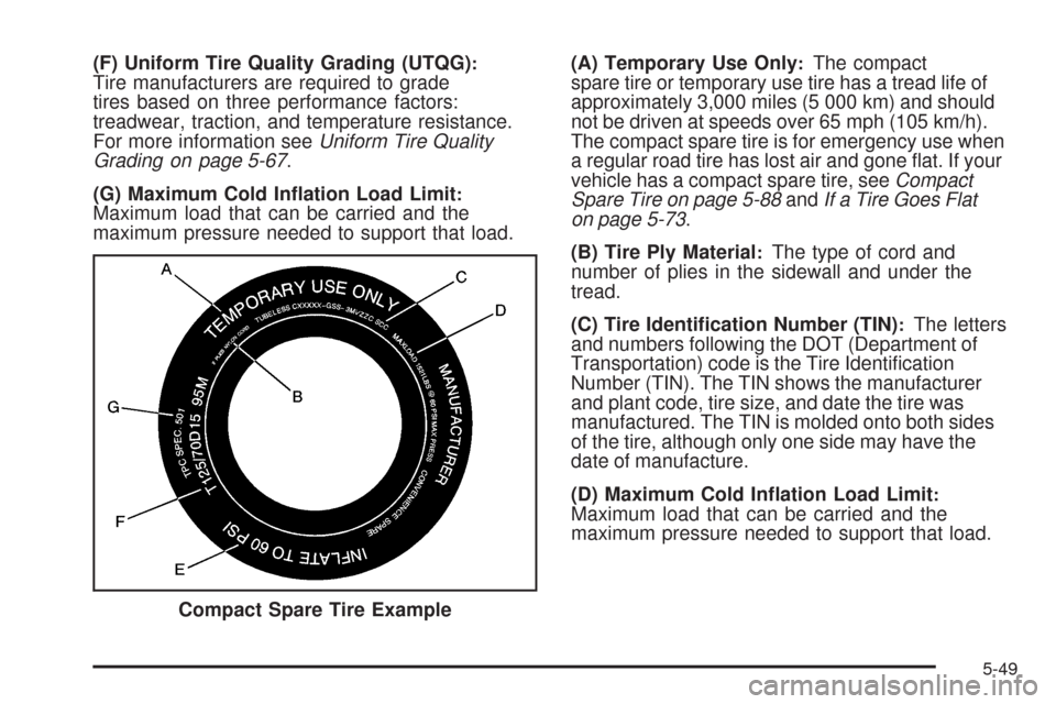
(F) Uniform Tire Quality Grading (UTQG):Tire manufacturers are required to grade
tires based on three performance factors:
treadwear, traction, and temperature resistance.
For more information seeUniform Tire Quality
Grading on page 5-67.
(G) Maximum Cold In�ation Load Limit
:Maximum load that can be carried and the
maximum pressure needed to support that load.(A) Temporary Use Only
:The compact
spare tire or temporary use tire has a tread life of
approximately 3,000 miles (5 000 km) and should
not be driven at speeds over 65 mph (105 km/h).
The compact spare tire is for emergency use when
a regular road tire has lost air and gone �at. If your
vehicle has a compact spare tire, seeCompact
Spare Tire on page 5-88andIf a Tire Goes Flat
on page 5-73.
(B) Tire Ply Material
:The type of cord and
number of plies in the sidewall and under the
tread.
(C) Tire Identi�cation Number (TIN)
:The letters
and numbers following the DOT (Department of
Transportation) code is the Tire Identi�cation
Number (TIN). The TIN shows the manufacturer
and plant code, tire size, and date the tire was
manufactured. The TIN is molded onto both sides
of the tire, although only one side may have the
date of manufacture.
(D) Maximum Cold In�ation Load Limit
:Maximum load that can be carried and the
maximum pressure needed to support that load.
Compact Spare Tire Example
5-49
Page 360 of 464
(E) Tire In�ation:The temporary use tire or
compact spare tire should be in�ated to 60 psi
(420 kPa). For more information on tire pressure
and in�ation seeInflation - Tire Pressure on
page 5-54.
(F) Tire Size
:A combination of letters and
numbers de�ne a tire’s width, height, aspect
ratio, construction type, and service description.
The letter T as the �rst character in the tire
size means the tire is for temporary use only.
(G) TPC Spec (Tire Performance Criteria
Speci�cation)
:Original equipment tires designed
to GM’s speci�c tire performance criteria have
a TPC speci�cation code molded onto the sidewall.
GM’s TPC speci�cations meet or exceed all
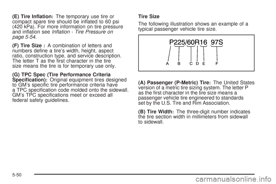
federal safety guidelines.Tire Size
The following illustration shows an example of a
typical passenger vehicle tire size.
(A) Passenger (P-Metric) Tire:The United States
version of a metric tire sizing system. The letter P
as the �rst character in the tire size means a
passenger vehicle tire engineered to standards
set by the U.S. Tire and Rim Association.
(B) Tire Width
:The three-digit number indicates
the tire section width in millimeters from sidewall
to sidewall.
5-50