Light CHRYSLER 200 2015 2.G Owner's Manual
[x] Cancel search | Manufacturer: CHRYSLER, Model Year: 2015, Model line: 200, Model: CHRYSLER 200 2015 2.GPages: 220, PDF Size: 3.7 MB
Page 24 of 220
Lighter Weight Passengers (Including Small Adults)
When a lighter weight passenger, including a small adult, occupies the front passenger seat, the
OCS may reduce the inflation rate of the Passenger Advanced Front Air Bag. This does not
mean that the OCS is working improperly.
Do not decrease OR increase the front passenger’s seated weight on the front passenger
seat
The front passenger’s seated weight must be properly positioned on the front passenger seat.
Failure to do so may result in serious injury or death. The OCS determines the most probable
classification of the occupant that it detects. The OCS will detect the front passenger’s de-
creased or increased seated weight, which may result in an adjusted inflation rate of the
Passenger Advanced Front Air Bag in a collision. This does not mean that the OCS is working
improperly. Decreasing the front passenger’s seated weight on the front passenger seat may
result in a reduced-power deployment of the Passenger Advanced Front Air Bag. Increasing the
front passenger’s seated weight on the front passenger seat may result in a full-power deploy-
ment of the Passenger Advanced Front Air Bag. Examples of improper front passenger seating
include:
• The front passenger’s weight is transferred to another part of the vehicle (like the door, armrest or instrument panel).
• The front passenger leans forward, sideways, or turns to face the rear of the vehicle.
• The front passenger’s seatback is not in the full upright position.
• The front passenger carries or holds an object while seated (e.g., backpack, box, etc.).
• Objects are lodged under the front passenger seat.
• Objects are lodged between the front passenger seat and center console.
• Accessories that may change the seated weight on the front passenger seat are attached to the front passenger seat.
• Anything that may decrease or increase the front passenger’s seated weight.
GETTING STARTED
22
Page 25 of 220
The OCS determines the front passenger’s most probable classification. If an occupant in the
front passenger seat is seated improperly, the occupant may provide an output signal to the OCS
that is different from the occupant’s properly seated weight input, for example:
The Air Bag Warning Light
will turn on
whenever the OCS is unable to classify the
front passenger seat status. A malfunction in
the OCS may affect the operation of the air
bag system.
If the Air Bag Warning Light
does not
come on, or stays on after you start the vehicle,
or it comes on as you drive, take the vehicle to
an authorized dealer for service immediately.
The passenger seat assembly contains critical
components that may affect the Passenger
Advanced Front Air Bag inflation. In order for
the OCS to properly classify the seated weight
of a front seat passenger, the OCS compo-
nents must function as designed.
Do not make any modifications to the front
passenger seat components, assembly, or to
the seat cover. If the seat, trim cover, or cushion
needs service for any reason, take the vehicle to
your authorized dealer. Only Chrysler Group
LLC approved seat accessories may be used.
The following requirements must be strictly
followed:
• Do not modify the front passenger seat as- sembly or components in any way.
• Do not use prior or future model year seat covers or cushions not designated by
Chrysler Group LLC for the specific model
being repaired. Always use the correct seat
cover and cushion specified for the vehicle.
• Do not replace the seat cover or cushion with an aftermarket seat cover or cushion.
• Do not add a secondary seat cover or mat.
• At no time should any Supplemental Re- straint System (SRS) component or SRS re-
lated component or fastener be modified or
replaced with any part except those which are approved by Chrysler Group LLC.
Not Seated Properly
Not Seated Properly
Not Seated Properly
Not Seated Properly
GETTING STARTED
23
Page 37 of 220
ENGINE BREAK-IN RECOMMENDATIONS
A long break-in period is not required for the engine and drivetrain (transmission and axle) in your
vehicle.
Drive moderately during the first 300 miles (500 km). After the initial 60 miles (100 km), speeds
up to 50 or 55 mph (80 or 90 km/h) are desirable.
While cruising, brief full-throttle acceleration within the limits of local traffic laws contributes to a
good break-in. Wide-open throttle acceleration in low gear can be detrimental and should be
avoided.
The engine oil installed in the engine at the factory is a high-quality energy conserving type
lubricant. Oil changes should be consistent with anticipated climate conditions under which
vehicle operations will occur. For the recommended viscosity and quality grades, refer to
“Maintaining Your Vehicle.”
NOTE:
A new engine may consume some oil during its first few thousand miles (kilometers) of opera-
tion. This should be considered a normal part of the break-in and not interpreted as an indica-
tion of an engine problem or malfunction.
CAUTION!
Never use Non-Detergent Oil or Straight Mineral Oil in the engine or damage may result.
TURN SIGNAL/HIGH BEAM LEVER
Turn Signals/Lane Change Assist
Tap the lever up or down once and the turn
signal (right or left) will flash three times and
automatically turn off.
Flash To Pass
• Pull the lever toward you to activate the highbeams. The high beams will remain on until
the lever is released.
High Beam Operation
• Push the lever forward to activate the highbeams.
NOTE:
For safe driving, turn off the high beams when
oncoming traffic is present to prevent head-
light glare and as a courtesy to other motorists.
Turn Signal/High Beam Lever
1 — High Beam (Push Forward)
2 — Flash To Pass (Pull Toward Driver)
OPERATING YOUR VEHICLE
35
Page 38 of 220
HEADLIGHT SWITCH
Automatic Headlights/Parking
Lights/Headlights
The headlight switch is located on the instru-
ment panel to the left of the steering wheel.
• Rotate the headlight switch to the first de-tent
for parking lights and to the
second detent
for headlights.
• With the parking lights or low beam head- lights on, push in the center of the headlight
switch once for fog lights.
• Rotate the headlight switch to the third de- tent AUTO for automatic headlights.
When set to AUTO, the system automatically
turns the headlights on or off based on ambient
light levels.
Automatic High Beams
The Automatic High Beams system provides increased forward lighting at night by automating
high beam control through the use of a digital camera mounted on the inside rearview mirror.
This camera detects vehicle specific light and automatically switches from high beams to low
beams until the approaching vehicle is out of view. This feature is programmable through the
Uconnect® system. Refer to “Uconnect® Settings” in “Understanding Your Instrument Panel” in
the Owner's Manual on the DVD for further details.
Instrument Panel Dimmer
• Rotate the right dimmer control to the extreme bottom position to fully dim the instrument panel lights and prevent the interior lights from illuminating when a door is opened.
• Rotate the right dimmer control up to increase the brightness of the instrument panel when the parking lights or headlights are on.
• Rotate the right dimmer control up to the next detent position to fully brighten the odometer and radio when the parking lights or headlights are on.
• Rotate the right dimmer control up to the last detent position to turn on the interior lighting.
• If your vehicle is equipped with a touchscreen, the dimming is programmable through the Uconnect® system. Refer to “Uconnect® Settings ” in “Understanding Your Instrument Panel”
in the Owner's Manual on the DVD for further details.
Ambient Light Dimmer
• Rotate the left dimmer control upward or downward to increase or decrease the brightness ofthe ambient light located in the overhead console, door handle lights, under I/P lights, door
map pocket lights, and cubby bin lights.
• Rotate the left dimmer control to the extreme bottom position to turn off the ambient lights.
Headlight Switch
1 — Rotate Headlight
2 — Push Fog
3 — Rotate Dimmer
OPERATING YOUR VEHICLE
36
Page 52 of 220
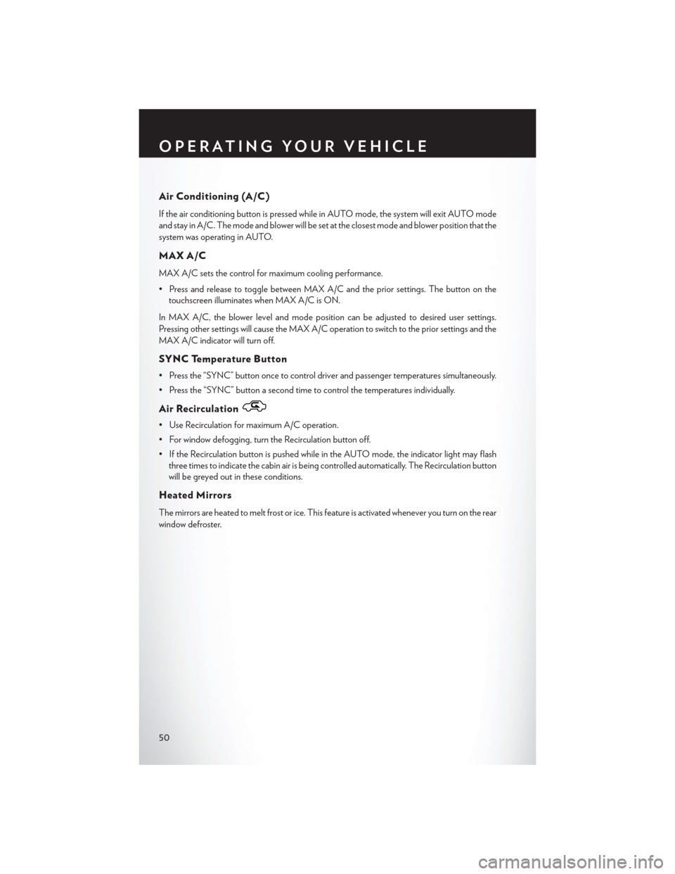
Air Conditioning (A/C)
If the air conditioning button is pressed while in AUTO mode, the system will exit AUTO mode
and stay in A/C. The mode and blower will be set at the closest mode and blower position that the
system was operating in AUTO.
MAX A/C
MAX A/C sets the control for maximum cooling performance.
• Press and release to toggle between MAX A/C and the prior settings. The button on thetouchscreen illuminates when MAX A/C is ON.
In MAX A/C, the blower level and mode position can be adjusted to desired user settings.
Pressing other settings will cause the MAX A/C operation to switch to the prior settings and the
MAX A/C indicator will turn off.
SYNC Temperature Button
• Press the “SYNC” button once to control driver and passenger temperatures simultaneously.
• Press the “SYNC” button a second time to control the temperatures individually.
Air Recirculation
• Use Recirculation for maximum A/C operation.
• For window defogging, turn the Recirculation button off.
• If the Recirculation button is pushed while in the AUTO mode, the indicator light may flash three times to indicate the cabin air is being controlled automatically. The Recirculation button
will be greyed out in these conditions.
Heated Mirrors
The mirrors are heated to melt frost or ice. This feature is activated whenever you turn on the rear
window defroster.
OPERATING YOUR VEHICLE
50
Page 56 of 220
STOP/START SYSTEM — 2.4L ENGINE
The Stop/Start function is developed to save fuel and reduce emissions. The system will stop the
engine automatically during a vehicle stop if the required conditions are met. Releasing the brake
pedal or pressing the accelerator pedal on an automatic transmission will start the engine.
Automatic Mode
The Stop/Start feature is enabled after every normal customer engine start. It will remain in
STOP/START NOT READY until you drive forward with a vehicle speed greater than 5 mph
(8 km/h). At that time, the system will go into STOP/START READY and if all other conditions
are met, can go into a STOP/START AUTOSTOP ACTIVE “Autostop” mode.
To Activate The Autostop Mode, The Following Must Occur:
• The system must be in STOP/START READY state. A STOP/START READY message willbe displayed in the Electronic Vehicle Information Center (EVIC) or Driver Information
Display (DID) within the Stop/Start section. Refer to “Electronic Vehicle Information Center
(EVIC)” or “Driver Information Display (DID)” in “Understanding Your Instrument Panel” in
your owners manual on the DVD for further information.
• The vehicle must be completely stopped.
• The shifter must be in DRIVE or NEUTRAL and the brake pedal depressed.
The engine will shut down, the tachometer will move to the zero position and the Stop/Start
telltale will illuminate indicating you are in Autostop. While in Autostop, the Climate Controls
system may automatically adjust airflow to maintain cabin comfort. Customer settings will be
maintained upon return to an engine running condition.
Refer to the “Stop/Start System” in the “Starting and Operating” section located in your owners
manual on the DVD for further information.
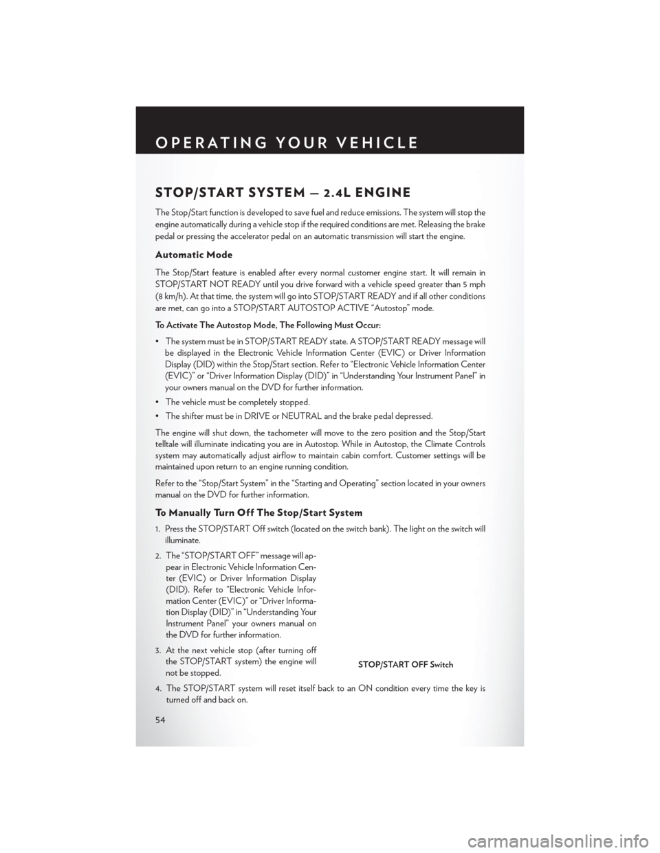
To Manually Turn Off The Stop/Start System
1. Press the STOP/START Off switch (located on the switch bank). The light on the switch will illuminate.
2. The “STOP/START OFF” message will ap- pear in Electronic Vehicle Information Cen-
ter (EVIC) or Driver Information Display
(DID). Refer to “Electronic Vehicle Infor-
mation Center (EVIC)” or “Driver Informa-
tion Display (DID)” in “Understanding Your
Instrument Panel” your owners manual on
the DVD for further information.
3. At the next vehicle stop (after turning off the STOP/START system) the engine will
not be stopped.
4. The STOP/START system will reset itself back to an ON condition every time the key is turned off and back on.
STOP/START OFF Switch
OPERATING YOUR VEHICLE
54
Page 57 of 220
To Manually Turn On The Stop/Start System
Press the STOP/START Off switch (located on the switch bank). The light on the switch will turn off.
For complete details on the Stop/Start System refer to the “Stop/Start System” in the “Starting
and Operating” section located in your owners manual on the DVD for further information.
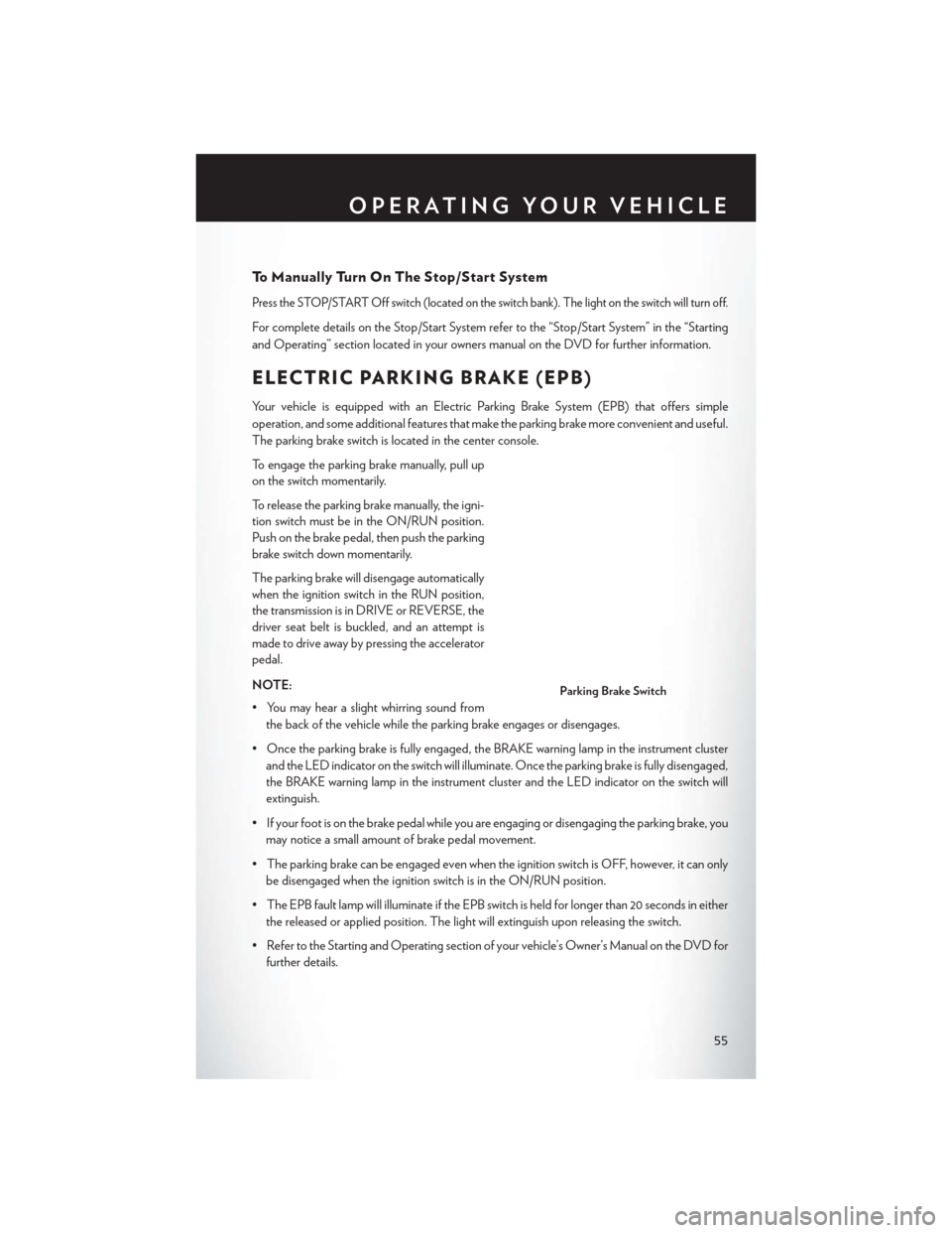
ELECTRIC PARKING BRAKE (EPB)
Your vehicle is equipped with an Electric Parking Brake System (EPB) that offers simple
operation, and some additional features that make the parking brake more convenient and useful.
The parking brake switch is located in the center console.
To engage the parking brake manually, pull up
on the switch momentarily.
To release the parking brake manually, the igni-
tion switch must be in the ON/RUN position.
Push on the brake pedal, then push the parking
brake switch down momentarily.
The parking brake will disengage automatically
when the ignition switch in the RUN position,
the transmission is in DRIVE or REVERSE, the
driver seat belt is buckled, and an attempt is
made to drive away by pressing the accelerator
pedal.
NOTE:
• You may hear a slight whirring sound fromthe back of the vehicle while the parking brake engages or disengages.
• Once the parking brake is fully engaged, the BRAKE warning lamp in the instrument cluster and the LED indicator on the switch will illuminate. Once the parking brake is fully disengaged,
the BRAKE warning lamp in the instrument cluster and the LED indicator on the switch will
extinguish.
• If your foot is on the brake pedal while you are engaging or disengaging the parking brake, you may notice a small amount of brake pedal movement.
• The parking brake can be engaged even when the ignition switch is OFF, however, it can only be disengaged when the ignition switch is in the ON/RUN position.
• The EPB fault lamp will illuminate if the EPB switch is held for longer than 20 seconds in either the released or applied position. The light will extinguish upon releasing the switch.
• Refer to the Starting and Operating section of your vehicle’s Owner’s Manual on the DVD for further details.
Parking Brake Switch
OPERATING YOUR VEHICLE
55
Page 58 of 220
CAUTION!
If the Brake System Warning Light remains on with the parking brake released, a brake system
malfunction is indicated. Have the brake system serviced by an authorized dealer immediately.
WARNING!
• Never use the PARK position as a substitute for the parking brake. Always apply theparking brake fully when parked to guard against vehicle movement and possible injury or
damage.
• When leaving the vehicle, always make sure the ignition is in the OFF position, remove the
key fob from the vehicle, and lock your vehicle.
• Never leave children alone in a vehicle, or with access to an unlocked vehicle. Allowing
children to be in a vehicle unattended is dangerous for a number of reasons. A child or
others could be seriously or fatally injured. Children should be warned not to touch the
parking brake, brake pedal or the transmission gear selector.
• Do not leave the Key Fob in or near the vehicle, (or in a location accessible to children),
and do not leave the ignition in the ACC or ON/RUN position. A child could operate
power windows, other controls, or move the vehicle.
• Be sure the parking brake is fully disengaged before driving; failure to do so can lead to
brake failure and a collision.
• Always fully apply the parking brake when leaving your vehicle, or it may roll and cause
damage or injury. Also be certain to leave the transmission in PARK. Failure to do so may
allow the vehicle to roll and cause damage or injury.
• Driving the vehicle with the parking brake engaged, or repeated use of the parking brake
to slow the vehicle may cause serious damage to the brake system.
OPERATING YOUR VEHICLE
56
Page 62 of 220
PARKVIEW® REAR BACK-UP CAMERA
You can see an on-screen image of the rear of your vehicle whenever the shift lever is put into
REVERSE. The ParkView® Rear Back-Up Camera image will be displayed on the radio display
screen, located on the center stack of the instrument panel.
If the radio display screen appears foggy, clean the camera lens located on the rear of the vehicle
above the rear license plate.
Refer to your Owner's Manual on the DVD for further details.
WARNING!
Drivers must be careful when backing up; even when using the ParkView® Rear Back-Up
Camera. Always check carefully behind your vehicle, and be sure to check for pedestrians,
animals, other vehicles, obstructions, or blind spots before backing up. You must continue to
pay attention while backing up. Failure to do so can result in serious injury or death.
BLIND SPOT MONITORING
The Blind Spot Monitoring (BSM) system uses two radar-based sensors, located inside the rear
bumper fascia, to detect Highway licensable vehicles (automobiles, trucks, motorcycles etc.) that
enter the blind spot zones from the rear/front/side of the vehicle.
The Blind Spot Monitoring (BSM) system warning light, located in the outside mirrors, will
illuminate if a vehicle moves into a blind spot zone.
The BSM system can also be configured to sound an audible (chime) alert and mute the radio to
notify you of objects that have entered the detection zones.
Refer to your Owner's Manual on the DVD for further details.
OPERATING YOUR VEHICLE
60
Page 71 of 220
3. The Uconnect® Access Registration App will open and display step-by-step instructions tostart your registration.
4. Enter your email address into the radio touchscreen.
5. A message will display on the touchscreen indicating your email submission was accepted. In a few minutes, you will receive an email which will allow you to register your vehicle for
Uconnect® Access. You should open this email and begin your Uconnect® Access registration
within 72 hours.
6. Check for an email from Uconnect® Access that contains your personalized registration link. If you don't see it, check your spam or junk mail folder. Open the email and click on the link to
continue registering.
NOTE:
For security reasons, this link is valid for 72 hours from the time you’ve submitted your email
address into the radio touchscreen. If the link has expired, simply re-enter your email address into
the Uconnect® Registration App on the radio touchscreen to receive another link. The secured
registration link will take you through the Uconnect® Access registration process step by step.
7. T
o unlock the full potential of Uconnect® Access in your vehicle, you will need to create or validate
an existing Mopar Owner Connect account previously (Owner Center). Uconnect® along with
Mopar Owner Connect have joined forces to create one destination to manage all of your vehicle
needs, from managing your Uconnect® Access account, to tracking service history and finding
recommended accessories for your vehicle. If you already have a Mopar Owner Connect account,
log in to the website with your existing username/email and password. For assistance with this web
based registration process, call Uconnect® Care at 1-855-792-4241.
8. Once you are logged in to your Mopar Owner Connect account, you will create a personal
Uconnect® Security PIN. The Uconnect® Security PIN will be required to authenticate you
when accessing your account via Uconnect® Care or performing any remote services such as
Remote Door Lock/Unlock, Remote Horn & Lights or Starting and Stopping the engine.
9. If your vehicle qualifies for a trial package it will be presented. Simply agree to the Uconnect® Terms of Service (checkbox) and then select the “Start Service” button.
At this point your vehicle is registered with Uconnect® Access. Continue to set up Via Mobile.
Apps will be downloaded the next time you start your vehicle. If the Apps have not appeared after
24 hours, please contact Uconnect® Care.
ELECTRONICS
69