CHRYSLER 200 2015 2.G Owner's Guide
Manufacturer: CHRYSLER, Model Year: 2015, Model line: 200, Model: CHRYSLER 200 2015 2.GPages: 220, PDF Size: 3.7 MB
Page 31 of 220
Rear Head Restraints
The rear outboard head restraints have three positions UP, MID and DOWN. The center head
restraint has only two positions, Up and Down. When the center seat is being occupied the head
restraint should be in the raised position. When there are no occupants in the center seat the head
restraint can be lowered for maximum visibility for the driver.
To raise the head restraint, pull upward on the head restraint. To lower the head restraint, press the
push button, located at the base of the head restraint, and push downward on the head restraint.
FRONT SEATS
Power Seats
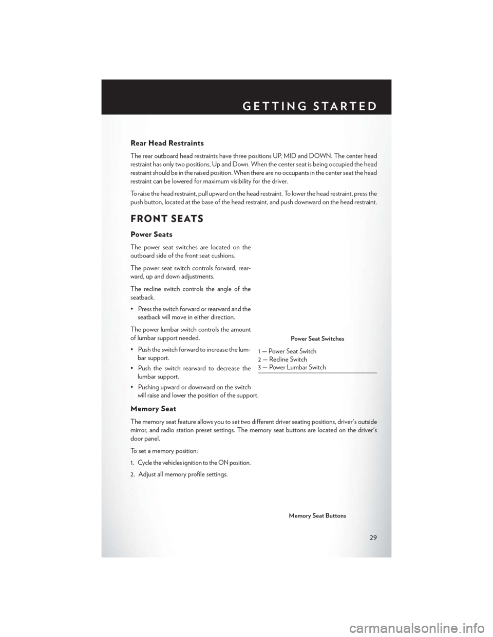
The power seat switches are located on the
outboard side of the front seat cushions.
The power seat switch controls forward, rear-
ward, up and down adjustments.
The recline switch controls the angle of the
seatback.
• Press the switch forward or rearward and theseatback will move in either direction.
The power lumbar switch controls the amount
of lumbar support needed.
• Push the switch forward to increase the lum- bar support.
• Push the switch rearward to decrease the lumbar support.
• Pushing upward or downward on the switch will raise and lower the position of the support.
Memory Seat
The memory seat feature allows you to set two different driver seating positions, driver's outside
mirror, and radio station preset settings. The memory seat buttons are located on the driver's
door panel.
To set a memory position:
1.
Cycle the vehicles ignition to the ON position.
2. Adjust all memory profile settings.
Power Seat Switches
1 — Power Seat Switch
2 — Recline Switch
3 — Power Lumbar Switch
Memory Seat Buttons
GETTING STARTED
29
Page 32 of 220
3. Press the S (SET) button then press the 1 or 2 button within five seconds. The ElectronicVehicle Information Center (EVIC) or Driver Information Display (DID) will display which
memory position is being set.
NOTE:
Before programming your RKE transmitters you must select the “Personal Settings Linked To
Fob” feature through the Uconnect® system. Refer to “Uconnect® Settings ” in “Understanding
Your Instrument Panel” in the Owner's Manual on the DVD for further details.
To program a Key Fob to the memory position:
1. Cycle the vehicles ignition to the OFF position.
2. Select the desired memory profile 1 or 2.
3. Press and release the SET button on the memory switch, then within five seconds press and release the button labeled 1 or 2 accordingly. “Memory Profile Set” (1 or 2) will display in the
EVIC/DID.
4. Press and release the LOCK button on the RKE transmitter within 10 seconds.
Easy Entry/Exit Feature
The memory seat has an Easy Entry/Exit feature. This feature provides automatic driver seat
positioning to enhance driver mobility when entering and exiting the vehicle.
NOTE:
The Easy Entry/Exit feature is not enabled when the vehicle is delivered from the factory. The
Easy Entry/Exit feature is enabled (or later disabled) through the programmable features in the
Uconnect® system. Refer to “Uconnect® Settings ” in “Understanding Your Instrument Panel” in
the Owner's Manual on the DVD for further details.
Manual Seat Adjustment
Forward/Rearward
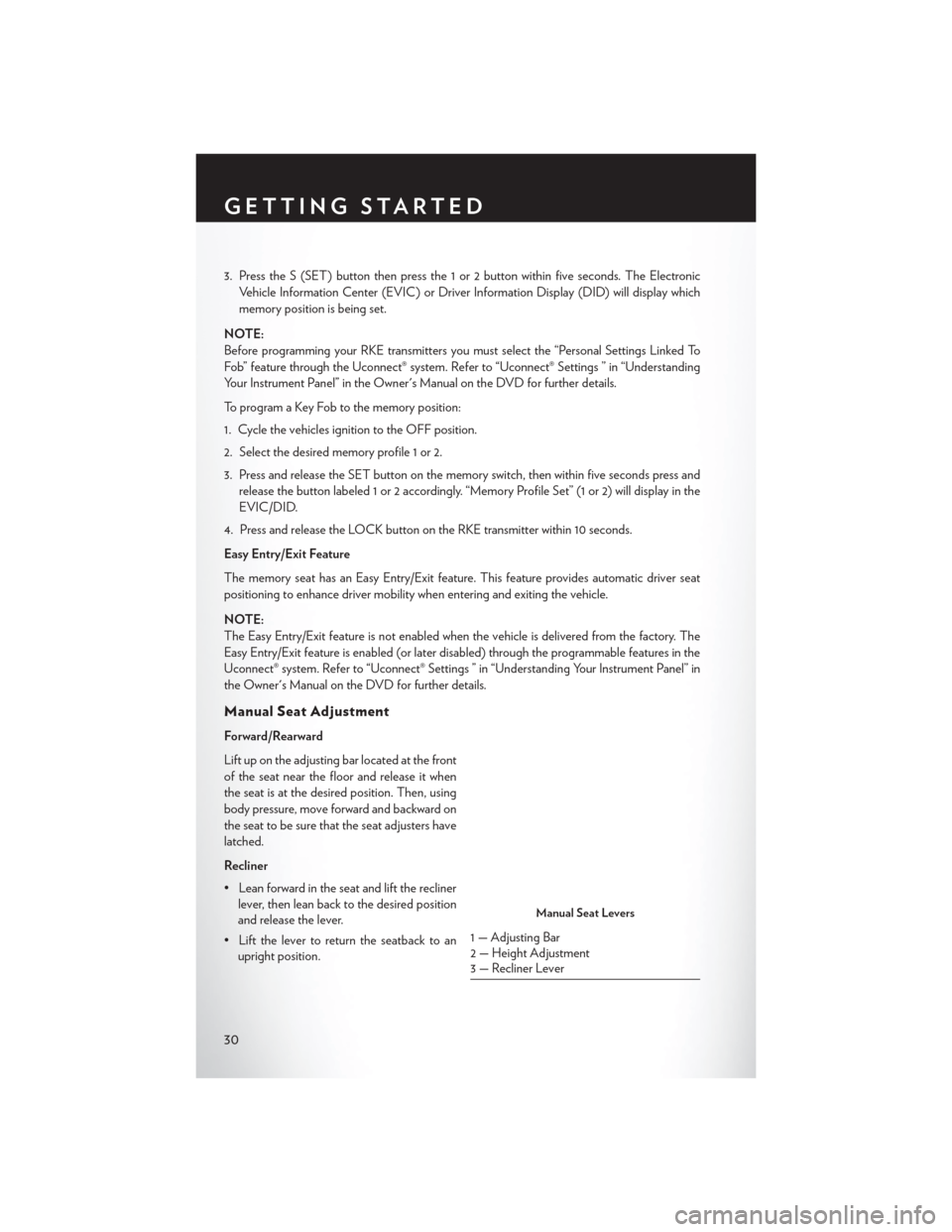
Lift up on the adjusting bar located at the front
of the seat near the floor and release it when
the seat is at the desired position. Then, using
body pressure, move forward and backward on
the seat to be sure that the seat adjusters have
latched.
Recliner
• Lean forward in the seat and lift the recliner lever, then lean back to the desired position
and release the lever.
• Lift the lever to return the seatback to an upright position.
Manual Seat Levers
1 — Adjusting Bar
2 — Height Adjustment
3 — Recliner Lever
GETTING STARTED
30
Page 33 of 220
Height Adjustment
• Ratchet the front lever, located on the outboard side of the seat, upward to raise the seatheight.
• Ratchet the lever downward to lower the seat height.
CAUTION!
Do not place any article under a power seat or impede its ability to move as it may cause
damage to the seat controls. Seat travel may become limited if movement is stopped by an
obstruction in the seat’s path.
WARNING!
• Adjusting a seat while the vehicle is moving is dangerous. The sudden movement of the seat could cause you to lose control. The seat belt might not be properly adjusted, and you
could be severely injured or killed. Only adjust a seat while the vehicle is parked.
• Do not ride with the seatback reclined so that the seat belt is no longer resting against your
chest. In a collision, you could slide under the seat belt and be severely injured or killed.
Use the recliner only when the vehicle is parked.
REAR SEAT
Folding Rear Seatback
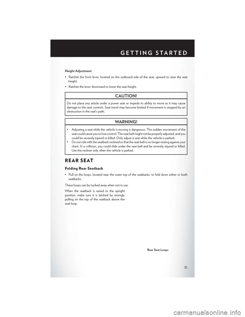
• Pull on the loops, located near the outer top of the seatbacks, to fold down either or both
seatbacks.
These loops can be tucked away when not in use.
When the seatback is raised to the upright
position, make sure it is latched by strongly
pulling on the top of the seatback above the
seat loop.
Rear Seat Loops
GETTING STARTED
31
Page 34 of 220
WARNING!
• Be certain that the seatback is securely locked into position. If the seatback is not securelylocked into position, the seat will not provide the proper stability for child seats and/or
passengers. An improperly latched seat could cause you and others to severely injured or
killed.
• The cargo area in the rear of the vehicle (with the rear seatbacks in the locked-up or
folded-down position) should not be used as a play area by children when the vehicle is in
motion. They could be severely injured or killed in a collision. Children should be seated
and using the proper restraint system.
HEATED/VENTILATED SEATS
Front Ventilated Seats
Located in the seat cushion and seatback are small fans that draw the air from the passenger
compartment and pull air through fine perforations in the seat cover to help keep the driver and
front passenger cooler in higher ambient temperatures.
There are two ventilated seat control buttons located in the touchscreen that allow the driver and
passenger to operate the seats independently.
The ventilated seat buttons are used to control the speed of the fans located in the seat.
To operate the system, press the “Controls” button on touchscreen located on the bottom of the
Uconnect® display.
• Press the ventilated seat button
once to choose HIGH.
• Press the ventilated seat button
a second time to choose LOW.
• Press the ventilated seat button
a third time to turn the ventilated seat OFF.
NOTE:
Vehicle Equipped With Remote Start
On models that are equipped with remote start, this feature can be programmed to come on
during a remote start through the Uconnect® system. Refer to “Uconnect® Settings” in “Under-
standing Your Instrument Panel” in the Owner's Manual on the DVD.
Front Heated Seats
The front heated seats control buttons are located within the climate or controls screen of the
touchscreen.
• Press the heated seat button
once to turn the High setting On.
• Press the heated seat button
a second time to turn the Low setting On.
• Press the heated seat button
a third time to turn the heating elements Off.
If the High-level setting is selected, the system will automatically switch to Low-level after
approximately 60 minutes. The Low-level setting will turn Off automatically after approximately
45 minutes.
GETTING STARTED
32
Page 35 of 220
NOTE:
Vehicle Equipped With Remote Start
On models that are equipped with remote start, this feature can be programmed to come on
during a remote start through the Uconnect® system. Refer to “Uconnect® Settings” in “Under-
standing Your Instrument Panel” in the Owner's Manual on the DVD.
WARNING!
• Persons who are unable to feel pain to the skin because of advanced age, chronic illness,diabetes, spinal cord injury, medication, alcohol use, exhaustion or other physical condi-
tions must exercise care when using the seat heater. It may cause burns even at low
temperatures, especially if used for long periods of time.
• Do not place anything on the seat that insulates against heat, such as a blanket or cushion.
This may cause the seat heater to overheat. Sitting in a seat that has been overheated
could cause serious burns due to the increased surface temperature of the seat.
HEATED STEERING WHEEL
The steering wheel contains a heating element that heats the steering wheel to one temperature
setting.
The heated steering wheel control button is located within the Uconnect® system. You can gain
access to the control buttons through the climate screen or the controls screen.
• Press the heated steering wheel button
once to turn the heating element ON.
• Press the heated steering wheel button
a second time to turn the heating element OFF.
Once the heated steering wheel has been turned on, it will operate for up to 80 minutes before
automatically shutting off. The heated steering wheel can shut off early or may not turn on when
the steering wheel is already warm.
NOTE:
Vehicle Equipped With Remote Start
On models that are equipped with remote start, this feature can be programmed to come on
during a remote start through the Uconnect® system. Refer to “Uconnect® Settings” in “Under-
standing Your Instrument Panel” in the Owner's Manual on the DVD.
WARNING!
• Persons who are unable to feel pain to the skin because of advanced age, chronic illness, diabetes, spinal cord injury, medication, alcohol use, exhaustion, or other physical condi-
tions must exercise care when using the steering wheel heater. It may cause burns even at
low temperatures, especially if used for long periods.
• Do not place anything on the steering wheel that insulates against heat, such as a blanket
or steering wheel covers of any type and material. This may cause the steering wheel
heater to overheat.
GETTING STARTED
33
Page 36 of 220
TILT/TELESCOPING STEERING COLUMN
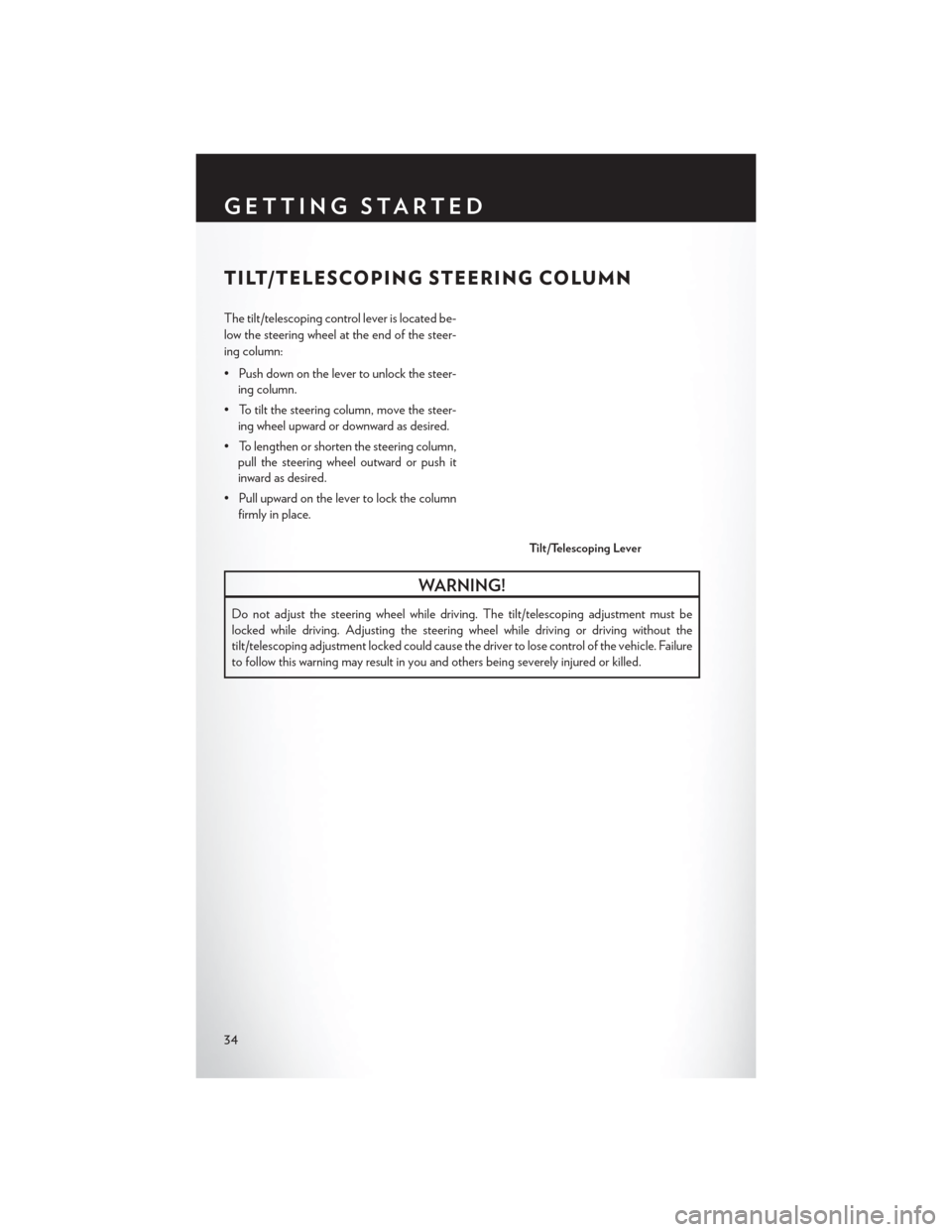
The tilt/telescoping control lever is located be-
low the steering wheel at the end of the steer-
ing column:
• Push down on the lever to unlock the steer-ing column.
• To tilt the steering column, move the steer- ing wheel upward or downward as desired.
• To lengthen or shorten the steering column, pull the steering wheel outward or push it
inward as desired.
• Pull upward on the lever to lock the column firmly in place.
WARNING!
Do not adjust the steering wheel while driving. The tilt/telescoping adjustment must be
locked while driving. Adjusting the steering wheel while driving or driving without the
tilt/telescoping adjustment locked could cause the driver to lose control of the vehicle. Failure
to follow this warning may result in you and others being severely injured or killed.
Tilt/Telescoping Lever
GETTING STARTED
34
Page 37 of 220
ENGINE BREAK-IN RECOMMENDATIONS
A long break-in period is not required for the engine and drivetrain (transmission and axle) in your
vehicle.
Drive moderately during the first 300 miles (500 km). After the initial 60 miles (100 km), speeds
up to 50 or 55 mph (80 or 90 km/h) are desirable.
While cruising, brief full-throttle acceleration within the limits of local traffic laws contributes to a
good break-in. Wide-open throttle acceleration in low gear can be detrimental and should be
avoided.
The engine oil installed in the engine at the factory is a high-quality energy conserving type
lubricant. Oil changes should be consistent with anticipated climate conditions under which
vehicle operations will occur. For the recommended viscosity and quality grades, refer to
“Maintaining Your Vehicle.”
NOTE:
A new engine may consume some oil during its first few thousand miles (kilometers) of opera-
tion. This should be considered a normal part of the break-in and not interpreted as an indica-
tion of an engine problem or malfunction.
CAUTION!
Never use Non-Detergent Oil or Straight Mineral Oil in the engine or damage may result.
TURN SIGNAL/HIGH BEAM LEVER
Turn Signals/Lane Change Assist
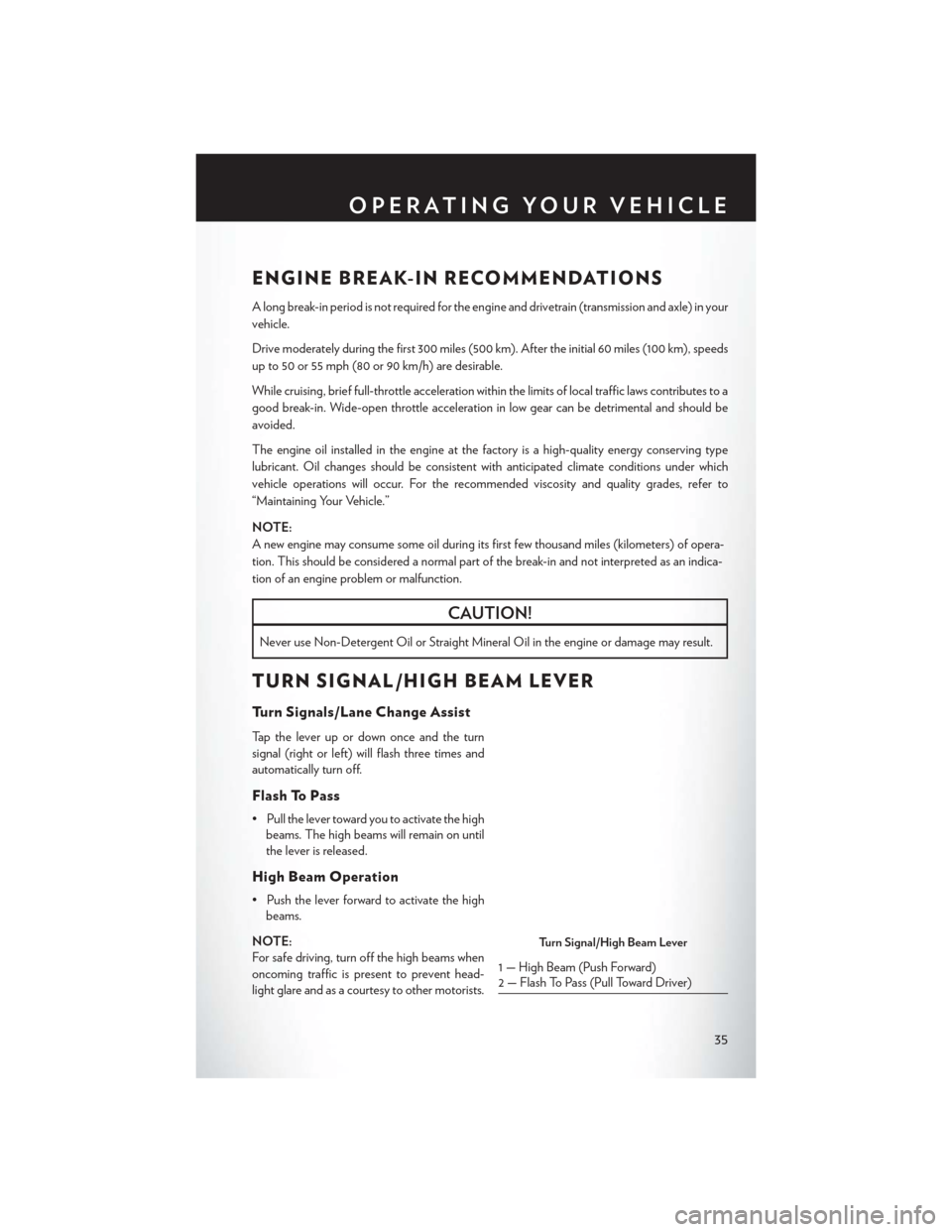
Tap the lever up or down once and the turn
signal (right or left) will flash three times and
automatically turn off.
Flash To Pass
• Pull the lever toward you to activate the highbeams. The high beams will remain on until
the lever is released.
High Beam Operation
• Push the lever forward to activate the highbeams.
NOTE:
For safe driving, turn off the high beams when
oncoming traffic is present to prevent head-
light glare and as a courtesy to other motorists.
Turn Signal/High Beam Lever
1 — High Beam (Push Forward)
2 — Flash To Pass (Pull Toward Driver)
OPERATING YOUR VEHICLE
35
Page 38 of 220
HEADLIGHT SWITCH
Automatic Headlights/Parking
Lights/Headlights
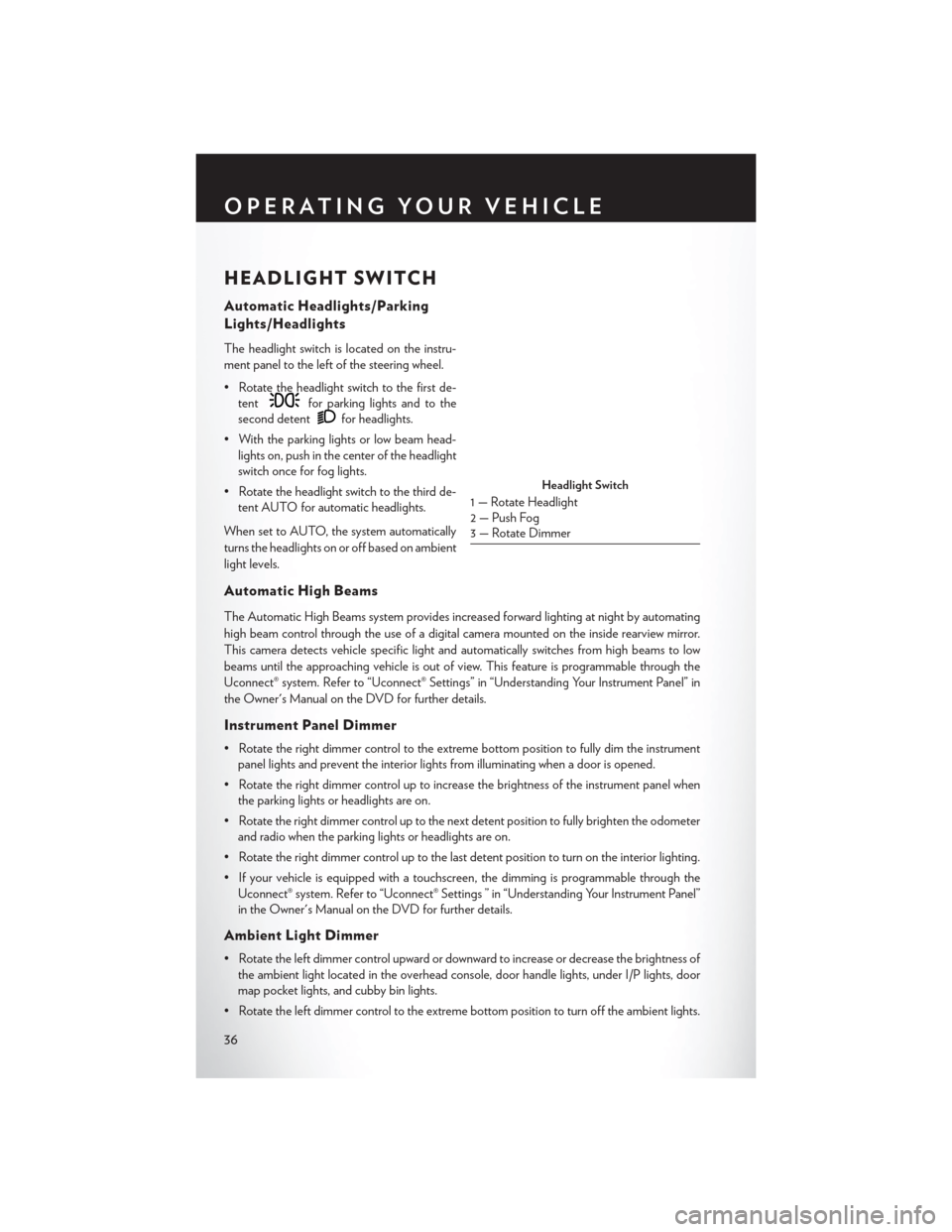
The headlight switch is located on the instru-
ment panel to the left of the steering wheel.
• Rotate the headlight switch to the first de-tent
for parking lights and to the
second detent
for headlights.
• With the parking lights or low beam head- lights on, push in the center of the headlight
switch once for fog lights.
• Rotate the headlight switch to the third de- tent AUTO for automatic headlights.
When set to AUTO, the system automatically
turns the headlights on or off based on ambient
light levels.
Automatic High Beams
The Automatic High Beams system provides increased forward lighting at night by automating
high beam control through the use of a digital camera mounted on the inside rearview mirror.
This camera detects vehicle specific light and automatically switches from high beams to low
beams until the approaching vehicle is out of view. This feature is programmable through the
Uconnect® system. Refer to “Uconnect® Settings” in “Understanding Your Instrument Panel” in
the Owner's Manual on the DVD for further details.
Instrument Panel Dimmer
• Rotate the right dimmer control to the extreme bottom position to fully dim the instrument panel lights and prevent the interior lights from illuminating when a door is opened.
• Rotate the right dimmer control up to increase the brightness of the instrument panel when the parking lights or headlights are on.
• Rotate the right dimmer control up to the next detent position to fully brighten the odometer and radio when the parking lights or headlights are on.
• Rotate the right dimmer control up to the last detent position to turn on the interior lighting.
• If your vehicle is equipped with a touchscreen, the dimming is programmable through the Uconnect® system. Refer to “Uconnect® Settings ” in “Understanding Your Instrument Panel”
in the Owner's Manual on the DVD for further details.
Ambient Light Dimmer
• Rotate the left dimmer control upward or downward to increase or decrease the brightness ofthe ambient light located in the overhead console, door handle lights, under I/P lights, door
map pocket lights, and cubby bin lights.
• Rotate the left dimmer control to the extreme bottom position to turn off the ambient lights.
Headlight Switch
1 — Rotate Headlight
2 — Push Fog
3 — Rotate Dimmer
OPERATING YOUR VEHICLE
36
Page 39 of 220
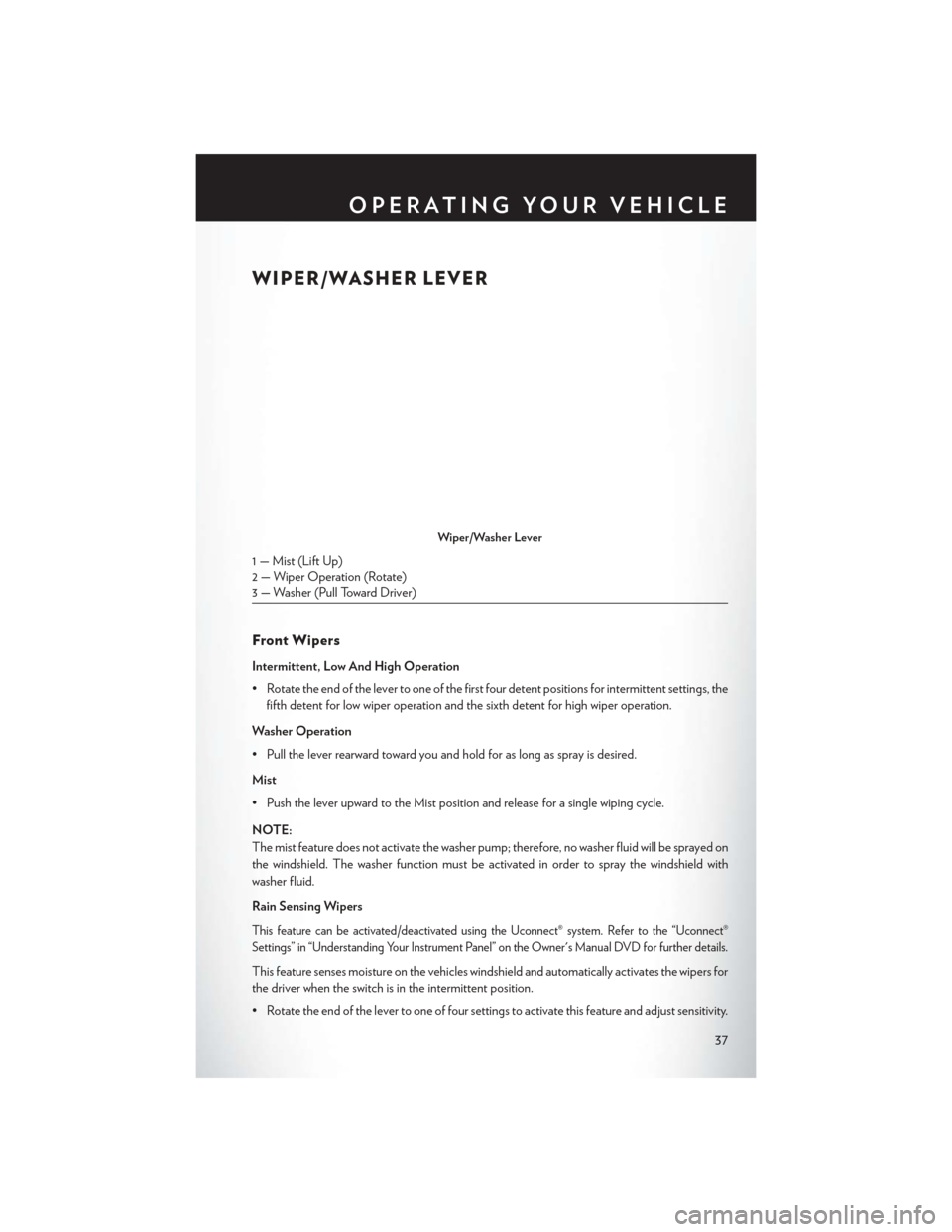
WIPER/WASHER LEVER
Front Wipers
Intermittent, Low And High Operation
• Rotate the end of the lever to one of the first four detent positions for intermittent settings, thefifth detent for low wiper operation and the sixth detent for high wiper operation.
Washer Operation
• Pull the lever rearward toward you and hold for as long as spray is desired.
Mist
• Push the lever upward to the Mist position and release for a single wiping cycle.
NOTE:
The mist feature does not activate the washer pump; therefore, no washer fluid will be sprayed on
the windshield. The washer function must be activated in order to spray the windshield with
washer fluid.
Rain Sensing Wipers
This feature can be activated/deactivated using the Uconnect® system. Refer to the “Uconnect®
Settings” in “Understanding Your Instrument Panel” on the Owner's Manual DVD for further details.
This feature senses moisture on the vehicles windshield and automatically activates the wipers for
the driver when the switch is in the intermittent position.
• Rotate the end of the lever to one of four settings to activate this feature and adjust sensitivity.
Wiper/Washer Lever
1 — Mist (Lift Up)
2 — Wiper Operation (Rotate)
3 — Washer (Pull Toward Driver)
OPERATING YOUR VEHICLE
37
Page 40 of 220
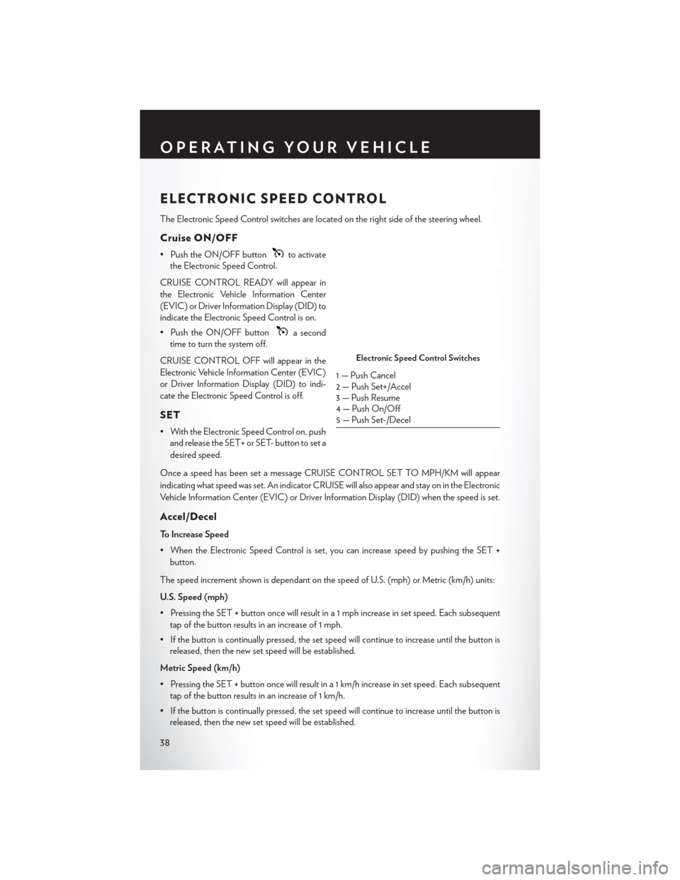
ELECTRONIC SPEED CONTROL
The Electronic Speed Control switches are located on the right side of the steering wheel.
Cruise ON/OFF
• Push the ON/OFF buttonto activate
the Electronic Speed Control.
CRUISE CONTROL READY will appear in
the Electronic Vehicle Information Center
(EVIC) or Driver Information Display (DID) to
indicate the Electronic Speed Control is on.
• Push the ON/OFF button
a second
time to turn the system off.
CRUISE CONTROL OFF will appear in the
Electronic Vehicle Information Center (EVIC)
or Driver Information Display (DID) to indi-
cate the Electronic Speed Control is off.
SET
• With the Electronic Speed Control on, push and release the SET+ or SET- button to set a
desired speed.
Once a speed has been set a message CRUISE CONTROL SET TO MPH/KM will appear
indicating what speed was set. An indicator CRUISE will also appear and stay on in the Electronic
Vehicle Information Center (EVIC) or Driver Information Display (DID) when the speed is set.
Accel/Decel
To Increase Speed
• When the Electronic Speed Control is set, you can increase speed by pushing the SET +
button.
The speed increment shown is dependant on the speed of U.S. (mph) or Metric (km/h) units:
U.S. Speed (mph)
• Pressing the SET +button once will result in a 1 mph increase in set speed. Each subsequent
tap of the button results in an increase of 1 mph.
• If the button is continually pressed, the set speed will continue to increase until the button is released, then the new set speed will be established.
Metric Speed (km/h)
• Pressing the SET +button once will result in a 1 km/h increase in set speed. Each subsequent
tap of the button results in an increase of 1 km/h.
• If the button is continually pressed, the set speed will continue to increase until the button is released, then the new set speed will be established.
Electronic Speed Control Switches
1 — Push Cancel
2 — Push Set+/Accel
3 — Push Resume
4 — Push On/Off
5 — Push Set-/Decel
OPERATING YOUR VEHICLE
38