lock CHRYSLER 200 2015 2.G Owner's Guide
[x] Cancel search | Manufacturer: CHRYSLER, Model Year: 2015, Model line: 200, Model: CHRYSLER 200 2015 2.GPages: 220, PDF Size: 3.7 MB
Page 136 of 220
• Press “Jump” to activate the feature. After listening to Traffic and Weather, press “Jump” againto return to the previous channel.
Fav
Activates the favorites menu. You can add up to 50 favorite artists or songs.
• Just press Add Fav Artist or Add Fav Song while the song is playing. You will then be alerted any time one of these songs, or works by these artists, is playing on other SiriusXM channels.
SiriusXM Parental Controls
You can skip or hide certain channels from view if you do not want access to them.
• Press the “More” button on the touchscreen, then the “Settings” button on the touchscreen, next press the “Sirius Setup” button on the touchscreen, then select “Channel Skip”. Press the
box, check-mark, next to the channel you want skipped. They will not show up in normal usage.
SiriusXM also offers the option to permanently block selected channels. Call (1-888-601-6297 for U.S.
customers, 1-877-438-9677 for Canadian customers) and request the Family-Friendly Package.
Browse
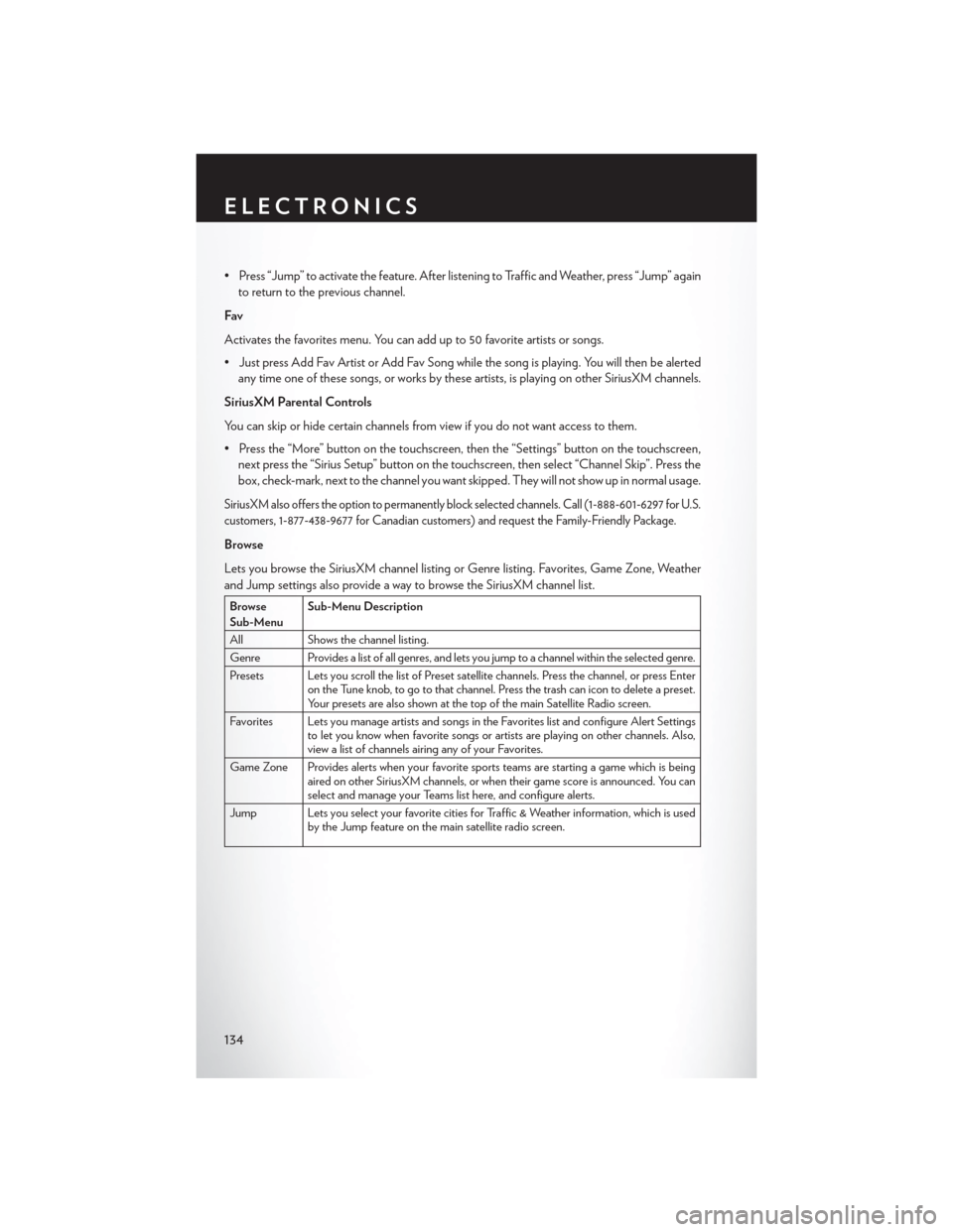
Lets you browse the SiriusXM channel listing or Genre listing. Favorites, Game Zone, Weather
and Jump settings also provide a way to browse the SiriusXM channel list.
Browse
Sub-Menu Sub-Menu Description
All Shows the channel listing.
Genre Provides a list of all genres, and lets you jump to a channel within the selected genre.
Presets Lets you scroll the list of Preset satellite channels. Press the channel, or press Enter on the Tune knob, to go to that channel. Press the trash can icon to delete a preset.
Your presets are also shown at the top of the main Satellite Radio screen.
Favorites Lets you manage artists and songs in the Favorites list and configure Alert Settings to let you know when favorite songs or artists are playing on other channels. Also,
view a list of channels airing any of your Favorites.
Game Zone Provides alerts when your favorite sports teams are starting a game which is being aired on other SiriusXM channels, or when their game score is announced. You can
select and manage your Teams list here, and configure alerts.
Jump Lets you select your favorite cities for Traffic & Weather information, which is used by the Jump feature on the main satellite radio screen.
ELECTRONICS
134
Page 150 of 220
PROGRAMMABLE FEATURES
Uconnect® Customer Programmable Features
The Uconnect® system allows you to access Customer Programmable feature settings such as
Display, Clock, Safety/Assistance, Lights, Doors & Locks, Auto-On Comfort & Remote Start,
Engine Off Operation, Compass Settings, Audio, Trailer Brake, Phone/Bluetooth®, Suspension
and SiriusXM Setup and System Information through buttons on the touchscreen.
• Push the “Controls” button located near the bottom of the touchscreen, then push the“Settings” button on the touchscreen to access the Settings screen. When making a selection,
scroll up or down until the preferred setting is highlighted, then press and release the preferred
setting until a check-mark appears next to the setting, showing that setting has been selected.
The following feature settings are available:
• Display • Voice
• Units • Doors & Locks
• Safety/Assistance • Engine Off Options
• Auto-On Comfort & Remote Start • Audio
• Phone/Bluetooth® • SiriusXM Setup
• Lights • System Information
• Clock • Compass
Refer to “Uconnect Settings/Customer Programmable Features” found within “Understanding
Your Instrument Panel” located in your Owner's Manual on the DVD for further information.
UNIVERSAL GARAGE DOOR OPENER
(HomeLink®)
HomeLink® replaces up to three hand-held
transmitters that operate devices such as ga-
rage door openers, motorized gates, lighting or
home security systems. The HomeLink® unit is
powered by your vehicles 12 Volt battery.
The HomeLink® buttons that are located in the
overhead console or sunvisor designate the
three different HomeLink® channels.
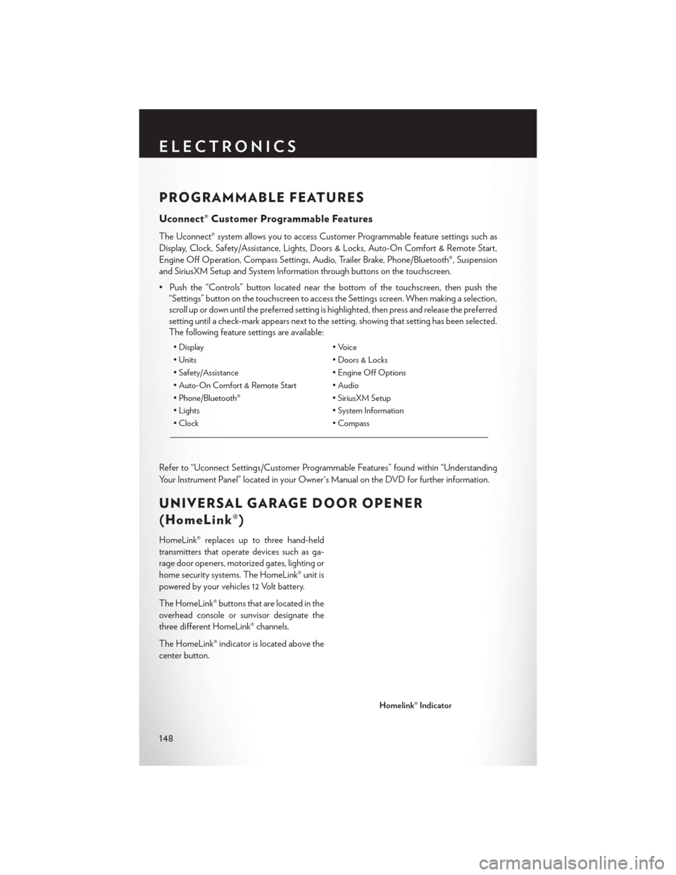
The HomeLink® indicator is located above the
center button.
Homelink® Indicator
ELECTRONICS
148
Page 152 of 220
NOTE:
If the device does not activate, push the button a third time (for two seconds) to complete the
training.
7. To program the remaining two HomeLink® buttons, repeat each step for each remainingbutton. DO NOT erase the channels.
Programming A Non-Rolling Code
NOTE:
For programming Garage Door Openers manufactured before 1995.
1. Turn the ignition switch to the ON/RUN position.
2. Place the hand-held transmitter 1 to 3 inches (3 to 8 cm) away from the HomeLink® button you wish to program while keeping the HomeLink® indicator light in view.
3. Push and hold the HomeLink® button you want to program while you push and hold the hand-held transmitter button.
4. Continue to hold both buttons and observe the indicator light. The HomeLink® indicator will flash slowly and then rapidly after HomeLink® has received the frequency signal from the
hand-held transmitter. Release both buttons after the indicator light changes from slow to
rapid.
5. Push and hold the programmed HomeLink® button and observe the indicator light. If the indicator light stays on constantly, programming is complete and the garage door (or device)
should activate when the HomeLink® button is pushed.
6. To program the two remaining HomeLink® buttons, repeat each step for each remaining button. DO NOT erase the channels.
Using HomeLink®
To operate, push and release the programmed HomeLink® button. Activation will now occur for the
programmed device (i.e., garage door opener, gate operator, security system, entry door lock,
home/office lighting, etc.,). The hand-held transmitter of the device may also be used at any time.
WARNING!
•Your motorized door or gate will open and close while you are programming the universal
transceiver. Do not program the transceiver if people or pets are in the path of the door or gate.
• Do not run your vehicle in a closed garage or confined area while programming the transceiver. Exhaust gas from your vehicle contains Carbon Monoxide (CO) which is
odorless and colorless. Carbon Monoxide is poisonous when inhaled and can cause you
and others to be severely injured or killed.
ELECTRONICS
150
Page 157 of 220
ROADSIDE ASSISTANCE
Dial toll-free 1-800-521-2779 for U.S. Residents or 1-800-363-4869 for Canadian Residents.
• Provide your name, vehicle identification number, license plate number, and your location,including the telephone number from which you are calling.
• Briefly describe the nature of the problem and answer a few simple questions.
• You will be given the name of the service provider and an estimated time of arrival. If you feel you are in an “unsafe situation”, please let us know. With your consent, we will contact local
police or safety authorities.
INSTRUMENT CLUSTER WARNING LIGHTS
- Charging System Light
This light shows the status of the electrical charging system. If the charging system light remains
on, it means that the vehicle is experiencing a problem with the charging system.
We recommend you do not continue driving if the charging system light is on. Have the vehicle
serviced immediately.
- Oil Pressure Warning Light
This light indicates low engine oil pressure. If the light turns on while driving, stop the vehicle and
shut off the engine as soon as possible. A chime will sound when this light turns on.
We recommend you do not operate the vehicle or engine damage will occur. Have the vehicle
serviced immediately.
- Anti-Lock Brake (ABS) Light
This light monitors the Anti-Lock Brake System (ABS).
If the light is not on during starting, stays on, or turns on while driving, we recommend you contact
the nearest authorized dealer and have the vehicle serviced immediately.
- Air Bag Warning Light
This light will turn on for four to eight seconds as a bulb check when the ignition switch is first
turned to the ON/RUN position. If the light is either not on during starting, stays on, or turns on
while driving, have the system inspected at an authorized dealer as soon as possible. Refer to
“Occupant Restraints” in “Things To Know Before Starting Your Vehicle” of your Owner’s Manual
for further information.
NOTE:
The Air Bag System is designed to be maintenance free.
WHAT TO DO IN EMERGENCIES
155
Page 160 of 220
WARNING!
If you continue operating the vehicle when the Transmission Temperature Warning Light is
illuminated you could cause the fluid to boil over, come in contact with hot engine or exhaust
components and cause a fire.
- Seat Belt Reminder Light
When the ignition switch is first turned to ON/RUN, this light will turn on if the driver’s seat belt
is unbuckled, a chime will sound. When driving, if the driver’s seat belt remains unbuckled, the
Seat Belt Reminder Light will illuminate and the chime will sound.
Please have your vehicle serviced immediately.
WARNING!
Driving a vehicle with the red brake light on is dangerous. Part of the brake system may have
failed. It will take longer to stop the vehicle. You could have a collision. Have the vehicle
checked immediately.
- Brake Warning Light
This light monitors various brake functions, including brake fluid level and parking brake appli-
cation. If the brake light turns on it may indicate that the parking brake is applied, that the brake
fluid level is low, or that there is a problem with the anti-lock brake system reservoir.
If the light remains on when the parking brake has been disengaged, and the fluid level is at the
full mark on the master cylinder reservoir, it indicates a possible brake hydraulic system malfunc-
tion or that a problem with the Brake Booster has been detected by the Anti-Lock Brake System
(ABS)/Electronic Stability Control (ESC) system. In this case, the light will remain on until the
condition has been corrected. If the problem is related to the brake booster, the ABS pump will
run when applying the brake and a brake pedal pulsation may be felt during each stop.
The dual brake system provides a reserve braking capacity in the event of a failure to a portion of
the hydraulic system. A leak in either half of the dual brake system is indicated by the Brake
Warning Light, which will turn on when the brake fluid level in the master cylinder has dropped
below a specified level. The light will remain on until the cause is corrected.
Vehicles equipped with the Anti-Lock Brake System (ABS), are also equipped with Electronic
Brake Force Distribution (EBD). In the event of an EBD failure, the Brake Warning Light will turn
on along with the ABS Light. Immediate repair to the ABS system is required.
Operation of the Brake Warning Light can be checked by turning the ignition switch from the
OFF position to the ON/RUN position. The light should illuminate for approximately two
seconds. The light should then turn off unless the parking brake is applied or a brake fault is
detected. If the light does not illuminate, have the light inspected by an authorized dealer.
The light also will turn on when the parking brake is applied with the ignition switch in the
ON/RUN position.
WHAT TO DO IN EMERGENCIES
158
Page 168 of 220
(E) After Driving:
Pull over to a safe location. Refer to “Whenever You Stop to Use Tire Service Kit” before
continuing.
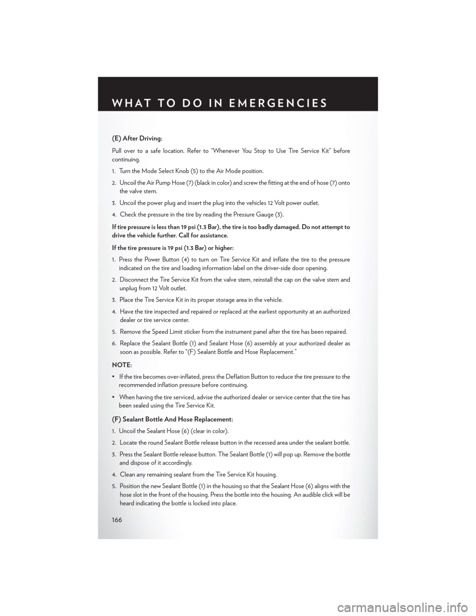
1. Turn the Mode Select Knob (5) to the Air Mode position.
2. Uncoil the Air Pump Hose (7) (black in color) and screw the fitting at the end of hose (7) ontothe valve stem.
3. Uncoil the power plug and insert the plug into the vehicles 12 Volt power outlet.
4. Check the pressure in the tire by reading the Pressure Gauge (3).
If tire pressure is less than 19 psi (1.3 Bar), the tire is too badly damaged. Do not attempt to
drive the vehicle further. Call for assistance.
If the tire pressure is 19 psi (1.3 Bar) or higher:
1. Press the Power Button (4) to turn on Tire Service Kit and inflate the tire to the pressure indicated on the tire and loading information label on the driver-side door opening.
2. Disconnect the Tire Service Kit from the valve stem, reinstall the cap on the valve stem and unplug from 12 Volt outlet.
3. Place the Tire Service Kit in its proper storage area in the vehicle.
4. Have the tire inspected and repaired or replaced at the earliest opportunity at an authorized dealer or tire service center.
5. Remove the Speed Limit sticker from the instrument panel after the tire has been repaired.
6. Replace the Sealant Bottle (1) and Sealant Hose (6) assembly at your authorized dealer as soon as possible. Refer to “(F) Sealant Bottle and Hose Replacement.”
NOTE:
• If the tire becomes over-inflated, press the Deflation Button to reduce the tire pressure to the recommended inflation pressure before continuing.
• When having the tire serviced, advise the authorized dealer or service center that the tire has been sealed using the Tire Service Kit.
(F) Sealant Bottle And Hose Replacement:
1. Uncoil the Sealant Hose (6) (clear in color).
2. Locate the round Sealant Bottle release button in the recessed area under the sealant bottle.
3. Press the Sealant Bottle release button. The Sealant Bottle (1) will pop up. Remove the bottle
and dispose of it accordingly.
4. Clean any remaining sealant from the Tire Service Kit housing.
5. Position the new Sealant Bottle (1) in the housing so that the Sealant Hose (6) aligns with the hose slot in the front of the housing. Press the bottle into the housing. An audible click will be
heard indicating the bottle is locked into place.
WHAT TO DO IN EMERGENCIES
166
Page 176 of 220
9. Finish tightening the lug bolts. Push down on the wrench while at the end of the handle forincreased leverage. Tighten the lug bolts in a star pattern until each nut has been tightened
twice. The correct wheel bolt tightness is 100 ft lb (135 N·m). If in doubt about the correct
tightness, have them checked with a torque wrench by your authorized dealer or at a service
station.
10. Lower the jack to its fully closed position.
11. Secure the tire, jack, and tools in their proper locations.
12. Remove chocks from wheels.
Road Tire Installation
1. Mount the road tire on the axle.
2. Install the remaining lug bolts with the threaded end of the bolt toward the wheel. Lightly tighten the lug bolts.
3. Lower the vehicle to the ground by turning the jack handle counterclockwise.
4. Finish tightening the lug bolts. Push down on the wrench while at the end of the handle for increased leverage. Tighten the lug bolts in a star pattern until each bolt has been tightened
twice. The correct tightness of each lug bolt is 100 ft/lbs (135 N·m). If in doubt about the
correct tightness, have them checked with a torque wrench by your authorized dealer or
service station.
5. After 25 miles (40 km) check the lug bolt torque with a torque wrench to ensure that all lug bolts are properly seated against the wheel.
CAUTION!
Do not attempt to raise the vehicle by jacking on locations other than those indicated in the
Jacking Instructions for this vehicle.
WHAT TO DO IN EMERGENCIES
174
Page 178 of 220
JUMP-STARTING
If your vehicle has a discharged battery it can be jump-started using a set of jumper cables and a
battery in another vehicle or by using a portable battery booster pack.
Jump-starting can be dangerous if done improperly so please follow the procedures in this
section carefully.
NOTE:
When using a portable battery booster pack follow the manufacturer’s operating instructions and
precautions.
Preparations For Jump-Start
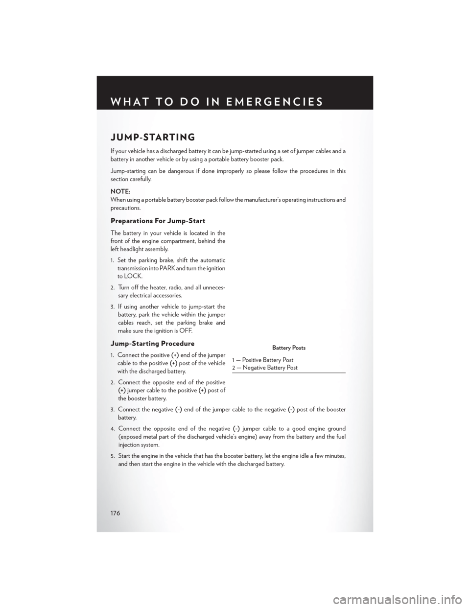
The battery in your vehicle is located in the
front of the engine compartment, behind the
left headlight assembly.
1. Set the parking brake, shift the automatictransmission into PARK and turn the ignition
to LOCK.
2. Turn off the heater, radio, and all unneces- sary electrical accessories.
3. If using another vehicle to jump-start the battery, park the vehicle within the jumper
cables reach, set the parking brake and
make sure the ignition is OFF.
Jump-Starting Procedure
1. Connect the positive (+)end of the jumper
cable to the positive (+)post of the vehicle
with the discharged battery.
2. Connect the opposite end of the positive (+) jumper cable to the positive (+)post of
the booster battery.
3. Connect the negative (-)end of the jumper cable to the negative (-)post of the booster
battery.
4. Connect the opposite end of the negative (-)jumper cable to a good engine ground
(exposed metal part of the discharged vehicle’s engine) away from the battery and the fuel
injection system.
5. Start the engine in the vehicle that has the booster battery, let the engine idle a few minutes, and then start the engine in the vehicle with the discharged battery.Battery Posts
1 — Positive Battery Post
2 — Negative Battery Post
WHAT TO DO IN EMERGENCIES
176
Page 182 of 220
2. Using a small screwdriver or similar tool, remove the Manual Park Release access cover, whichis underneath the rubber storage bin liner in the center console pass-through.
3. Unsnap the tether from the Manual Park Release lever.
4. Pull the tether upwards and rearward, until it locks vertically in place. Verify that the Manual Park Release lever is locked in the released position.
5. The vehicle is now out of PARK and can be moved. Release the parking brake only
when the vehicle is securely connected to a
tow vehicle.
Follow these steps to reset the Manual Park
Release:
1. Pull the tether upwards to unlock the lever.
2. Rotate the Manual Park Release lever for- ward and down to its original position.
3. Re-install the access cover and the rubber storage bin liner.
Manual Park Release Cover
Manual Park Release Tether
Locked Position
WHAT TO DO IN EMERGENCIES
180
Page 185 of 220
2. Move to the front of the vehicle.
3. Reach under the center front edge of thehood and push and hold the safety latch
lever to the right.
4. Lift the hood upward to the open position.
WARNING!
Be sure the hood is fully latched before driving your vehicle. If the hood is not fully latched, it
could open when the vehicle is in motion and block your vision. Failure to follow this warning
could result in serious injury or death.
Safety Latch Lever
MAINTAINING YOUR VEHICLE
183