clock CHRYSLER 200 CONVERTIBLE 2014 1.G User Guide
[x] Cancel search | Manufacturer: CHRYSLER, Model Year: 2014, Model line: 200 CONVERTIBLE, Model: CHRYSLER 200 CONVERTIBLE 2014 1.GPages: 124, PDF Size: 3.31 MB
Page 3 of 124
INTRODUCTION/WELCOME
WELCOME FROM CHRYSLER GROUP LLC..2
CONTROLS AT A GLANCE
DRIVER COCKPIT...............4
INSTRUMENT CLUSTER ...........6
GETTING STARTED
KEYFOB ....................8
REMOTE START................9
THEFT ALARM . ...............10
SUPPLEMENTAL RESTRAINT SYSTEM (SRS)
—AIRBAGS ..................11
CHILD RESTRAINTS .............12
SEATBELT ...................16
FRONTSEATS .................17
HEATEDSEATS ................19
TILT/TELESCOPING STEERING COLUMN..20
OPERATING YOUR VEHICLE
ENGINE BREAK-IN
RECOMMENDATIONS ............21
TURN SIGNAL/LIGHTS LEVER . ......22
WIPER/WASHER LEVER ...........23
SPEED CONTROL ..............24
MANUAL CLIMATE CONTROLS .....25
AUTOMATIC TEMPERATURE CONTROLS
(ATC) .....................26
POWER CONVERTIBLE TOP
OPERATION .................27
WIND BUFFETING ..............29
ELECTRONICS
YOUR VEHICLE'S SOUND SYSTEM ....30
Uconnect® 130 ..................32
Uconnect® 130 WITH SiriusXM SATELLITE
RADIO .....................34
Uconnect® 430/430N ..............37
Uconnect® 730N ................47
SiriusXM SATELLITE RADIO/TRAVEL
LINK.......................58
STEERING WHEEL AUDIO CONTROLS..61
SETTING THE ANALOG CLOCK .....62
iPod®/USB/MP3 CONTROL .........62
Uconnect® Phone ................63
Uconnect® VOICE COMMAND .......66
Bluetooth® STREAMING AUDIO ......69
ELECTRONIC VEHICLE INFORMATION
CENTER (EVIC) ................69
PROGRAMMABLE FEATURES .......70UNIVERSAL GARAGE DOOR OPENER
(HomeLink®)
..................71
POWER OUTLETS . . . ...........74
UTILITY
TRAILER TOWING WEIGHTS (MAXIMUM
TRAILER WEIGHT RATINGS) ........75
RECREATIONAL TOWING (BEHIND
MOTORHOME, ETC.) ............76
WHAT TO DO IN EMERGENCIES
ROADSIDE ASSISTANCE . .........77
INSTRUMENT CLUSTER WARNING
LIGHTS .....................77
IF YOUR ENGINE OVERHEATS ......81
JACKING AND TIRE CHANGING .....82
BATTERY LOCATION ............87
JUMP-STARTING ...............87
SHIFT LEVER OVERRIDE ..........89
TOWING A DISABLED VEHICLE . . . . . 90
FREEING A STUCK VEHICLE ........91
EVENT DATA RECORDER (EDR) ......92
MAINTAINING YOUR VEHICLE
OPENING THE HOOD...........93
ENGINE COMPARTMENT .........94
FLUIDSANDCAPACITIES .........96
MAINTENANCE SCHEDULE ........98
MAINTENANCE RECORD .........102
FUSES .....................103
TIRE PRESSURES . . . ............105
WHEEL AND WHEEL TRIM CARE . . . . 106
EXTERIOR BULBS ..............106
CUSTOMER ASSISTANCE
CHRYSLER GROUP LLC CUSTOMER
CENTER...................107
CHRYSLER CANADA INC. CUSTOMER
CENTER ...................107
ASSISTANCE FOR THE HEARING
IMPAIRED ..................107
PUBLICATIONS ORDERING . .......107
REPORTING SAFETY DEFECTS IN THE
UNITEDSTATES ...............108
MOPAR ACCESSORIES
AUTHENTIC ACCESSORIES BY MOPAR®. . 109
INDEX................... 110
FAQ(HowTo?)
FREQUENTLY ASKED QUESTIONS ....113
TABLE OF CONTENTS
Page 16 of 124
Installing The Child Restraint Using The LATCH Lower Anchors
NOTE:
Never “share” a LATCH anchorage with two or more child restraints.
1. Loosen the adjusters on the lower straps and on the tether strap of the child seat so that youcan more easily attach the hooks or connectors to the vehicle anchorages.
2. Attach the lower hooks or connectors of the child restraint to the lower anchorages in the selected seating position.
3. If the child restraint has a tether strap, connect it to the top tether anchorage. See below for directions to attach a tether anchor.
4. Tighten all of the straps as you push the child restraint rearward and downward into the seat. Remove slack in the straps according to the child restraint manufacturer’s instructions.
5. Test that the child restraint is installed tightly by pulling back and forth on the child seat at the belt path. It should not move more than 1 inch (25.4 mm) in any direction.
Installing The Child Restraint Using The Vehicle Seat Belts
• The seat belts in the passenger seating positions are equipped with a Switchable AutomaticLocking Retractor (ALR) that is designed to keep the lap portion of the seat belt tight around
the child restraint. Any seat belt system will loosen with time, so check the belt occasionally,
and pull it tight if necessary.
• The Tether Anchor can be used with the seat belt until the combined weight of the child and the child restraint is 65 lbs (29.5 kg). Use the seat belt without the Tether Anchor once the
combined weight is more than 65 lbs (29.5 kg).
To Install A Child Seat Using An ALR:
1. Pull enough of the seat belt webbing from the retractor to pass it through the belt path of the
child restraint. Do not twist the belt webbing in the belt path.
2. Slide the latch plate into the buckle until you hear a “click.”
3. Pull on the webbing to make the lap portion tight against the child seat.
4. To lock the seat belt, pull down on the shoulder part of the belt until you have pulled all the seat belt webbing out of the retractor. Then, allow the webbing to retract back into the retractor. As
the webbing retracts, you will hear a clicking sound. This means the seat belt is now in the
Automatic Locking mode.
5. Try to pull the webbing out of the retractor. If it is locked, you should not be able to pull out any webbing. If the retractor is not locked, repeat the last step.
6. Finally, pull up on any extra webbing to tighten the lap portion around the child restraint while you push the child restraint rearward and downward into the vehicle seat.
GETTING STARTED
14
Page 34 of 124
Uconnect® 130
NOTE:
Your radio has many features that add to the comfort and convenience of you and your
passengers. Some of these radio features should not be used when driving because they take your
eyes from the road or your attention from driving.
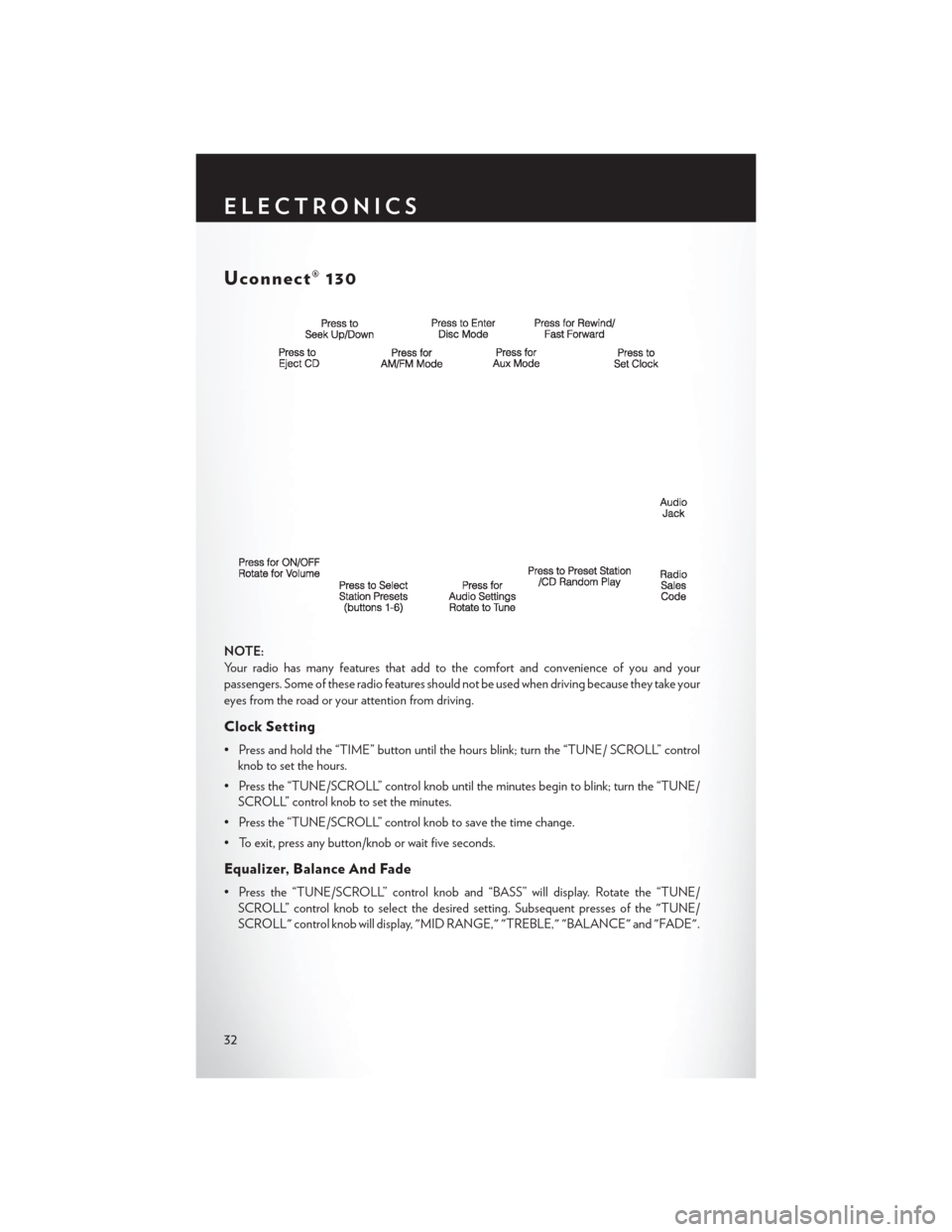
Clock Setting
• Press and hold the “TIME” button until the hours blink; turn the “TUNE/ SCROLL” controlknob to set the hours.
• Press the “TUNE/SCROLL” control knob until the minutes begin to blink; turn the “TUNE/ SCROLL” control knob to set the minutes.
• Press the “TUNE/SCROLL” control knob to save the time change.
• To exit, press any button/knob or wait five seconds.
Equalizer, Balance And Fade
• Press the “TUNE/SCROLL” control knob and “BASS” will display. Rotate the “TUNE/ SCROLL” control knob to select the desired setting. Subsequent presses of the "TUNE/
SCROLL" control knob will display, "MID RANGE," "TREBLE," "BALANCE" and "FADE".
ELECTRONICS
32
Page 36 of 124
Uconnect® 130 WITH SiriusXM SATELLITE RADIO
NOTE:
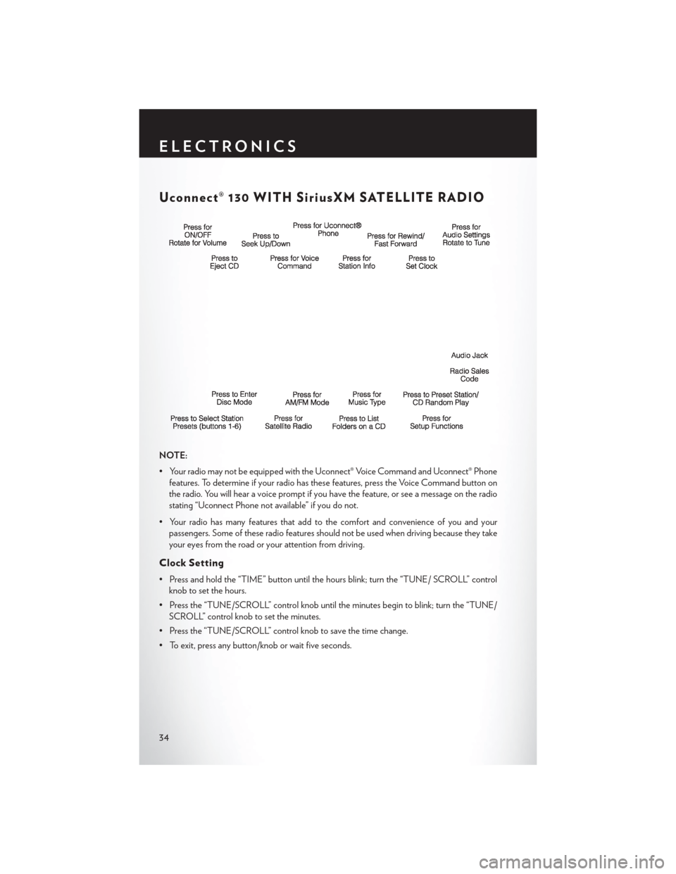
• Your radio may not be equipped with the Uconnect® Voice Command and Uconnect® Phonefeatures. To determine if your radio has these features, press the Voice Command button on
the radio. You will hear a voice prompt if you have the feature, or see a message on the radio
stating “Uconnect Phone not available” if you do not.
• Your radio has many features that add to the comfort and convenience of you and your passengers. Some of these radio features should not be used when driving because they take
your eyes from the road or your attention from driving.
Clock Setting
• Press and hold the “TIME” button until the hours blink; turn the “TUNE/ SCROLL” controlknob to set the hours.
• Press the “TUNE/SCROLL” control knob until the minutes begin to blink; turn the “TUNE/ SCROLL” control knob to set the minutes.
• Press the “TUNE/SCROLL” control knob to save the time change.
• To exit, press any button/knob or wait five seconds.
ELECTRONICS
34
Page 39 of 124
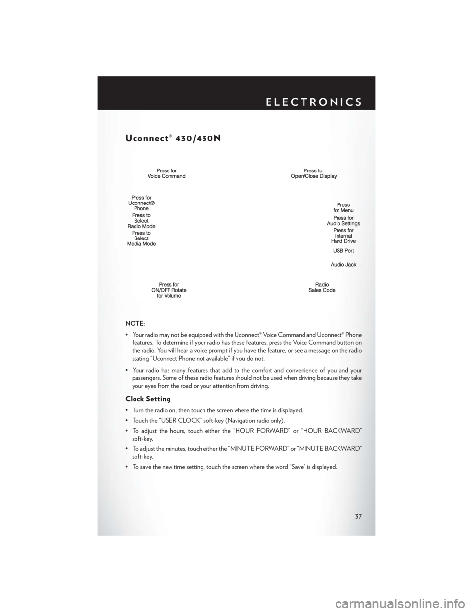
Uconnect® 430/430N
NOTE:
• Your radio may not be equipped with the Uconnect® Voice Command and Uconnect® Phonefeatures. To determine if your radio has these features, press the Voice Command button on
the radio. You will hear a voice prompt if you have the feature, or see a message on the radio
stating “Uconnect Phone not available” if you do not.
• Your radio has many features that add to the comfort and convenience of you and your passengers. Some of these radio features should not be used when driving because they take
your eyes from the road or your attention from driving.
Clock Setting
• Turn the radio on, then touch the screen where the time is displayed.
• Touch the “USER CLOCK” soft-key (Navigation radio only).
• To adjust the hours, touch either the “HOUR FORWARD” or “HOUR BACKWARD”soft-key.
• To adjust the minutes, touch either the “MINUTE FORWARD” or “MINUTE BACKWARD” soft-key.
• To save the new time setting, touch the screen where the word “Save” is displayed.
ELECTRONICS
37
Page 49 of 124
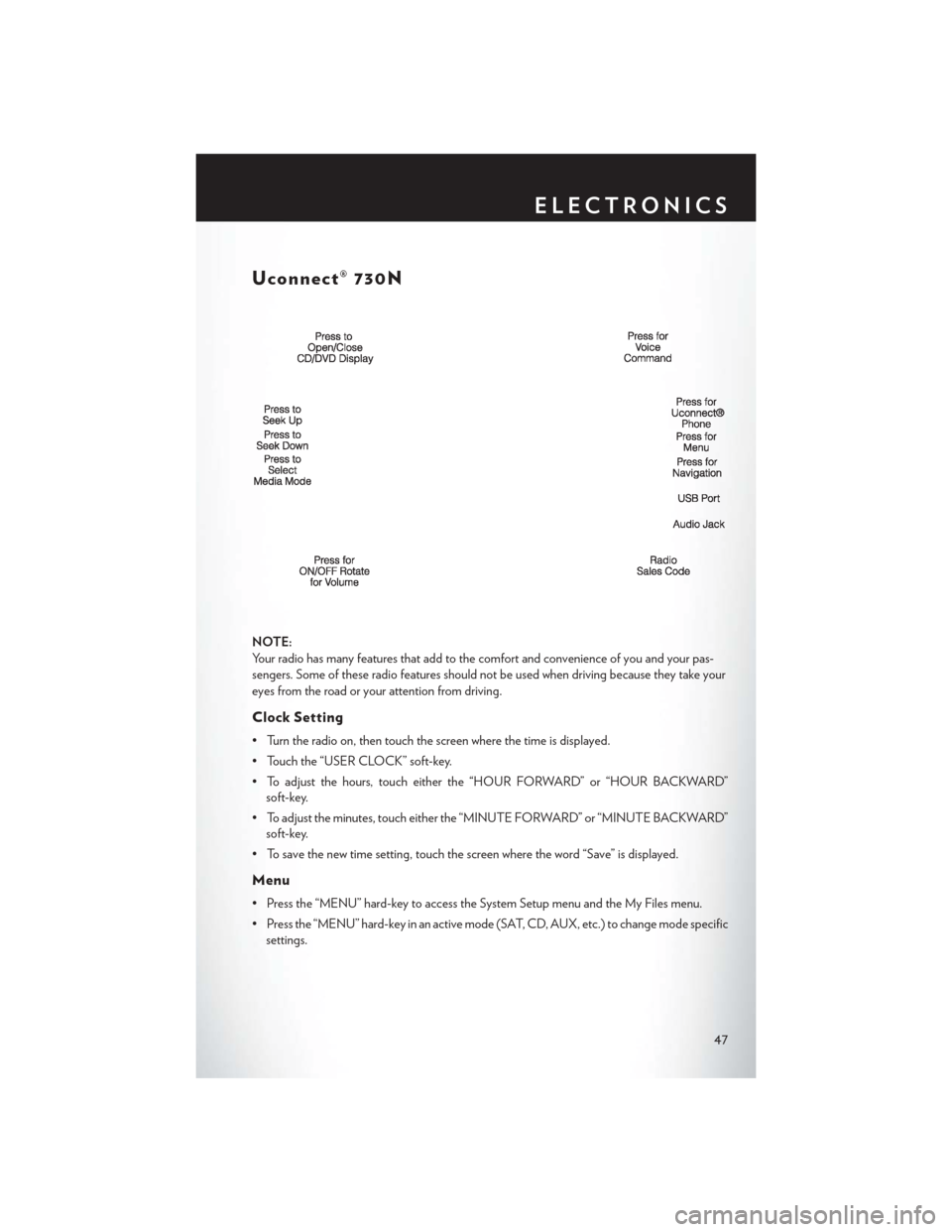
Uconnect® 730N
NOTE:
Your radio has many features that add to the comfort and convenience of you and your pas-
sengers. Some of these radio features should not be used when driving because they take your
eyes from the road or your attention from driving.
Clock Setting
• Turn the radio on, then touch the screen where the time is displayed.
• Touch the “USER CLOCK” soft-key.
• To adjust the hours, touch either the “HOUR FORWARD” or “HOUR BACKWARD”soft-key.
• To adjust the minutes, touch either the “MINUTE FORWARD” or “MINUTE BACKWARD” soft-key.
• To save the new time setting, touch the screen where the word “Save” is displayed.
Menu
• Press the “MENU” hard-key to access the System Setup menu and the My Files menu.
• Press the “MENU” hard-key in an active mode (SAT, CD, AUX, etc.) to change mode specific settings.
ELECTRONICS
47
Page 64 of 124
SETTING THE ANALOG CLOCK
To set the analog clock at the top center of the instrument panel, press and hold the button until
the setting is correct.
iPod®/USB/MP3 CONTROL
• There are many ways to play music from iPod®/MP3 players or USB devices through yourvehicle's sound system.
• The remote USB port, located within the front storage area, allows you to plug an iPod® into the vehicle's sound system.
NOTE:
If equipped with the Uconnect® 730N, the USB
port on the faceplate allows the same functions
as the remote USB port.
• Non-Touch-Screen Radios: To hear audio
from devices connected to the USB port,
press the “AUX” button on the radio face-
plate.
Setting The Analog Clock
ELECTRONICS
62
Page 87 of 124
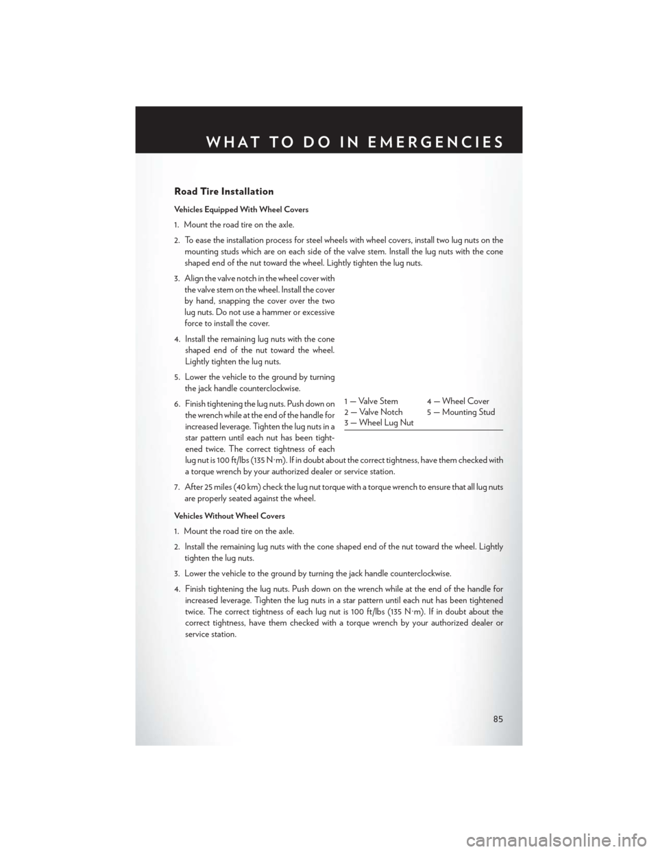
Road Tire Installation
Vehicles Equipped With Wheel Covers
1. Mount the road tire on the axle.
2. To ease the installation process for steel wheels with wheel covers, install two lug nuts on themounting studs which are on each side of the valve stem. Install the lug nuts with the cone
shaped end of the nut toward the wheel. Lightly tighten the lug nuts.
3. Align the valve notch in the wheel cover with the valve stem on the wheel. Install the cover
by hand, snapping the cover over the two
lug nuts. Do not use a hammer or excessive
force to install the cover.
4. Install the remaining lug nuts with the cone shaped end of the nut toward the wheel.
Lightly tighten the lug nuts.
5. Lower the vehicle to the ground by turning the jack handle counterclockwise.
6. Finish tightening the lug nuts. Push down on the wrench while at the end of the handle for
increased leverage. Tighten the lug nuts in a
star pattern until each nut has been tight-
ened twice. The correct tightness of each
lug nut is 100 ft/lbs (135 N·m). If in doubt about the correct tightness, have them checked with
a torque wrench by your authorized dealer or service station.
7. After 25 miles (40 km) check the lug nut torque with a torque wrench to ensure that all lug nuts are properly seated against the wheel.
Vehicles Without Wheel Covers
1. Mount the road tire on the axle.
2. Install the remaining lug nuts with the cone shaped end of the nut toward the wheel. Lightly tighten the lug nuts.
3. Lower the vehicle to the ground by turning the jack handle counterclockwise.
4. Finish tightening the lug nuts. Push down on the wrench while at the end of the handle for increased leverage. Tighten the lug nuts in a star pattern until each nut has been tightened
twice. The correct tightness of each lug nut is 100 ft/lbs (135 N·m). If in doubt about the
correct tightness, have them checked with a torque wrench by your authorized dealer or
service station.
1 — Valve Stem 4 — Wheel Cover
2 — Valve Notch 5 — Mounting Stud
3 — Wheel Lug Nut
WHAT TO DO IN EMERGENCIES
85
Page 105 of 124
FUSES
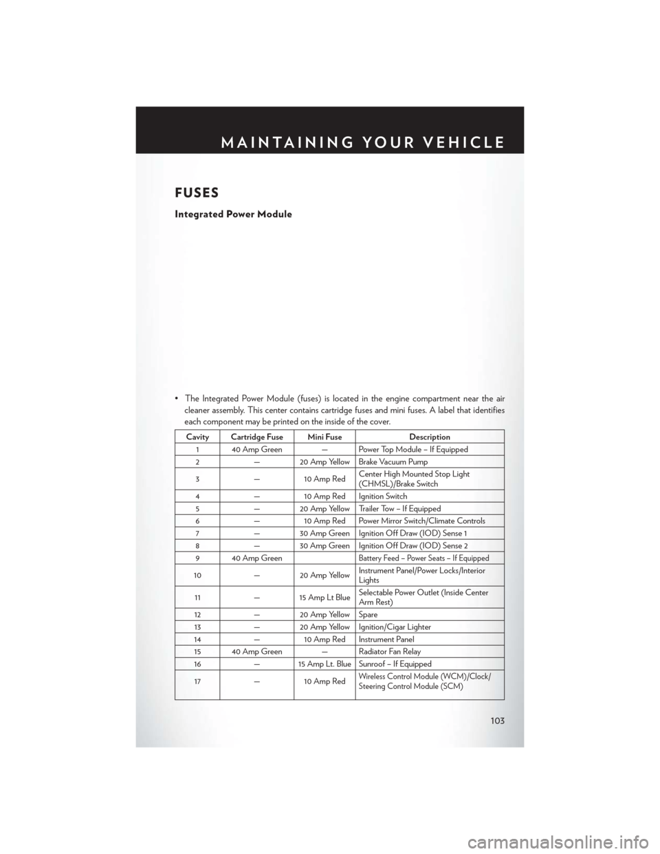
Integrated Power Module
• The Integrated Power Module (fuses) is located in the engine compartment near the aircleaner assembly. This center contains cartridge fuses and mini fuses. A label that identifies
each component may be printed on the inside of the cover.
Cavity Cartridge Fuse Mini Fuse Description
1 40 Amp Green — Power Top Module – If Equipped
2 — 20 Amp Yellow Brake Vacuum Pump
3 —10 Amp Red Center High Mounted Stop Light
(CHMSL)/Brake Switch
4 —10 Amp Red Ignition Switch
5 — 20 Amp Yellow Trailer Tow – If Equipped
6 —10 Amp Red Power Mirror Switch/Climate Controls
7 — 30 Amp Green Ignition Off Draw (IOD) Sense 1
8 — 30 Amp Green Ignition Off Draw (IOD) Sense 2
9 40 Amp Green
Battery Feed – Power Seats – If Equipped
10 — 20 Amp Yellow Instrument Panel/Power Locks/Interior
Lights
11 — 15 Amp Lt Blue Selectable Power Outlet (Inside Center
Arm Rest)
12 — 20 Amp Yellow Spare
13 — 20 Amp Yellow Ignition/Cigar Lighter
14 —10 Amp Red Instrument Panel
15 40 Amp Green — Radiator Fan Relay
16 — 15 Amp Lt. Blue Sunroof – If Equipped
17 —10 Amp Red
Wireless Control Module (WCM)/Clock/
Steering Control Module (SCM)
MAINTAINING YOUR VEHICLE
103
Page 112 of 124
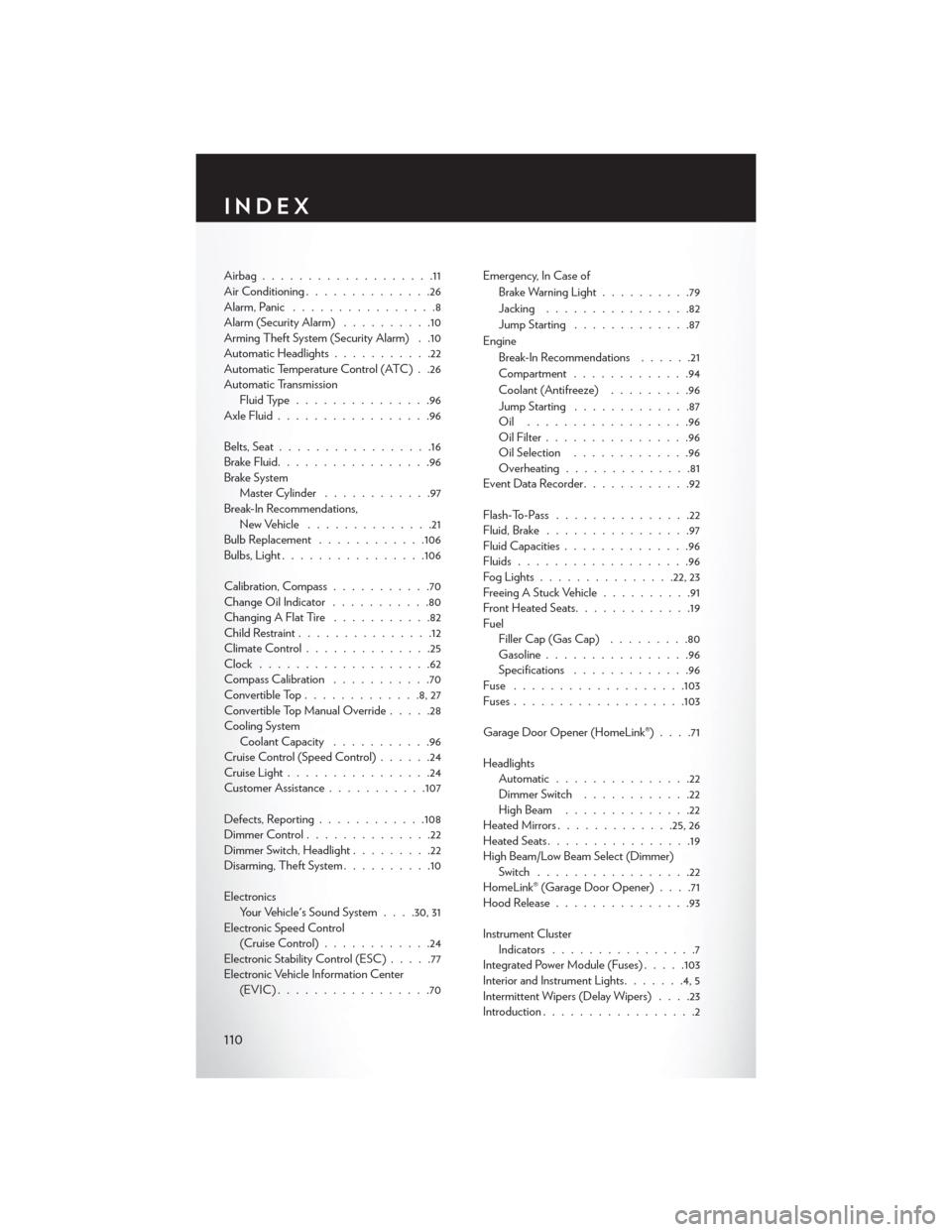
Airbag...................11
Air Conditioning..............26
Alarm, Panic ................8
Alarm (Security Alarm) ..........10
Arming Theft System (Security Alarm) . .10
Automatic Headlights ...........22
Automatic Temperature Control (ATC) . .26
Automatic Transmission Fluid Type ...............96
Axle Fluid .................96
Belts, Seat .................16
Brake Fluid .................96
Brake System Master Cylinder ............97
Break-In Recommendations, New Vehicle ..............21
Bulb Replacement ............106
Bulbs,Light............... .106
Calibration, Compass ...........70
Change Oil Indicator ...........80
Changing A Flat Tire ...........82
Child Restraint ...............12
Climate Control ..............25
Clock ...................62
Compass Calibration ...........70
Convertible Top .............8,27
Convertible Top Manual Override .....28
Cooling System Coolant Capacity ...........96
Cruise Control (Speed Control) ......24
Cruise Light ................24
Customer Assistance ...........107
Defects, Reporting ............108
Dimmer Control ..............22
Dimmer Switch, Headlight .........22
Disarming, Theft System ..........10
Electronics Your Vehicle's Sound System . . . .30, 31
Electronic Speed Control (Cruise Control) ............24
Electronic Stability Control (ESC) .....77
Electronic Vehicle Information Center (EVIC).................70 Emergency, In Case of
Brake Warning Light ..........79
Jacking ................82
Jump Starting .............87
Engine Break-In Recommendations ......21
Compartment .............94
Coolant (Antifreeze) .........96
Jump Starting .............87
Oil ..................96
Oil Filter ................96
Oil Selection .............96
Overheating ..............81
EventDataRecorder............92
Flash-To-Pass ...............22
Fluid, Brake ................
97
Fluid Capacities ..............96
Fluids ...................96
FogLights...............22, 23
Freeing A Stuck Vehicle ..........91
Front Heated Seats .............19
Fuel Filler Cap (Gas Cap) .........80
Gasoline ................96
Specifications .............96
Fuse .................. .103
Fuses ...................103
Garage Door Opener (HomeLink®) ....71
Headlights Automatic ...............22
Dimmer Switch ............22
HighBeam ..............22
Heated Mirrors .............25, 26
Heated Seats ................19
High Beam/Low Beam Select (Dimmer) Switch .................22
HomeLink® (Garage Door Opener) ....71
Hood Release ...............93
Instrument Cluster Indicators ................7
Integrated Power Module (Fuses) .....103
Interior and Instrument Lights .......4,5
Intermittent Wipers (Delay Wipers) ....23
Introduction .................2
INDEX
110