lock CHRYSLER 300 2011 2.G Owner's Manual
[x] Cancel search | Manufacturer: CHRYSLER, Model Year: 2011, Model line: 300, Model: CHRYSLER 300 2011 2.GPages: 92, PDF Size: 3.35 MB
Page 37 of 92
SIRIUS SATELLITE RADIO• SIRIUS® Satellite Radio gives you over 130 channels, including 100% commercial-free musicfrom nearly every genre, plus all your favorite sports, news, talk and entertainment channels –all
with crystal clear, coast-to-coast coverage, all in one place and all at your fingertips.
• To access SIRIUS Satellite Radio, touch the SAT soft-key on the main Radio screen.
• The following describes features that are available when in SIRIUS Satellite Radio mode.
Selecting SIRIUS Satellite Channels
Seek Up/Seek Down
• Touch the Seek arrow soft-keys for less than 2 seconds to seek through channels in SAT mode.
• Touch and hold either arrow soft-key for more than 2 seconds to bypass channels without stopping. The radio will stop at the next listenable channel once the arrow soft-key is released.
Direct Tune • Tune directly to a SAT channel by pressing the “Tune” button on the screen, and entering the desired station number.
Jump
• Automatically tells you when Traffic & Weather for a favorite city is available, and gives you theoption to switch to that channel. Touch Jump to activate the feature. After listening to Traffic
and Weather, touch Jump again to return to the previous channel.
Fav
• Activates the favorites menu. You can add up to 50 favorite artists or songs. Just touch Add FavArtist or Add Fav Song while the song is playing. You will then be alerted any time one of these
songs, or works by these artists, is playing on other SIRIUS channels.
SIRIUS Parental Controls
• You can skip or hide certain channels from view if you do not want access to them. Touch theMore soft-key, then the Settings soft-key, next touch the SIRIUS Setup soft-key, then select
Channel Skip. Touch the box, check-mark, next to the channel you want skipped. They will not
show up in normal usage.
• SIRIUS also offers the option to permanently block selected channels. Call 1-888-539-7474 and request the Family Package. ELECTRONICS
35
Page 51 of 92
Compass Calibration
• This compass is self-calibrating, which eliminates the need to set the compass manually. Whenthe vehicle is new, the compass may appear erratic and the EVIC will display “CAL” until the
compass is calibrated.
• You may also calibrate the compass by completing one or more 360 degree turns (in an area free from large metal or metallic objects) until the “CAL” message displayed in the EVIC turns
off. The compass will now function normally.
ECO
• The ECO message will appear in your EVIC display whenever you are driving in a fuel efficientmanner.
• This feature allows you to monitor when you are driving in a fuel efficient manner, and it can be used to modify driving habits in order to increase fuel economy.
PROGRAMMABLE FEATURES
Electronic Vehicle Information Center (EVIC) – If Equipped
• The EVIC can be used to view or change the following settings. Press the UPor
DOWN
button until System Setup displays, then press the SELECTbutton. Scroll
through the settings using the UP or DOWN buttons. Press the SELECT
button to
change the setting. Press the BACK button to scroll back to a previous menu or sub menu.
• Fuel Economy: • Average Fuel Economy/Fuel Saver Mode
• Distance To Empty (DTE)
• Miles Per Gallon (MPG) • Trip Info
• Trip A
• Trip B
• Elapsed Time
• Vehicle Speed • Units
• To Reset The Display • Vehicle Info (Customer Information Features)
Uconnect Touch™ Customer Programmable Features
• The Uconnect Touch™ 8.4 system allows you to access Customer Programmable feature
settings such as Display, Clock, Safety/Assistance, Lights, Doors & Locks, Heated Seats, Engine
Off Operation, Compass Settings, Audio, Phone/ Bluetooth and SIRIUS Setup through
soft-keys.
• Touch the More soft-key to on the bottom of the screen, then touch the Settings soft-key to access the Settings screen. When making a selection, scroll up or down until the preferred
setting is highlighted, then press and release the preferred setting until a check-mark appears
next to the setting, showing that setting has been selected. The following feature settings are
available:
• Display • Clock
• Safety / Assistance • Doors & Locks
• Auto-On Comfort & Remote Start • Engine Off Options
• Compass Settings • Audio
• Phone / Bluetooth • SIRIUS Setup
ELECTRONICS
49
Page 54 of 92
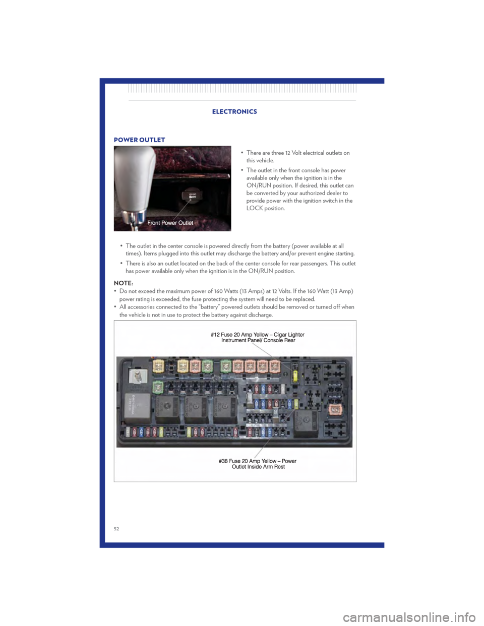
POWER OUTLET• There are three 12 Volt electrical outlets onthis vehicle.
• The outlet in the front console has power available only when the ignition is in the
ON/RUN position. If desired, this outlet can
be converted by your authorized dealer to
provide power with the ignition switch in the
LOCK position.
• The outlet in the center console is powered directly from the battery (power available at all times). Items plugged into this outlet may discharge the battery and/or prevent engine starting.
• There is also an outlet located on the back of the center console for rear passengers. This outlet has power available only when the ignition is in the ON/RUN position.
NOTE:
• Do not exceed the maximum power of 160 Watts (13 Amps) at 12 Volts. If the 160 Watt (13 Amp) power rating is exceeded, the fuse protecting the system will need to be replaced.
• All accessories connected to the “battery” powered outlets should be removed or turned off when the vehicle is not in use to protect the battery against discharge.
ELECTRONICS
52
Page 58 of 92

• Your vehicle has also been equipped with a TPMS malfunction indicator to indicate when thesystem is not operating properly. The TPMS malfunction indicator is combined with the low tire
pressure telltale. When the system detects a malfunction, the telltale will flash for approximately
one minute and then remain continuously illuminated. This sequence will continue each time
the vehicle is restarted as long as the malfunction exists.
• When the malfunction indicator is illuminated, the system may not be able to detect or signal low tire pressure as intended. TPMS malfunctions may occur for a variety of reasons, including
the installation of replacement or alternate tires or wheels on the vehicle that prevent the TPMS
from functioning properly. Always check the TPMS malfunction telltale after replacing one or
more tires or wheels on your vehicle, to ensure that the replacement or alternate tires and
wheels allow the TPMS to continue to function properly.
CAUTION!
The TPMS has been optimized for the original equipment tires and wheels. TPMS
pressures and warning have been established for the tire size equipped on your vehicle.
Undesirable system operation or sensor damage may result when using replacement
equipment that is not of the same size, type, and/or style. Aftermarket wheels can cause
sensor damage. Do not use tire sealant from a can, or balance beads if your vehicle is
equipped with a TPMS, as damage to the sensors may result.
- Engine Temperature Warning Light
• This light warns of an overheated engine condition.
• If the light turns on or flashes continuously while driving, safely pull over and stop the vehicle. Ifthe A/C system is on, turn it off. Also, shift the transmission into NEUTRAL and idle the
vehicle. If the temperature reading does not return to normal, turn the engine off immediately.
• We recommend that you do not operate the vehicle or engine damage will occur. Have the vehicle serviced immediately.
WARNING!
A hot engine cooling system is dangerous. You or others could be badly burned by steam
or boiling coolant. You may want to call an authorized service center for service if your
vehicle overheats.
BRAKE- Brake Warning Light
• The Brake Warning light illuminates when there is either a system malfunction or the parkingbrake is applied. If the light is on and the parking brake is not applied, it indicates a possible
brake hydraulic malfunction, brake booster problem or an Anti-Lock Brake System problem.
• We recommend you drive to the nearest service center and have the vehicle serviced immediately. WHAT TO DO IN EMERGENCIES
56
Page 59 of 92

WARNING!
Driving a vehicle with the red brake light on is dangerous. Part of the brake system may
have failed. It will take longer to stop the vehicle. You could have a collision. Have the
vehicle checked immediately.
- Malfunction Indicator Light (MIL)
• Certain conditions, such as a poor fuel quality, etc., may illuminate the MIL after engine start.The vehicle should be serviced if the light stays on through several typical driving cycles. In
most situations, the vehicle will drive normally and not require towing.
• If the MIL flashes when the engine is running, serious conditions may exist that could lead to immediate loss of power or severe catalytic converter damage. We recommend you do not
operate the vehicle. Have the vehicle serviced immediately.
- Electronic Stability Control (ESC) OFF Indicator Light
• This light indicates the Electronic Stability Control (ESC) is off.
- Charging System Light
• This light shows the status of the electrical charging system. If the charging system lightremains on, it means that the vehicle is experiencing a problem with the charging system.
• We recommend you do not continue driving if the charging system light is on. Have the vehicle serviced immediately.
- Oil Pressure Warning Light
• This light indicates low engine oil pressure. If the light turns on while driving, stop the vehicleand shut off the engine as soon as possible. A chime will sound for four minutes when this light
turns on.
• We recommend you do not operate the vehicle or engine damage will occur. Have the vehicle serviced immediately.
- Anti-Lock Brake (ABS) Light
• This light monitors the Anti-Lock Brake System (ABS).
• If the light is not on during starting, stays on, or turns on while driving, we recommend you driveto the nearest service center and have the vehicle serviced immediately. WHAT TO DO IN EMERGENCIES
57
Page 60 of 92
- Electronic Throttle Control (ETC) Light
• This light informs you of a problem with the Electronic Throttle Control (ETC) system.
• If a problem is detected, the light will come on while the engine is running. Cycle the ignitionwhen the vehicle has completely stopped and the shift lever is placed in the PARK position; the
light should turn off.
• If the light remains lit with the engine running, your vehicle will usually be drivable; however, see an authorized service center immediately. If the light is flashing when the engine is running,
immediate service is required and you may experience reduced performance, an
elevated/rough idle or engine stall and your vehicle may require towing.
- Airbag Warning Light
• If the light is not on during starting, stays on, or turns on while driving, have the vehicle servicedby an authorized service center immediately.
SERVICE AWD SYSTEM Message
• If the SERVICE AWD SYSTEM warning message appears after engine start up, or duringdriving, it means the AWD system is not functioning properly. We recommend you do not
operate the vehicle. Have the vehicle serviced immediately.
Oil Change Indicator
Message
• If an “oil change” message (shown as Oil Change Required) appears and a single chime sounds, it is time for your next required oil change.
Resetting The Light After Servicing
• Without pressing the brake pedal, push the ENGINE START/STOP button and cycle the ignition to the ON/RUN position (Do not start the engine.)
• Fully depress the accelerator pedal three times within 10 seconds.
• Without pressing the brake pedal, push the ENGINE START/STOP button once to return the ignition to the OFF/LOCK position. WHAT TO DO IN EMERGENCIES
58
Page 62 of 92
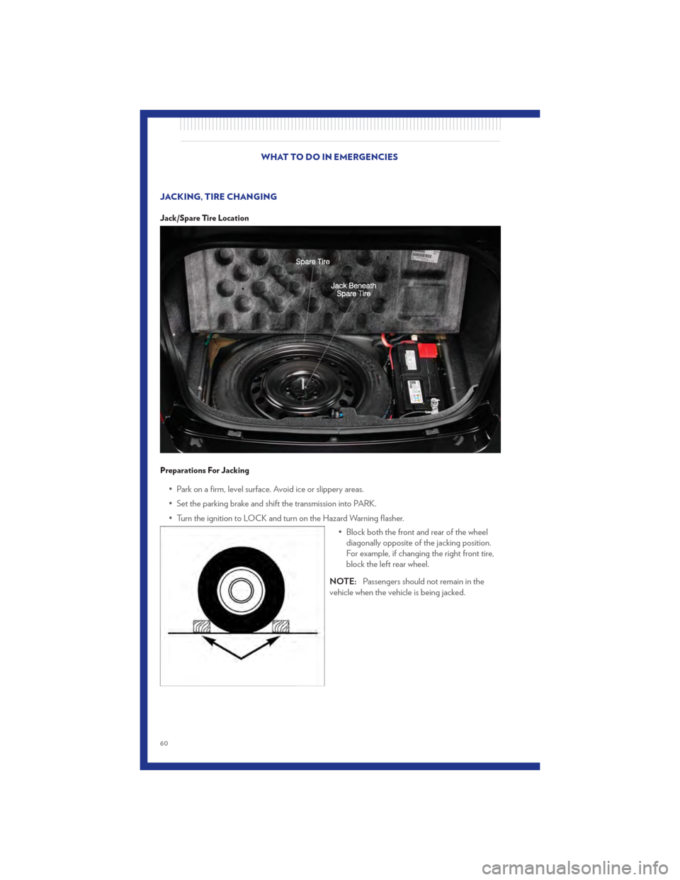
JACKING, TIRE CHANGING
Jack/Spare Tire Location
Preparations For Jacking
• Park on a firm, level surface. Avoid ice or slippery areas.
• Set the parking brake and shift the transmission into PARK.
• Turn the ignition to LOCK and turn on the Hazard Warning flasher.• Block both the front and rear of the wheeldiagonally opposite of the jacking position.
For example, if changing the right front tire,
block the left rear wheel.
NOTE: Passengers should not remain in the
vehicle when the vehicle is being jacked.
WHAT TO DO IN EMERGENCIES
60
Page 63 of 92
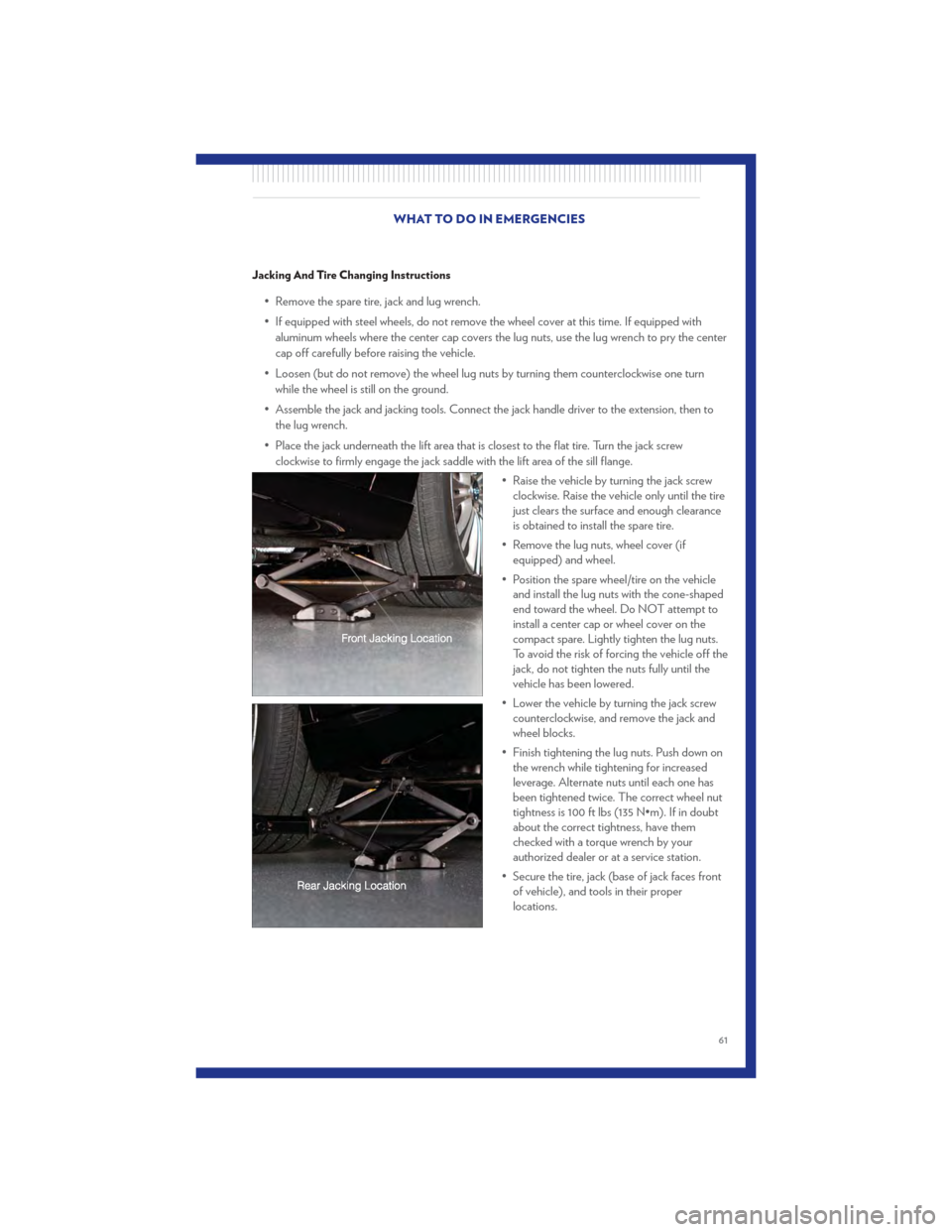
Jacking And Tire Changing Instructions
• Remove the spare tire, jack and lug wrench.
• If equipped with steel wheels, do not remove the wheel cover at this time. If equipped withaluminum wheels where the center cap covers the lug nuts, use the lug wrench to pry the center
cap off carefully before raising the vehicle.
• Loosen (but do not remove) the wheel lug nuts by turning them counterclockwise one turn while the wheel is still on the ground.
• Assemble the jack and jacking tools. Connect the jack handle driver to the extension, then to the lug wrench.
• Place the jack underneath the lift area that is closest to the flat tire. Turn the jack screw clockwise to firmly engage the jack saddle with the lift area of the sill flange.
• Raise the vehicle by turning the jack screwclockwise. Raise the vehicle only until the tire
just clears the surface and enough clearance
is obtained to install the spare tire.
• Remove the lug nuts, wheel cover (if equipped) and wheel.
• Position the spare wheel/tire on the vehicle and install the lug nuts with the cone-shaped
end toward the wheel. Do NOT attempt to
install a center cap or wheel cover on the
compact spare. Lightly tighten the lug nuts.
To avoid the risk of forcing the vehicle off the
jack, do not tighten the nuts fully until the
vehicle has been lowered.
• Lower the vehicle by turning the jack screw counterclockwise, and remove the jack and
wheel blocks.
• Finish tightening the lug nuts. Push down on the wrench while tightening for increased
leverage. Alternate nuts until each one has
been tightened twice. The correct wheel nut
tightness is 100 ft lbs (135 N•m). If in doubt
about the correct tightness, have them
checked with a torque wrench by your
authorized dealer or at a service station.
• Secure the tire, jack (base of jack faces front of vehicle), and tools in their proper
locations.
WHAT TO DO IN EMERGENCIES
61
Page 70 of 92
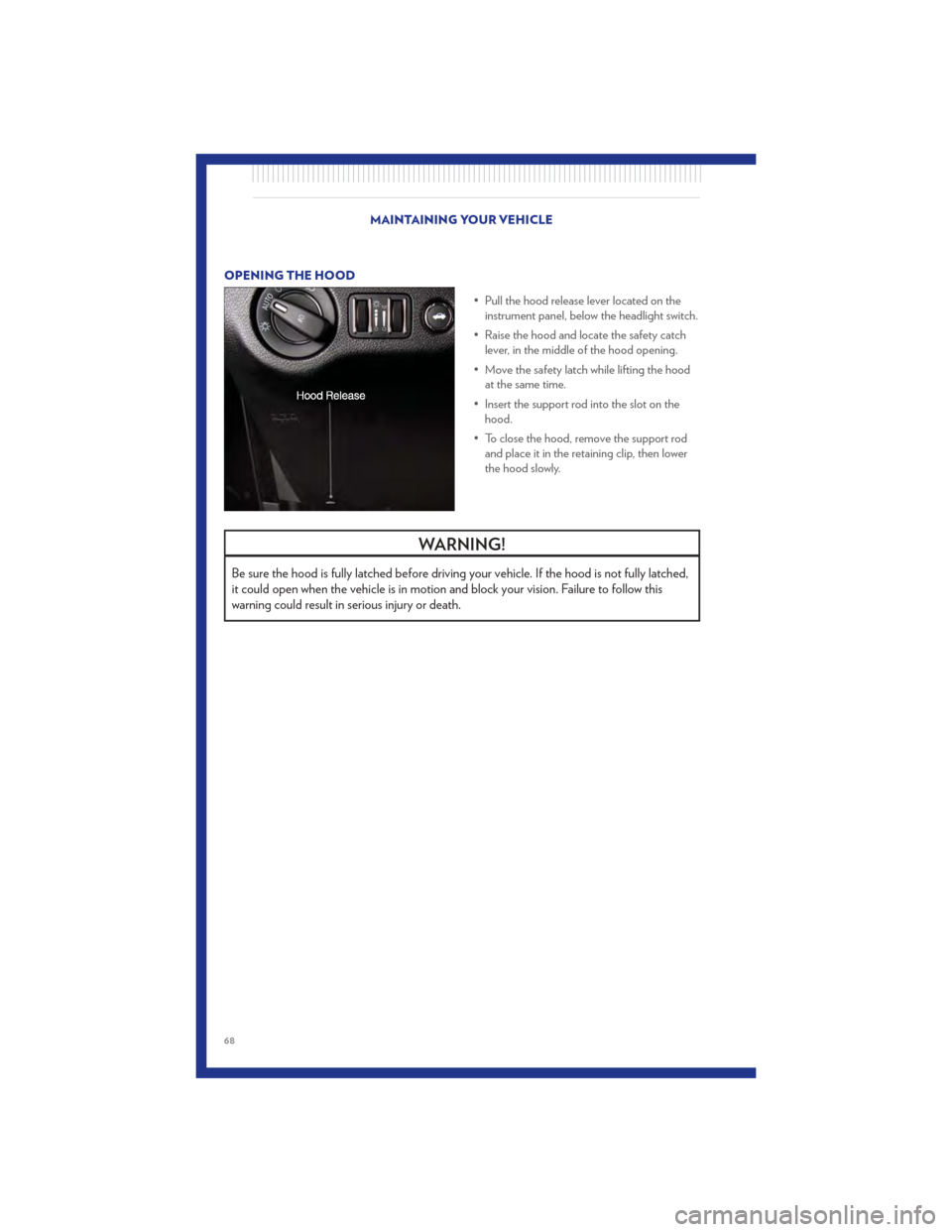
OPENING THE HOOD• Pull the hood release lever located on theinstrument panel, below the headlight switch.
• Raise the hood and locate the safety catch lever, in the middle of the hood opening.
• Move the safety latch while lifting the hood at the same time.
• Insert the support rod into the slot on the hood.
• To close the hood, remove the support rod and place it in the retaining clip, then lower
the hood slowly.
WARNING!
Be sure the hood is fully latched before driving your vehicle. If the hood is not fully latched,
it could open when the vehicle is in motion and block your vision. Failure to follow this
warning could result in serious injury or death.
MAINTAINING YOUR VEHICLE
68
Page 78 of 92
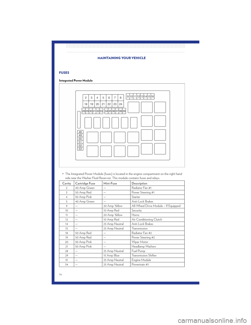
FUSES
Integrated Power Module
• The Integrated Power Module (fuses) is located in the engine compartment on the right handside near the Washer Fluid Reservoir. This module contains fuses and relays.
Cavity Cartridge Fuse Mini-Fuse Description
2 40 Amp Green — Radiator Fan #13 50 Amp Red — Power Steering #1
4 30 Amp Pink — Starter 5 40 Amp Green — Anti-Lock Brakes
9 — 20 Amp Yellow All-Wheel Drive Module – If Equipped
10 — 10 Amp Red Security 11 — 20 Amp Yellow Horns
12 — 10 Amp Red Air Conditioning Clutch
14 — 25 Amp Neutral Anti-Lock Brakes 15 — 25 Amp Neutral Transmission
18 50 Amp Red — Radiator Fan #2 19 50 Amp Red — Power Steering #2
20 30 Amp Pink — Wiper Motor
21 30 Amp Pink — Headlamp Washers
28 — 25 Amp Neutral Fuel Pump
29 — 15 Amp Blue Transmission Shifter
31 — 25 Amp Neutral Engine Module
34 — 25 Amp Neutral Powertrain #1
MAINTAINING YOUR VEHICLE
76