instrument panel CHRYSLER 300 2015 2.G User Guide
[x] Cancel search | Manufacturer: CHRYSLER, Model Year: 2015, Model line: 300, Model: CHRYSLER 300 2015 2.GPages: 180, PDF Size: 30.54 MB
Page 10 of 180
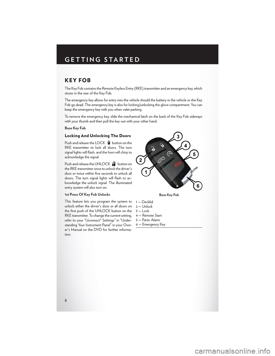
KEY FOB
The Key Fob contains the Remote Keyless Entry (RKE) transmitter and an emergency key, which
stores in the rear of the Key Fob.
The emergency key allows for entry into the vehicle should the battery in the vehicle or the Key
Fob go dead. The emergency key is also for locking /unlocking the glove compartment. You can
keep the emergency key with you when valet parking.
To r e m o v e t h e e m e r g e n c y k e y , s l i d e t h e m e c h a n i c a l l a t c h o n t h e b a c k o f t h e K e y F o b s i d e w a y s
with your thumb and then pull the key out with your other hand.
Base Key Fob
Locking And Unlocking The Doors
Push and release the LOCKbutton on the
RKE transmitter to lock all doors. The turn
signal lights will flash, and the horn will chirp to
acknowledge the signal.
Push and release the UNLOCKbutton on
the RKE transmitter once to unlock the driver's
door or twice within five seconds to unlock all
doors. The turn signal lights will flash to ac-
knowledge the unlock signal. The illuminated
entry system will also turn on.
1st Press Of Key Fob Unlocks
This feature lets you program the system to
unlock either the driver's door or all doors on
the first push of the UNLOCK button on the
RKE transmitter. To change the current setting,
refer to your “Uconnect® Settings” in “Under-
standing Your Instrument Panel” in your Own-
er's Manual on the DVD for further informa-
tion.
Base Key Fob
1 — Decklid2 — Unlock3 — Lock4 — Remote Start5 — Panic Alarm6 — Emergency Key
GETTING STARTED
8
Page 17 of 180
WARNING!
•Inacollision,youandyourpassengerscansuffermuchgreaterinjuriesifyouarenot
properly buckled up. You can strike the interior of your vehicle or other passengers, or you
can be thrown out of the vehicle. Always be sure you and others in your vehicle are buckled
up properly.
•Ashoulderbeltplacedbehindyouwillnotprotectyoufrominjuryduringacollision.You
are more likely to hit your head in a collision if you do not wear your shoulder belt. The lap
and shoulder belt are meant to be used together.
•Aseatbeltthatistooloosewillnotprotectyouproperly.Inasuddenstop,youcouldmove
too far forward, increasing the possibility of injury. Wear your seat belt snugly.
•Afrayedortornseatbeltcouldripapartinacollisionandleaveyouwithnoprotection.
Inspect the seat belt system periodically, checking for cuts, frays, or loose parts. Damaged
parts must be replaced immediately. Do not disassemble or modify the system. Seat belt
assemblies must be replaced after a collision.
SUPPLEMENTAL RESTRAINT SYSTEM (SRS) —
AIR BAGS
Air Bag System Components
Yo u r v e h i c l e m a y b e e q u i p p e d w i t h t h e f o l l o w i n g a i r b a g s y s t e m c o m p o n e n t s :
•OccupantRestraintController(ORC)
• Air Bag Warning Light
• Steering Wheel and Column
• Instrument Panel
•KneeImpactBolsters
• Advanced Front Air Bags
• Supplemental Side Air Bags
• Supplemental Knee Air Bags
•FrontandSideImpactSensors
• Seat Belt Pretentioners
• Seat Belt Buckle Switch
• Seat Track Position Sensors
Advanced Front Air Bags
•ThisvehiclehasAdvancedFrontAirBagsforboththedriverandfrontpassengerasasupplement to the seat belt restraint systems. The Advanced Front Air Bags will not deploy inevery type of collision.
•AdvancedFrontAirBagsaredesignedtoprovideadditionalprotectionbysupplementingtheseat belts. Advanced Front Air Bags are not expected to reduce the risk of injury in rear, side,or rollover collisions.
GETTING STARTED
15
Page 18 of 180
•TheAdvancedFrontAirBagswillnotdeployinallfrontalcollisions,includingsomethatmayproduce substantial vehicle damage — for example, some pole collisions, truck underrides, andangle offset collisions.
•Ontheotherhand,dependingonthetypeandlocationofimpact,AdvancedFrontAirBagsmay deploy in crashes with little vehicle front-end damage but that produce a severe initialdeceleration.
•Becauseairbagsensorsmeasurevehicledecelerationovertime,vehiclespeedanddamagebythemselves are not good indicators of whether or not an air bag should have deployed.
•Seatbeltsarenecessaryforyourprotectioninallcollisions,andalsoareneededtohelpkeep
you in position, away from an inflating air bag.
•Theairbagsmustbereadytoinflateforyourprotectioninacollision.TheOccupantRestraintController (ORC) monitors the internal circuits and interconnecting wiring associated with airbag system electrical components.
•TheORCturnsontheAirBagWarningLightintheinstrumentpanelforapproximatelyfourto eight seconds for a self-check when the ignition switch is first turned to the ON/RUNposition. After the self-check, the Air Bag Warning Light will turn off. If the ORC detects amalfunction in any part of the system, it turns on the Air Bag Warning Light, either momen-tarily or continuously. A single chime will sound to alert you if the light comes on again afterinitial startup.
•TheORCmonitorsthereadinessoftheelectronicpartsoftheairbagsystemwhenevertheignition switch is in the START or ON/RUN position. If the ignition switch is in the OFFposition or in the ACC position, the air bag system is not on and the air bags will not inflate.
•IftheAirBagWarningLightintheinstrumentpanelisnotonduringthefourtoeightsecondswhen the ignition switch is first turned to the ON/RUN position, stays on, or turns on whiledriving, have the vehicle serviced by an authorized service center immediately.
NOTE:
If the speedometer, tachometer, or any engine related gauges are not working, the Occupant
Restraint Controller (ORC ) may also be disabled. In this condition the air bags may not be ready
to inflate for your protection. Have an authorized dealer service the air bag system immediately.
•Afteranycollision,thevehicleshouldbetakentoanauthorizeddealerimmediately.
•Donotdriveyourvehicleaftertheairbagshave deployed. If you are involved in anothercollision, the air bags will not be in place to protect you.
•Ifitisnecessarytomodifytheairbagsystemforpersonswithdisabilities,contactyourauthorized dealer.
•Referto“SupplementalRestraintSystem(SRS)”in“ThingsToKnowBeforeStartingYour
Ve h i c l e ” i n t h e O w n e r ' s M a n u a l o n t h e D V D f o r f u r t h e r i n f o r m a t i o n .
GETTING STARTED
16
Page 19 of 180

Supplemental Knee Air Bags
This vehicle is equipped with a Supplemental Driver Knee Air Bag mounted in the instrument
panel below the steering column. The Supplemental Driver Knee Air Bag provides enhanced
protection during a frontal impact by working together with the seat belts, pretensioners, and
Advanced Front Air Bags.
WARNING!
•Relyingontheairbagsalonecouldleadtomoresevereinjuriesinacollision.Theairbags
work with your seat belt to restrain you properly. In some collisions, the air bags won't
deploy at all. Always wear your seat beltseven though you have air bags.
•BeingtooclosetothesteeringwheelorinstrumentpanelduringAdvancedFrontAirBag
deployment could cause serious injury, including death. Air bags need room to inflate. Sit
back, comfortably extending your arms to reach the steering wheel or instrument panel.
•Noobjectsshouldbeplacedoverorneartheairbagontheinstrumentpanelorsteering
wheel because any such objects could cause harm if the vehicle is in a collision severe
enough to cause the air bag to inflate.
Supplemental Side Air Bags
•ThisvehicleisequippedwithSupplementalSeat-MountedSideAirBags(SABs)locatedin
the outboard side of the front seats. The SABs are marked with a SRS AIRBAG or AIRBAG
label sewn into the outboard side of the seats.
•ThisvehicleisequippedwithSupplementalSideAirBagInflatableCurtains(SABICs)located
above the side windows. The trim covering the SABICs is labeled SRS AIRBAG or AIRBAG.
The SABICs may help reduce the risk of partial or complete ejection of vehicle occupants
through side windows in certain side impact events.
•TheSABICsandSABs(“SideAirBags”)aredesignedtoactivateincertainsideimpactsand
certain rollover events. The Occupant Restraint Controller (“ORC”) determines whether the
deployment of the Side Air Bags in a particular side impact or rollover event is appropriate,
based on the severity and type of collision. Vehicle damage by itself is not a good indicator of
whether or not Side Air Bags should have deployed.
GETTING STARTED
17
Page 27 of 180
Memory Seat
The memory seat feature allows you to save
two different driver seating positions, driver's
outside mirror, adjustable brake and accelera-
tor pedals, power tilt and telescopic steering
column and radio station preset settings. The
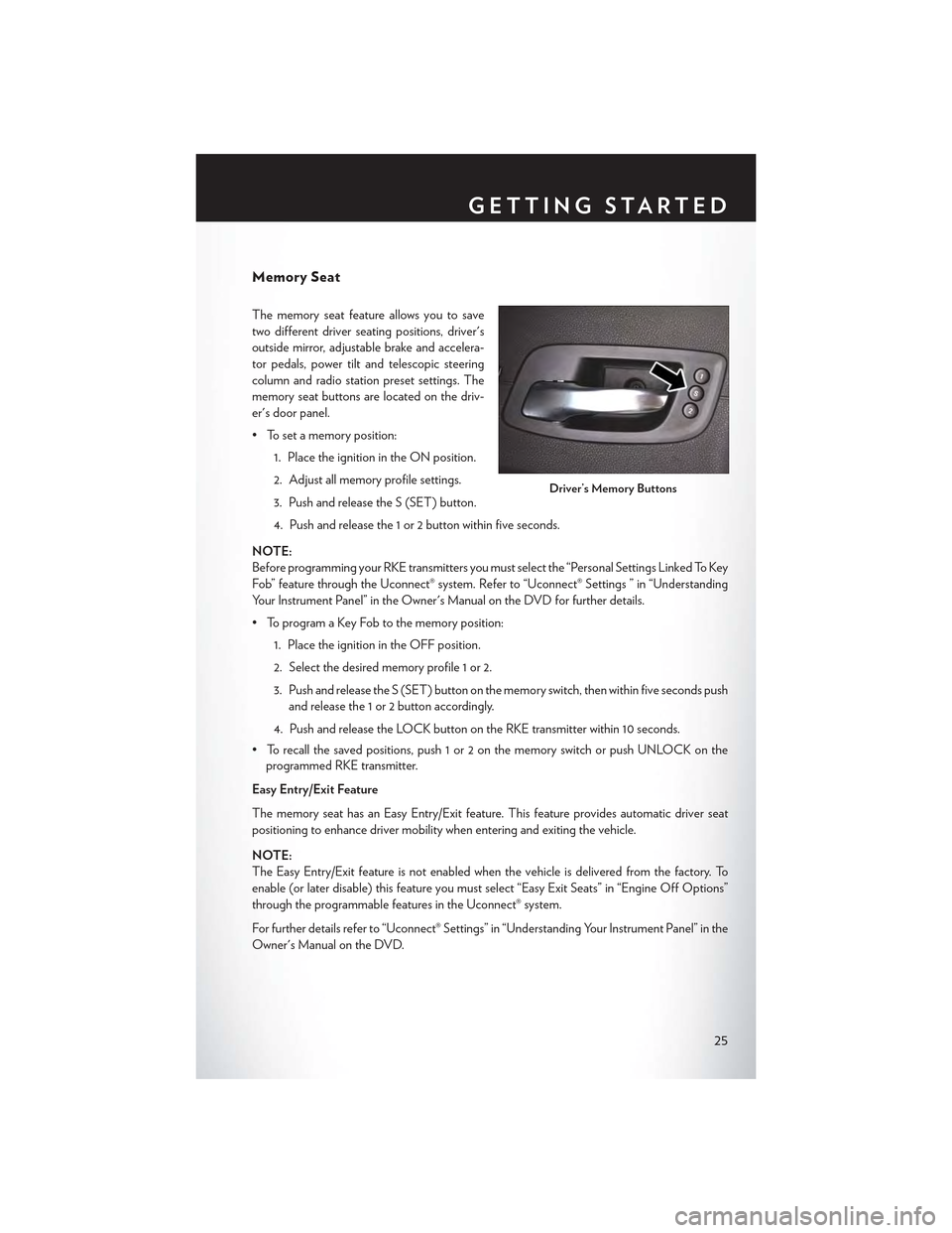
memory seat buttons are located on the driv-
er's door panel.
• To set a memory position:
1. Place the ignition in the ON position.
2. Adjust all memory profile settings.
3. Push and release the S (SET) button.
4. Push and release the 1 or 2 button within five seconds.
NOTE:
Before programming your RKE transmitters you must select the “Personal Settings Linked To Key
Fob” feature through the Uconnect® system. Refer to “Uconnect® Settings ” in “Understanding
Yo u r I n s t r u m e n t P a n e l ” i n t h e O w n e r ' s M a n u a l o n t h e D V D f o r f u r t h e r d e t a i l s .
• To program a Key Fob to the memory position:
1. Place the ignition in the OFF position.
2. Select the desired memory profile 1 or 2.
3. Push and release the S (SET) button on the memory switch, then within five seconds push
and release the 1 or 2 button accordingly.
4. Push and release the LOCK button on the RKE transmitter within 10 seconds.
•Torecallthesavedpositions,push1or2onthememoryswitchorpushUNLOCKonthe
programmed RKE transmitter.
Easy Entry/Exit Feature
The memory seat has an Easy Entry/Exit feature. This feature provides automatic driver seat
positioning to enhance driver mobility when entering and exiting the vehicle.
NOTE:
The Easy Entry/Exit feature is not enabled when the vehicle is delivered from the factory. To
enable (or later disable) this feature you must select “Easy Exit Seats” in “Engine Off Options”
through the programmable features in the Uconnect® system.
For further details refer to “Uconnect® Settings” in “Understanding Your Instrument Panel” in the
Owner's Manual on the DVD.
Driver’s Memory Buttons
GETTING STARTED
25
Page 29 of 180

REAR SEAT
Folding Rear Seatback
•Pullontheloops,locatedneartheoutertopoftheseatbacks,tofolddowneitherorboth
seatbacks. These loops can be tucked away when not in use.
•Whentheseatbackisraisedtotheupright
position, make sure it is latched by strongly
pulling on the top of the seatback above the
seat loop.
WARNING!
•Be certain that the seatback is securely locked into position. If the seatback is not securely locked
into position, the seat will not provide the proper stability for child seats and/or passengers. An
improperly latched seat could cause you and others to severely injured or killed.
•Thecargoareaintherearofthevehicle(withtherearseatbacksinthelocked-upor
folded-down position) should not be used as a play area by children when the vehicle is in
motion. They could be severely injured or killed in a collision. Children should be seated
and using the proper restraint system.
HEATED SEATS
Front Heated Seats
The front heated seats control buttons are located within the climate or controls screen of the
touchscreen.
• Press the heated seat buttononce to turn the HI setting On.
• Press the heated seat buttona second time to turn the LO setting On.
• Press the heated seat buttona third time to turn the heating elements Off.
If the HI-level setting is selected, the system will automatically switch to LO-level after approximately
60 minutes. The LO-level setting will turn Off automatically after approximately 45 minutes.
NOTE:
On models that are equipped with remote start, this feature can be programmed to come on
during a remote start through the Uconnect® system. Refer to “Uconnect® Settings” in “Under-
standing Your Instrument Panel” in the Owner's Manual on the DVD.
Rear Seat Loop
GETTING STARTED
27
Page 35 of 180

Rain Sensing Wipers
This feature senses moisture on the vehicle's windshield and automatically activates the wipers
for the driver when the switch is in the intermittent position. Rotate the end of the lever to one of
four settings to activate this feature and adjust sensitivity.
Rain Sensing can be turned on and off using the Uconnect® System, refer to the Owner's Manual
on the DVD for further details.
High Beam Operation
Push the lever forward to activate the high beams. Pull the lever toward you for flash to pass.
NOTE:
For safe driving, turn off the high beams when oncoming traffic is present to prevent headlight
glare and as a courtesy to other motorists.
HEADLIGHT SWITCH
Automatic Headlights/Parking Lights/Headlights
• Rotate the headlight switch, located on the
instrument panel to the left of the steering
wheel, to the first detent from the off posi-
tion for parking lightand to the sec-
ond detent for headlight.
•Withtheparkinglightsorlowbeamhead-
lights on, push the headlight switch for fog
lights. Pushing the switch a second time will
deactivate the front fog lights. Turning the
headlight switch off will also deactivate the
fog lights.
• Rotate the headlight switch to “AUTO” for
AUTO headlights.
•WhensettoAUTO,thesystemautomati-
cally turns the headlights on or off based on
ambient light levels.
Light Control Switches
1 — Auto2 — Push For Fog Lights3 — Rotate Headlight Switch4 — Rotate Dimmer5 — Rotate Ambient Light Control
OPERATING YOUR VEHICLE
33
Page 36 of 180
Automatic High Beams
The Automatic High Beams system provides increased forward lighting at night by automating
high beam control through the use of a digital camera mounted above the inside rearview mirror.
This camera detects vehicle specific light and automatically switches from high beams to low
beams until the approaching vehicle is out of view. This feature is programmable through the
Uconnect® system. Refer to “Uconnect® Settings” in “Understanding Your Instrument Panel” in
the Owner's Manual on the DVD for further details.
Instrument Panel Dimmer
•Rotatethedimmercontroltotheextremebottompositiontofullydimtheinstrumentpanel
lights and prevent the interior lights from illuminating when a door is opened.
•Rotatethedimmercontroluptoincreasethebrightnessoftheinstrumentpaneland
cupholders when the parking lights or headlights are on.
• Rotate the dimmer control up to the next detent position to fully brighten the odometer and
radio when the parking lights or headlights are on.
• Rotate the dimmer control up to the last detent position to turn on the interior lighting.
•Ifyourvehicleisequippedwithatouchscreen,thedimmingisprogrammablethroughthe
Uconnect® system. Refer to “Uconnect® Settings” in “Understanding Your Instrument Panel”
in the Owner's Manual on the DVD for further details.
Ambient Light Dimmer
• Rotate the ambient light control up or down to increase or decrease the brightness of the
release handle, map pocket (if equipped), overhead and floor lighting when the parking lights
or headlights are on.
• Rotate to extreme bottom position to turn off.
OPERATING YOUR VEHICLE
34
Page 37 of 180
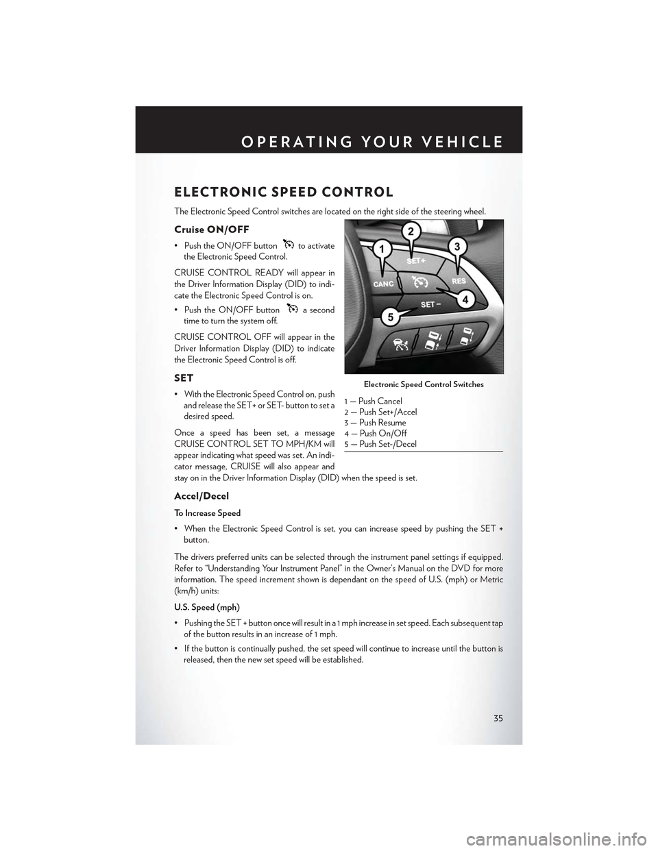
ELECTRONIC SPEED CONTROL
The Electronic Speed Control switches are located on the right side of the steering wheel.
Cruise ON/OFF
• Push the ON/OFF buttonto activate
the Electronic Speed Control.
CRUISE CONTROL READY will appear in
the Driver Information Display (DID) to indi-
cate the Electronic Speed Control is on.
• Push the ON/OFF buttona second
time to turn the system off.
CRUISE CONTROL OFF will appear in the
Driver Information Display (DID) to indicate
the Electronic Speed Control is off.
SET
• With the Electronic Speed Control on, push
and release the SET+ or SET- button to set a
desired speed.
Once a speed has been set, a message
CRUISE CONTROL SET TO MPH/KM will
appear indicating what speed was set. An indi-
cator message, CRUISE will also appear and
stay on in the Driver Information Display (DID) when the speed is set.
Accel/Decel
To Increase Speed
•WhentheElectronicSpeedControlisset,youcanincreasespeedbypushingtheSET+
button.
The drivers preferred units can be selected through the instrument panel settings if equipped.
Refer to “Understanding Your Instrument Panel” in the Owner’s Manual on the DVD for more
information. The speed increment shown is dependant on the speed of U.S. (mph) or Metric
(km/h) units:
U.S. Speed (mph)
• Pushing the SET+button once will result in a 1 mph increase in set speed. Each subsequent tap
of the button results in an increase of 1 mph.
• If the button is continually pushed, the set speed will continue to increase until the button is
released, then the new set speed will be established.
Electronic Speed Control Switches
1 — Push Cancel2—PushSet+/Accel3 — Push Resume4 — Push On/Off5 — Push Set-/Decel
OPERATING YOUR VEHICLE
35
Page 38 of 180

Metric Speed (km/h)
• Pushing the SET+button once will result in a 1 km/h increase in set speed. Each subsequent
tap of the button results in an increase of 1 km/h.
• If the button is continually pushed, the set speed will continue to increase until the button is
released, then the new set speed will be established.
To Decrease Speed
•WhentheElectronicSpeedControlisset,youcandecreasespeedbypushingtheSET-
button.
The drivers preferred units can be selected through the instrument panel settings if equipped.
Refer to “Understanding Your Instrument Panel” in the Owner’s Manual on the DVD for more
information. The speed decrement shown is dependant on the speed of U.S. (mph) or Metric
(km/h) units:
U.S. Speed (mph)
• Pushing the SET-button once will result in a 1 mph decrease in set speed. Each subsequent
tap of the button results in a decrease of 1 mph.
• If the button is continually pushed, the set speed will continue to decrease until the button is
released, then the new set speed will be established.
Metric Speed (km/h)
• Pushing the SET-button once will result in a 1 km/h decrease in set speed. Each subsequent
tap of the button results in a decrease of 1 km/h.
• If the button is continually pushed, the set speed will continue to decrease until the button is
released, then the new set speed will be established.
Resume
• To resume a previously selected set speed in memory, push the RES button and release.
Cancel
• Push the CANCEL button, or apply the brakes to cancel the set speed and maintain the set
speed memory.
•PushtheON/OFFbuttontoturnthesystemoffanderasethesetspeedmemory.
WARNING!
Leaving the Electronic Speed Control system on when not in use is dangerous. You could
accidentally set the system or cause it to go faster than you want. You could lose control and
have an accident. Always leave the system OFF when you are not using it.
OPERATING YOUR VEHICLE
36