instrument panel CHRYSLER 300 2015 2.G Owner's Manual
[x] Cancel search | Manufacturer: CHRYSLER, Model Year: 2015, Model line: 300, Model: CHRYSLER 300 2015 2.GPages: 180, PDF Size: 30.54 MB
Page 39 of 180
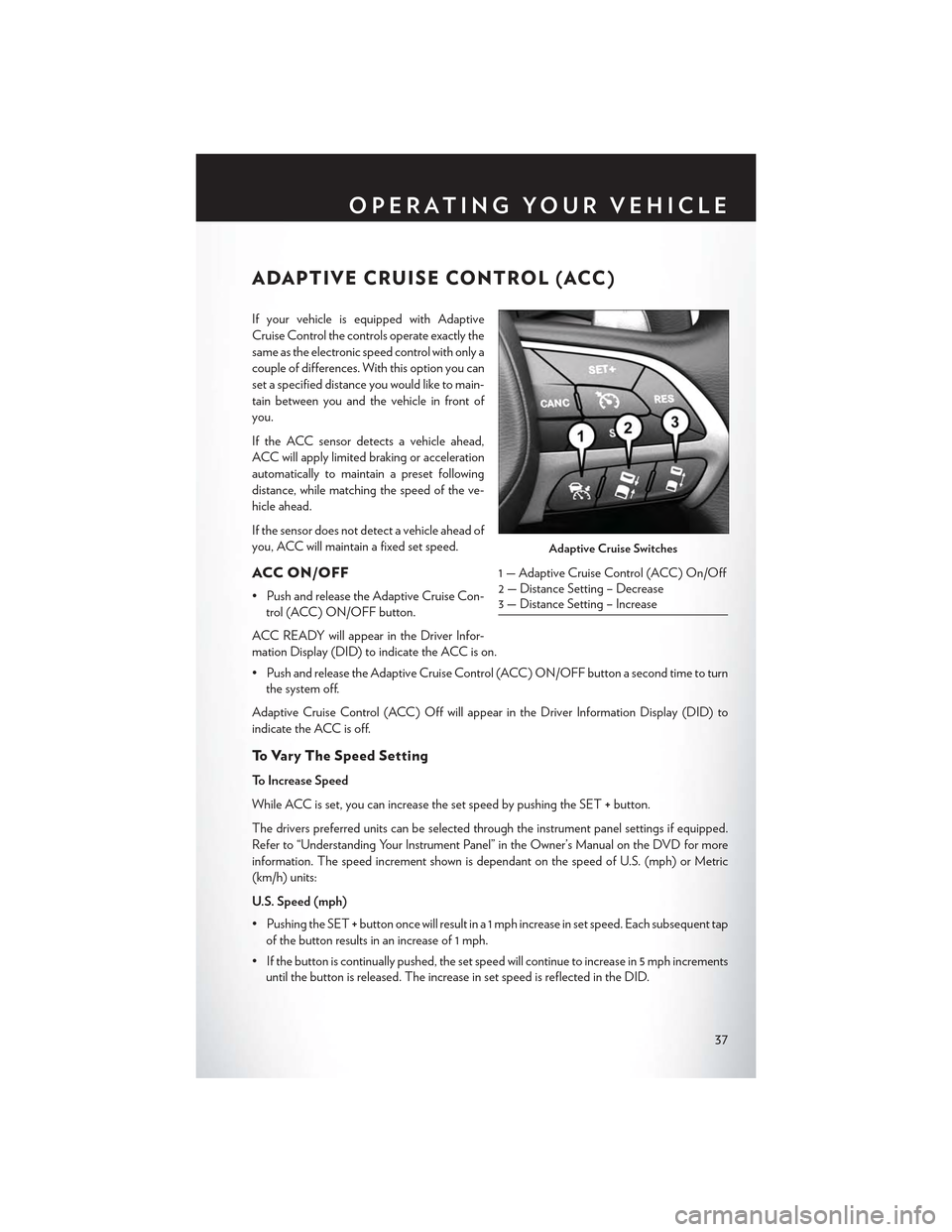
ADAPTIVE CRUISE CONTROL (ACC)
If your vehicle is equipped with Adaptive
Cruise Control the controls operate exactly the
same as the electronic speed control with only a
couple of differences. With this option you can
set a specified distance you would like to main-
tain between you and the vehicle in front of
you.
If the ACC sensor detects a vehicle ahead,
ACC will apply limited braking or acceleration
automatically to maintain a preset following
distance, while matching the speed of the ve-
hicle ahead.
If the sensor does not detect a vehicle ahead of
you, ACC will maintain a fixed set speed.
ACC ON/OFF
•PushandreleasetheAdaptiveCruiseCon-
trol (ACC) ON/OFF button.
ACC READY will appear in the Driver Infor-
mation Display (DID) to indicate the ACC is on.
•PushandreleasetheAdaptiveCruiseControl(ACC)ON/OFFbuttonasecondtimetoturn
the system off.
Adaptive Cruise Control (ACC) Off will appear in the Driver Information Display (DID) to
indicate the ACC is off.
To V a r y T h e S p e e d S e t t i n g
To Increase Speed
While ACC is set, you can increase the set speed by pushing the SET+button.
The drivers preferred units can be selected through the instrument panel settings if equipped.
Refer to “Understanding Your Instrument Panel” in the Owner’s Manual on the DVD for more
information. The speed increment shown is dependant on the speed of U.S. (mph) or Metric
(km/h) units:
U.S. Speed (mph)
• Pushing the SET+button once will result in a 1 mph increase in set speed. Each subsequent tap
of the button results in an increase of 1 mph.
• If the button is continually pushed, the set speed will continue to increase in 5 mph increments
until the button is released. The increase in set speed is reflected in the DID.
Adaptive Cruise Switches
1—AdaptiveCruiseControl(ACC)On/Off2 — Distance Setting – Decrease3 — Distance Setting – Increase
OPERATING YOUR VEHICLE
37
Page 40 of 180

Metric Speed (km/h)
• Pushing the SET+button once will result in a 1 km/h increase in set speed. Each subsequent
tap of the button results in an increase of 1 km/h.
• If the button is continually pushed, the set speed will continue to increase in 10 km/h
increments until the button is released. The increase in set speed is reflected in the DID.
To Decrease Speed
While ACC is set, the set speed can be decreased by pushing the SET-button.
The drivers preferred units can be selected through the instrument panel settings if equipped.
Refer to “Understanding Your Instrument Panel” in the Owner’s Manual on the DVD for more
information. The speed increment shown is dependant on the speed of U.S. (mph) or Metric
(km/h) units:
U.S. Speed (mph)
• Pushing the SET-button once will result in a 1 mph decrease in set speed. Each subsequent
tap of the button results in a decrease of 1 mph.
• If the button is continually pushed, the set speed will continue to decrease in 5 mph
decrements until the button is released. The decrease in set speed is reflected in the DID.
Metric Speed (km/h)
• Pushing the SET-button once will result in a 1 km/h decrease in set speed. Each subsequent
tap of the button results in a decrease of 1 km/h.
• If the button is continually pushed, the set speed will continue to decrease in 10 km/h
decrements until the button is released. The decrease in set speed is reflected in the DID.
NOTE:
•WhenyouoverrideandpushtheSET+button or SET-buttons, the new Set Speed will be the
current speed of the vehicle.
•WhenyouusetheSET-button to decelerate, if the engine’s braking power does not slow the
vehicle sufficiently to reach the set speed, the brake system will automatically slow the vehicle.
•TheACCsystemdeceleratesthevehicletoafullstopwhenfollowingatargetvehicle.Ifan
ACC host vehicle follows a target vehicle to a standstill, after two seconds the driver will either
have to push the RES (resume) button, or apply the accelerator pedal to reengage the ACC
to the existing Set Speed.
•TheACCsystemmaintainssetspeedwhendrivinguphillanddownhill.However,aslight
speed change on moderate hills is normal. In addition, downshifting may occur while climbing
uphill or descending downhill. This is normal operation and necessary to maintain set speed.
When driving up hill and down hill, the ACC system will cancel if the braking temperature
exceeds normal range (overheated).
OPERATING YOUR VEHICLE
38
Page 44 of 180
LANESENSE
The LaneSense system can be enabled and disabled with the LaneSense button, located on the
switch panel below the Uconnect® display.
• Push the LaneSense buttonto turn the system ON (LED turns off ).
The LaneSense system is operational at speeds above 37 mph (60 km/h) and below 112 mph(180 km/h). The LaneSense system uses a forward looking camera to detect lane markings andmeasure vehicle position within the lane boundaries.
When both lane markings are detected and the driver unintentionally drifts out of the lane (noturn signal applied), the LaneSense system provides a haptic warning in the form of torqueapplied to the steering wheel to prompt the driver to remain within the lane boundaries. If thedriver continues to unintentionally drift out of the lane, the LaneSense system provides a visualwarning through the Driver Information Display (DID) to prompt the driver to remain within thelane boundaries.
The driver may manually override the haptic warning by applying torque into the steering wheelat any time.
When only a single lane marking is detected and the driver unintentionally drifts across the lanemarking (no turn signal applied), the LaneSense system provides a visual warning through theDriver Information Display (DID) to prompt the driver to remain within the lane. When only asingle lane marking is detected, a haptic (torque) warning will not be provided.
Refer to your Owner's Manual on the DVD for further details.
NOTE:
When operating conditions have been met, the LaneSense system will monitor if the driver’shands are on the steering wheel and provides an audible warning to the driver when the driver’shands are not detected on the steering wheel. The system will cancel if the driver does not returntheir hands to the wheel.
PA R K V I E W ® R E A R B AC K- U P C A M E R A
Yo u c a n s e e a n o n - s c r e e n i m a g e o f t h e r e a r o f y o u r v e h i c l e w h e n e v e r t h e t r a n s m i s s i o n i s s h i f t e dinto REVERSE. The ParkView® Rear Back-Up Camera image will be displayed on the radiodisplay screen, located on the center stack of the instrument panel.
If the radio display screen appears foggy, clean the camera lens located on the rear of the vehicleabove the rear license plate.
Refer to “ParkView® Rear Back-Up Camera — If Equipped” in “Understanding The Features Of
Yo u r Ve h i c l e ” i n y o u r O w n e r ' s M a n u a l o n t h e D V D f o r f u r t h e r d e t a i l s .
WARNING!
Drivers must be careful when backing up; even when using the ParkView® Rear Back-Up
Camera. Always check carefully behind your vehicle, and be sure to check for pedestrians,
animals, other vehicles, obstructions, or blind spots before backing up. You must continue to
pay attention while backing up. Failure to do so can result in serious injury or death.
OPERATING YOUR VEHICLE
42
Page 46 of 180
Sport Mode — If Equipped
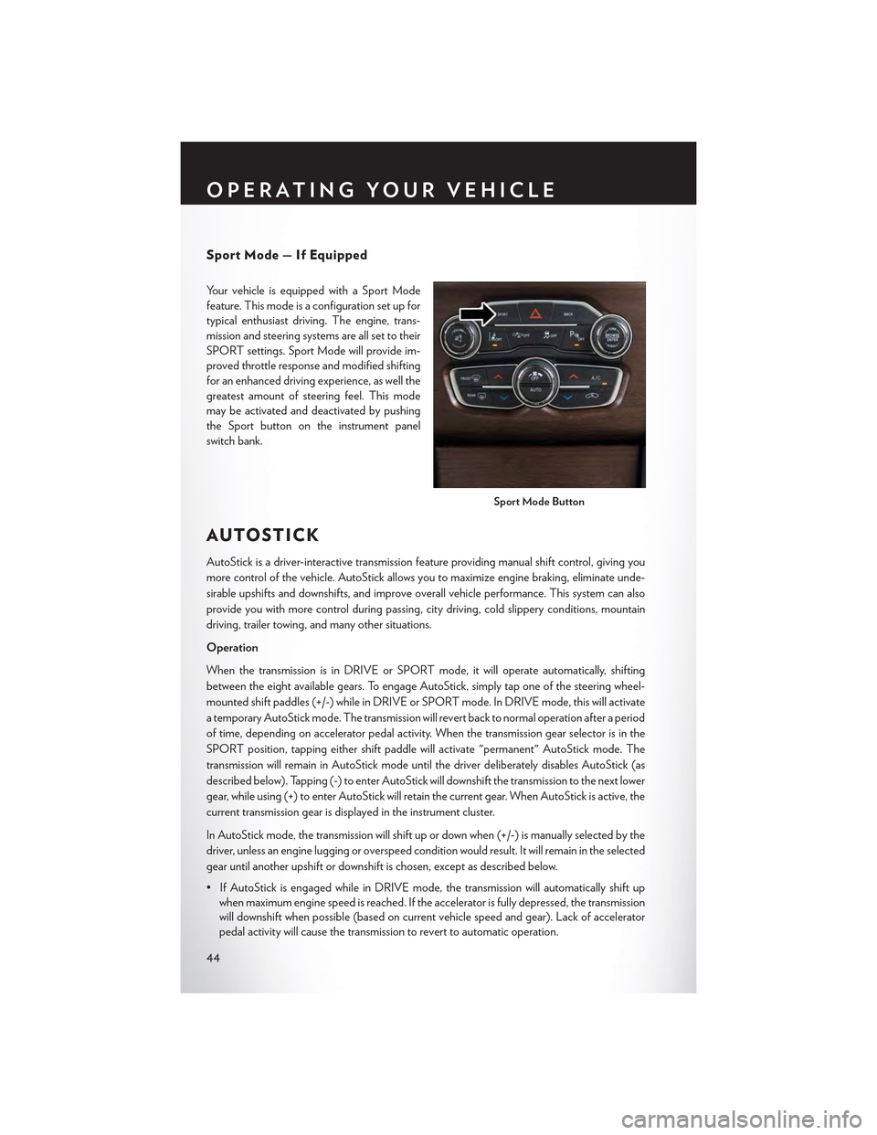
Yo u r v e h i c l e i s e q u i p p e d w i t h a S p o r t M o d e
feature. This mode is a configuration set up for
typical enthusiast driving. The engine, trans-
mission and steering systems are all set to their
SPORT settings. Sport Mode will provide im-
proved throttle response and modified shifting
for an enhanced driving experience, as well the
greatest amount of steering feel. This mode
may be activated and deactivated by pushing
the Sport button on the instrument panel
switch bank.
AUTOSTICK
AutoStick is a driver-interactive transmission feature providing manual shift control, giving you
more control of the vehicle. AutoStick allows you to maximize engine braking, eliminate unde-
sirable upshifts and downshifts, and improve overall vehicle performance. This system can also
provide you with more control during passing, city driving, cold slippery conditions, mountain
driving, trailer towing, and many other situations.
Operation
When the transmission is in DRIVE or SPORT mode, it will operate automatically, shifting
between the eight available gears. To engage AutoStick, simply tap one of the steering wheel-
mounted shift paddles (+/-) while in DRIVE or SPORT mode. In DRIVE mode, this will activate
atemporaryAutoStickmode.Thetransmissionwillrevertbacktonormaloperationafteraperiod
of time, depending on accelerator pedal activity. When the transmission gear selector is in the
SPORT position, tapping either shift paddle will activate "permanent" AutoStick mode. The
transmission will remain in AutoStick mode until the driver deliberately disables AutoStick (as
described below). Tapping (-) to enter AutoStick will downshift the transmission to the next lower
gear, while using (+) to enter AutoStick will retain the current gear. When AutoStick is active, the
current transmission gear is displayed in the instrument cluster.
In AutoStick mode, the transmission will shift up or down when (+/-) is manually selected by the
driver, unless an engine lugging or overspeed condition would result. It will remain in the selected
gear until another upshift or downshift is chosen, except as described below.
• If AutoStick is engaged while in DRIVE mode, the transmission will automatically shift up
when maximum engine speed is reached. If the accelerator is fully depressed, the transmission
will downshift when possible (based on current vehicle speed and gear). Lack of accelerator
pedal activity will cause the transmission to revert to automatic operation.
Sport Mode Button
OPERATING YOUR VEHICLE
44
Page 63 of 180
Selling Your Vehicle
When you sell your vehicle, we recommend that you remove your Uconnect® Access Account
information from the vehicle. You can do this using the radio touchscreen in the vehicle or on the
Mopar Owner Connect website (moparownerconnect.com). Removing your account informa-
tion cancels your subscription and makes your vehicle factory-ready for a new owner/subscriber.
1. From your vehicle’s radio touchscreen, select “Uconnect® Store” from the Apps Menu.
2. Select “My Apps,” then “Settings.” Press “Remove Uconnect® Account.”
3. Enter your Uconnect® Security PIN, and select “Continue.”
For additional information on Uconnect®:
•U.S.residents-visitDriveUconnect.comorcall1-877-855-8400.
•CanadianResidents-visitDriveUconnect.caorcall,1-800-465-2001(English)or
1-800-387-9983 (French).
Built-In Features (Uconnect® 8.4A/8.4AN)
CAUTION!
•Ignoringtherearviewmirrorlightcouldmeanyoumaynothave9-1-1Callserviceif
needed. If the rearview mirror light is illuminated, have an authorized dealer service the
9-1-1 Call system immediately.
•TheOccupantRestraintController(ORC)turnsontheAirBagWarningLightonthe
instrument panel if a malfunction is detected in any part of the air bag system. If the Air
Bag Warning Light is illuminated, the air bag system may not be working properly and the
9-1-1 system may not be able to send a signal to a 9-1-1 operator. If the Air Bag Warning
Light is illuminated, have an authorized dealer service your vehicle immediately.
•Ifanyoneinthevehiclecouldbeindanger(e.g.,fireorsmokeisvisible,dangerousroad
conditions or location), do not wait for voice contact from a 9-1-1 operator. All occupants
should exit the vehicle immediately and move to a safe location.
•Donotaddanyaftermarketelectricalequipmenttothevehicle’selectricalsystem.This
may prevent your vehicle from sending a signal to initiate an emergency call. To avoid
interference that can cause the 9-1-1 Call system to fail, never add aftermarket equipment
(e.g., two-way mobile radio, CB radio, data recorder, etc.) to your vehicle’s electrical
system or modify the antennas on your vehicle. IF YOUR VEHICLE LOSES BATTERY
POWER FOR ANY REASON (INCLUDING DURING OR AFTER AN ACCI-
DENT), THE UCONNECT® FEATURES, APPS AND SERVICES, AMONG OTH-
ERS, WILL NOT OPERATE.
ELECTRONICS
61
Page 120 of 180
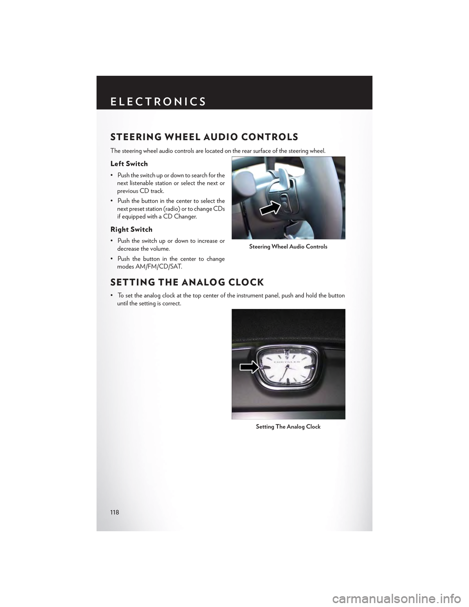
STEERING WHEEL AUDIO CONTROLS
The steering wheel audio controls are located on the rear surface of the steering wheel.
Left Switch
• Push the switch up or down to search for the
next listenable station or select the next or
previous CD track.
• Push the button in the center to select the
next preset station (radio) or to change CDs
if equipped with a CD Changer.
Right Switch
• Push the switch up or down to increase or
decrease the volume.
• Push the button in the center to change
modes AM/FM/CD/SAT.
SETTING THE ANALOG CLOCK
•Tosettheanalogclockatthetopcenteroftheinstrumentpanel,pushandholdthebutton
until the setting is correct.
Steering Wheel Audio Controls
Setting The Analog Clock
ELECTRONICS
118
Page 147 of 180

OPENING THE HOOD
1. Pull the hood release lever located on the
instrument panel, below the headlight
switch.
2. Raise the hood and locate the safety catch
lever, in the middle of the hood opening.
3. Push the safety catch lever to the left while
lifting the hood at the same time.
WARNING!
Be sure the hood is fully latched before driving your vehicle. If the hood is not fully latched, it
could open when the vehicle is in motion and block your vision. Failure to follow this warning
could result in serious injury or death.
Hood Release
MAINTAINING YOUR VEHICLE
145
Page 154 of 180
MAINTENANCE PROCEDURES
For information on the maintenance procedures for your vehicle, please refer to “Maintenance
Procedures” in “Maintaining Your Vehicle” in your Owner’s Manual or applicable supplement on
the DVD for further details.
MAINTENANCE SCHEDULE
Yo u r v e h i c l e i s e q u i p p e d w i t h a n a u t o m a t i c o i l c h a n g e i n d i c a t o r s y s t e m . T h e o i l c h a n g e i n d i c a t o r
system will remind you that it is time to take your vehicle in for scheduled maintenance.
Based on engine operation conditions, the oil change indicator message will illuminate. This
means that service is required for your vehicle. Operating conditions such as frequent short-trips,
trailer tow, extremely hot or cold ambient temperatures, and E85 fuel usage will influence when
the “Change Oil” or “Oil Change Required” message is displayed. Severe Operating Conditions
can cause the change oil message to illuminate as early as 3,500 miles (5,600 km) since last reset.
Have your vehicle serviced as soon as possible, within the next 500 miles (805 km).
The “Oil Change Required” message will be displayed in the DID and a single chime will sound,
indicating that an oil change is necessary.
Your authorized dealer will reset the oil change indicator message after completing the scheduled
oil change. If a scheduled oil change is performed by someone other than your authorized dealer,
the message can be reset by referring to the steps described under “Instrument Cluster Warning
Lights” in “What To Do In Emergencies” in this guide or “Driver Information Dispay (DID)” in
“Understanding Your Instrument Panel” in your Owners Manual on the DVD for further infor-
mation.
NOTE:
Under no circumstances should oil change intervals exceed 10,000 miles (16,000 km) or twelve
months, whichever comes first.
Severe Duty All Models
Change Engine Oil at 4,000 miles (6,500 km) if the vehicle is operated in a dusty and off road
environment. This type of vehicle use is considered Severe Duty
Once A Month Or Before A Long Trip:
•Checkengineoillevel
•Checkwindshieldwasherfluidlevel
• Check tire pressure and look for unusual wear or damage. Rotate tires at the first sign of
irregular wear, even if it occurs before your next scheduled service.
•Checkthefluidlevelsofthecoolantreservoir,brakemastercylinder,andpowersteering(if
equipped) and fill as needed.
• Check function of all interior and exterior lights
MAINTAINING YOUR VEHICLE
152
Page 175 of 180
Glass Cleaning..............152
Hands-Free Phone (Uconnect)......109HeadlightsAutomatic...............33Cleaning...............152Dimmer Switch............34High Beam . . . . . . . . . . . . . .33Head Restraints..............22Head Rests.................22Heated Mirrors..............48Heated Seats................27High Beam Indicator...........130High Beam/Low Beam Select (Dimmer)Switch.................33HomeLink (Garage Door Opener) . . . .121Hood Release...............145
Identifying Your Radio...........54Instrument Cluster Indicator Lights . . . .130Instrument Panel Cover..........152Instrument Panel Lens Cleaning......152Interior And Instrument Lights.......5Interior Appearance Care.........152Intermittent Wipers (Delay Wipers)....32Introduction.................2In Vehicle FeaturesUconnect Access............61iPod/USB/MP3 ControlBluetooth Streaming Audio......109
Jacking Instructions............135Jack Location...............132Jack Operation..............135Jump Starting...............139
Key Fob . . . . . . . . . . . . . . . . . . .8Lock The Doors.............8Unlock The Doors............8Keyless Enter-N-Go............10Lock The Vehicle’s Doors........8Lock/Unlock............10, 11Starting/Stopping...........12
Lane Change Assist............32LaneSense.................42Lap/Shoulder Belts.............14
LATCH (Lower Anchors And Tether For
CHildren)................19
Light Bulbs................166
Lights
Fog . . . . . . . . . . . . . . . . ..130
High Beam Indicator.........130
SecurityAlarm............130
Service................166Tire Pressure Monitoring (TPMS) . .126LocksDoor . . . . . . . . . . . . . . . . . .8Lubrication, Body.............152
Maintenance Free Battery.........152Maintenance, General...........152Maintenance Procedures.........152Maintenance Record...........156Maintenance Schedule..........152Malfunction Indicator Light (CheckEngine)................128ManualTilt/Telescoping Steering Column . . .30Master Cylinder (Brakes).........152Memory Seat...............25MirrorsHeated................48MOPAR Accessories...........169
Navigation..............79, 103New Vehicle Break-In Period........31
Octane Rating, Gasoline (Fuel)......150Oil Change Indicator...........131Oil Change Indicator, Reset........131Oil, Engine..............150, 152Capacity...............150Change Interval.........131, 152Checking...............152Disposal...............152Filter...............150, 152Filter Disposal............152Materials Added To..........152Recommendation........150, 152Viscosity.............150, 152Oil Filter, Selection............152Oil Pressure Light.............129OutletPower . . . . . . . . . . . . . . . ..123
INDEX
173