battery CHRYSLER 300 2015 2.G Owner's Manual
[x] Cancel search | Manufacturer: CHRYSLER, Model Year: 2015, Model line: 300, Model: CHRYSLER 300 2015 2.GPages: 180, PDF Size: 30.54 MB
Page 125 of 180

WARNING!
•Yourmotorizeddoororgatewillopenandclosewhileyouareprogrammingtheuniversal
transceiver. Do not program the transceiver if people or pets are in the path of the door or
gate.
•Donotrunyourvehicleinaclosedgarageorconfinedareawhileprogrammingthe
transceiver. Exhaust gas from your vehicle contains Carbon Monoxide (CO) which is
odorless and colorless. Carbon Monoxide is poisonous when inhaled and can cause you
and others to be severely injured or killed.
POWER OUTLETS
There are two 12 Volt electrical outlets on this vehicle.
The front 12 Volt power outlet has power available only when the ignition is placed in the ACC or
RUN position.
The center console outlet is powered directly from the battery (power available at all times).
Items plugged into this outlet may discharge the battery and/or prevent the engine from starting.
NOTE:
• Do not exceed the maximum power of
160 Watts (13 Amps) at 12 Volts. If the
160 Watt (13 Amp) power rating is ex-
ceeded, the fuse protecting the system will
need to be replaced.
• Power outlets are designed for accessory
plugs only. Do not insert any other object in
the power outlet as this will damage the
outlet and blow the fuse. Improper use of
the power outlet can cause damage not cov-
ered by your new vehicle warranty.
Front Power Outlet
Center Console Power Outlet
ELECTRONICS
123
Page 141 of 180

BATTERY LOCATION
The battery is stored under an access cover in the trunk. Remote battery posts are located on the
right side of the engine compartment for jump-starting.
JUMP-STARTING
If your vehicle has a discharged battery it can be jump-started using a set of jumper cables and a
battery in another vehicle or by using a portable battery booster pack.
Jump-starting can be dangerous if done improperly so please follow the procedures in this
section carefully.
NOTE:
When using a portable battery booster pack
follow the manufacturer’s operating instruc-
tions and precautions.
Preparations For Jump-Start
The battery is stored under an access cover in
the trunk. Remote battery posts are located on
the right side of the engine compartment for
jump-starting.
NOTE:
The remote battery posts are viewed by stand-
ing on the right side of the vehicle looking over
the fender.
•Settheparkingbrake,shifttheautomatic
transmission into PARK and turn the ignition
to OFF.
• Turn off the heater, radio, and all unnecessary
electrical accessories.
•Ifusinganothervehicletojump-startthebattery,parkthevehiclewithinthejumpercables
reach, set the parking brake and make sure the ignition is OFF.
Remote Battery Posts
1—PositiveBatteryPost2—NegativeBatteryPost
WHAT TO DO IN EMERGENCIES
139
Page 142 of 180

Jump-Starting Procedure
1. Connect the positive(+)end of the jumper cable to the remote positive(+)post of the
discharged vehicle.
2. Connect the opposite end of the positive(+)jumper cable to the positive(+)post of the
booster battery.
3. Connect the negative end(-)of the jumper cable to the negative(-)post of the booster
battery.
4. Connect the opposite end of the negative(-)jumper cable to the remote negative(-)post of
the vehicle with the discharged battery.
5. Start the engine in the vehicle that has the booster battery, let the engine idle a few minutes,
and then start the engine in the vehicle with the discharged battery.
Once the engine is started, remove the jumper cables in the reverse sequence:
1. Disconnect the negative(-)end of the jumper cable from the remote negative(-)post of the
vehicle with the discharged battery.
2. Disconnect the opposite end of the negative(-)jumper cable from the negative(-)post of
the booster battery.
3. Disconnect the positive(+)end of the jumper cable from the positive(+)post of the booster
battery.
4. Disconnect the opposite end of the positive(+)jumper cable from the remote positive(+)
post of the discharged vehicle.
NOTE:
If frequent jump-starting is required to start your vehicle you should have the battery and
charging system inspected at your authorized dealer.
CAUTION!
•Donotuseaportablebatteryboosterpackoranyotherboostersourcewithasystem
voltage greater than 12 Volts or damage to the battery, starter motor, alternator or
electrical system may occur.
•Failuretofollowtheseprocedurescouldresultindamagetothechargingsystemofthe
booster vehicle or the discharged vehicle.
•Accessoriesthatcanbepluggedintothevehiclepoweroutletsdrawpowerfromthe
vehicle’s battery, even when not in use (e.g., cellular phones, etc.). Eventually, if plugged in
long enough, the vehicle’s battery discharges sufficiently to degrade battery life and/or
prevent the engine from starting.
WHAT TO DO IN EMERGENCIES
140
Page 143 of 180

WARNING!
•Whentemperaturesarebelowthefreezingpoint,electrolyteinadischargedbatterymay
freeze. Do not attempt jump-starting because the battery could rupture or explode and
cause personal injury. Battery temperature must be brought above freezing point before
attempting a jump-start.
•Takecaretoavoidtheradiatorcoolingfanwheneverthehoodisraised.Itcanstartanytime
the ignition switch is on. You can be injured by moving fan blades.
•Removeanymetaljewelry,suchaswatchbandsorbracelets,thatmightmakean
inadvertent electrical contact. You could be severely injured.
•Batteriescontainsulfuricacidthatcanburnyourskinoreyesandgeneratehydrogengas
which is flammable and explosive. Keep open flames or sparks away from the battery.
•Donotallowvehiclestotoucheachotherasthiscouldestablishagroundconnectionand
personal injury could result.
• Failure to follow this procedure could result in personal injury or property damage due to
battery explosion.
•Donotconnectthecabletothenegativepost(-)of the discharged battery. The resulting
electrical spark could cause the battery to explode and could result in personal injury.
MANUAL PARK RELEASE
WARNING!
Always secure your vehicle by fully applying the parking brake, before activating the Manual
Park Release. Activating the Manual Park Release will allow your vehicle to roll away if it is not
secured by the parking brake or by proper connection to a tow vehicle. Activating the Manual
Park Release on an unsecured vehicle could lead to serious injury or death for those in or
around the vehicle.
In order to push or tow the vehicle in cases where the transmission will not shift out of PARK (such
as a dead battery), a Manual Park Release is available.
Follow these steps to use the Manual Park Release:
1. Firmly apply the parking brake.
2. Remove the console storage bin to access the Manual Park Release lever.
3. Using a small screwdriver or similar tool, fish the tether strap up through the opening in the
console base.
4. Insert the screwdriver into the slot in the center of the lever, and disengage the lever locking
tab by pushing it to the right.
5. While holding the locking tab in the disengaged position, pull the tether strap to rotate the
lever up and rearward, until it locks in place in the vertical position. The vehicle is now out of
PA R K a n d c a n b e t o w e d . Re l e a s e t h e p a r k i n g b ra ke o n l y w h e n t h e v e h i c l e i s s e c u re l y
connected to a tow vehicle.
WHAT TO DO IN EMERGENCIES
141
Page 155 of 180

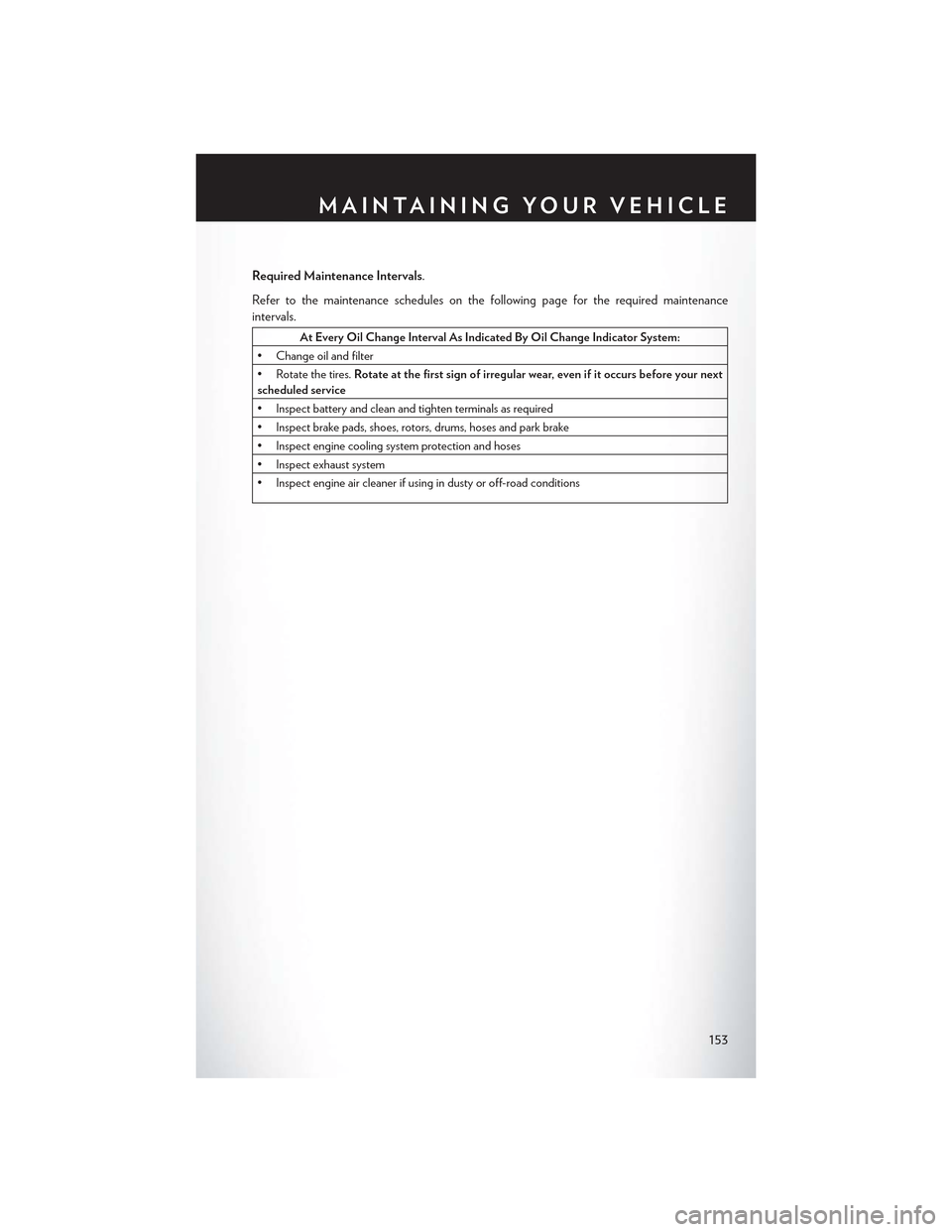
Required Maintenance Intervals.
Refer to the maintenance schedules on the following page for the required maintenance
intervals.
At Every Oil Change Interval As Indicated By Oil Change Indicator System:
• Change oil and filter
• Rotate the tires.Rotate at the first sign of irregular wear, even if it occurs before your nextscheduled service
•Inspectbatteryandcleanandtightenterminalsasrequired
•Inspectbrakepads,shoes,rotors,drums,hosesandparkbrake
•Inspectenginecoolingsystemprotectionandhoses
•Inspectexhaustsystem
•Inspectengineaircleanerifusingindustyoroff-roadconditions
MAINTAINING YOUR VEHICLE
153
Page 162 of 180

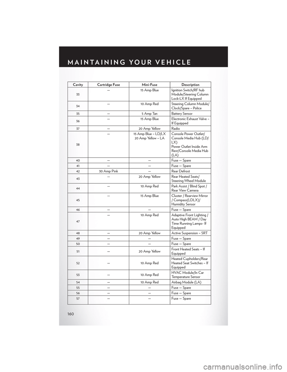
Cavity Cartridge FuseMini-FuseDescription
33—15 Amp Blue Ignition Switch/RF hubModule/Steering ColumnLock-LX If Equipped
34—10 Amp Red Steering Column Module/Clock/Spare – Police
35—5 Amp Tan Battery Sensor
36—15 Amp Blue Electronic Exhaust Valve –If Equipped
37—20 Amp Yellow Radio
38
—15 Amp Blue – LD/LX20 Amp Yellow – LAConsole Power Outlet/Console Media Hub (LD/LX)Power Outlet Inside ArmRest/Console Media Hub(LA)
40——Fuse — Spare
41——Fuse — Spare
4230 Amp Pink—Rear Defrost
43—20 Amp Yellow Rear Heated Seats/Steering Wheel Module
44—10 Amp Red Park Assist / Blind Spot /Rear View Camera
45—15 Amp Blue Cluster / Rearview Mirror/Compass(LDLX)/Humidity Sensor
46——Fuse — Spare
47
—10 Amp Red Adaptive Front Lighting /Auto High BEAM / DayTi m e R u n n i n g L a m p s- IfEquipped
48—20 Amp Yellow Active Suspension – SRT
49——Fuse — Spare
50——Fuse — Spare
51—20 Amp YellowFront Heated Seats – IfEquipped
52—10 Amp RedHeated Cupholders/RearHeated Seat Switches – IfEquipped
53—10 Amp RedHVAC Module/In CarTemperature Sensor
54—10 Amp Red Airbag Module (LA)
55——Fuse — Spare
56——Fuse — Spare
57——Fuse — Spare
MAINTAINING YOUR VEHICLE
160
Page 173 of 180

Access
Uconnect...............55
Access, Uconnect.............55
Adaptive Cruise Control (ACC) (Cruise
Control)................37
Adding Engine Coolant (Antifreeze) . . .152
Adding Washer Fluid...........152
Adjustable Pedals.............29Air BagAdvanced Front Air Bag........15Advance Front Air Bag.........15Air Bags . . . . . . . . . . . . . . . .15Air Bag Warning Light.........15Driver Knee Air Bag . . . . . . . . . .17Front Air Bag . . . . . . . . . . . . .15Passenger Knee Air Bag........17Rollover . . . . . . . . . . . . . . . .15Side Impacts..............15Air Bag Light . . . . . . . . . . . . . ..129Air Bag, Side . . . . . . . . . . . . . . . .15Air Cleaner, Engine (Engine Air CleanerFilter).................152Air Conditioner Maintenance.......152Air Conditioning............46, 47Air Conditioning Refrigerant.......152Air Conditioning System.........152AlarmVehicle Security Alarm.........14Alarm (Security Alarm)........14, 130Antifreeze (Engine Coolant).....150, 152Disposal................152Anti-Lock Warning Light.........129APPUconnect Access............57Appearance Care.............152Arming System (Security Alarm)......14Assistance Towing.............126Automatic Headlights...........33Automatic High Beams..........34Automatic Oil Change Indicator.....131Automatic Temperature Control (ATC) . .46Automatic Transmission..........43Adding Fluid.............151Fluid Type..............151Axle Fluid.................151Axle Lubrication..............151
Back-Up Camera . . . . . . . . . . . . .42
Battery..................152
Blind Spot Monitoring...........48
Body Mechanism Lubrication.......152
Brake Fluid................151
Brakes. . . . . . . . . . . . . . . . . ..152
BrakeSystem...............152
Fluid Check..............151
Master Cylinder...........152Warning Light............128Break-In Recommendations, New Vehicle. .31Bulb Replacement............166Bulbs, Light................166
Calibration, Compass...........119Capacities, Fluid.............150Caps, FillerOil (Engine).............152Car Washes................152Changing A Flat Tire...........132Charging System Light..........129Child Restraint...............18Child RestraintsCar Seat................18Child Restraints............18Child Tether Anchorage Locations . . .21Lower Anchors And Tethers ForChildren................18CleaningWheels................152Windshield Wiper Blades.......152Climate Control..............46Clock . . . . . . . . . . . . . . . . . ..118Cluster Warning/Indicator LightsAnti-Lock Brake (ABS) Light.....129Brake Warning Light..........128Charging System Light........129Electronic Throttle Control (ETC) Indica-tor Light...............129Engine Temperature Warning Light . .127Front Fog Light Indicator.......130High Beam Indicator.........130Oil Pressure Warning Light......129Ti re Pre s s u re M o n i t o r i n g S y s t e m ( T P M S )Light.................126Turn Signal Indicator.........130Vehicle Security Light.........130Clutch . . . . . . . . . . . . . . . . ..152Clutch Fluid................152
INDEX
171
Page 175 of 180

Glass Cleaning..............152
Hands-Free Phone (Uconnect)......109HeadlightsAutomatic...............33Cleaning...............152Dimmer Switch............34High Beam . . . . . . . . . . . . . .33Head Restraints..............22Head Rests.................22Heated Mirrors..............48Heated Seats................27High Beam Indicator...........130High Beam/Low Beam Select (Dimmer)Switch.................33HomeLink (Garage Door Opener) . . . .121Hood Release...............145
Identifying Your Radio...........54Instrument Cluster Indicator Lights . . . .130Instrument Panel Cover..........152Instrument Panel Lens Cleaning......152Interior And Instrument Lights.......5Interior Appearance Care.........152Intermittent Wipers (Delay Wipers)....32Introduction.................2In Vehicle FeaturesUconnect Access............61iPod/USB/MP3 ControlBluetooth Streaming Audio......109
Jacking Instructions............135Jack Location...............132Jack Operation..............135Jump Starting...............139
Key Fob . . . . . . . . . . . . . . . . . . .8Lock The Doors.............8Unlock The Doors............8Keyless Enter-N-Go............10Lock The Vehicle’s Doors........8Lock/Unlock............10, 11Starting/Stopping...........12
Lane Change Assist............32LaneSense.................42Lap/Shoulder Belts.............14
LATCH (Lower Anchors And Tether For
CHildren)................19
Light Bulbs................166
Lights
Fog . . . . . . . . . . . . . . . . ..130
High Beam Indicator.........130
SecurityAlarm............130
Service................166Tire Pressure Monitoring (TPMS) . .126LocksDoor . . . . . . . . . . . . . . . . . .8Lubrication, Body.............152
Maintenance Free Battery.........152Maintenance, General...........152Maintenance Procedures.........152Maintenance Record...........156Maintenance Schedule..........152Malfunction Indicator Light (CheckEngine)................128ManualTilt/Telescoping Steering Column . . .30Master Cylinder (Brakes).........152Memory Seat...............25MirrorsHeated................48MOPAR Accessories...........169
Navigation..............79, 103New Vehicle Break-In Period........31
Octane Rating, Gasoline (Fuel)......150Oil Change Indicator...........131Oil Change Indicator, Reset........131Oil, Engine..............150, 152Capacity...............150Change Interval.........131, 152Checking...............152Disposal...............152Filter...............150, 152Filter Disposal............152Materials Added To..........152Recommendation........150, 152Viscosity.............150, 152Oil Filter, Selection............152Oil Pressure Light.............129OutletPower . . . . . . . . . . . . . . . ..123
INDEX
173