wheel CHRYSLER 300 2015 2.G Owner's Guide
[x] Cancel search | Manufacturer: CHRYSLER, Model Year: 2015, Model line: 300, Model: CHRYSLER 300 2015 2.GPages: 180, PDF Size: 30.54 MB
Page 137 of 180

Jacking And Changing A Tire
1. Remove the spare tire, jack, and lug wrench.
2. If equipped with aluminum wheels where
the center cap covers the lug nuts, use the
lug wrench to pry the center cap off care-
fully before raising the vehicle.
3. Before raising the vehicle, use the lug
wrench to loosen, but not remove, the lug
nuts on the wheel with the flat tire. Turn the
lug nuts counterclockwise one turn while the
wheel is still on the ground.
4. Place the jack underneath the lift area that is
closest to the flat tire. Turn the jack screw
clockwise to firmly engage the jack saddle with the lift area of the sill flange.
Jacking Warning Label
WHAT TO DO IN EMERGENCIES
135
Page 139 of 180

7. Mount the spare tire.
NOTE:
•Forvehiclessoequipped,donotattempt
to install a center cap or wheel cover on
the compact spare.
•Referto“CompactSpareTire”andto
“Limited-Use Spare” under “Tires—
General Information” in “Starting and
Operating” in the Owner's Manual on
the DVD for additional warnings, cau-
tions, and information about the spare
tire, its use, and operation.
8. Install the lug nuts with the cone shaped end
of the lug nut toward the wheel. Lightly
tighten the lug nuts.
9. Lower the vehicle to the ground by turning the jack handle counterclockwise.
10. Finish tightening the lug nuts. Push down on the wrench while at the end of the handle for
increased leverage. Tighten the lug nuts in a star pattern until each nut has been tightened
twice. The correct tightness of each lug nut is 130 ft-lb. (176 N·m). If in doubt about the
correct tightness, have them checked with a torque wrench by your authorized dealer or at a
service station.
11. Stow the jack, tools and flat tire. Make sure the base of the jack faces the front of the vehicle
before tightening down the fastener.
Road Tire Installation
1. Mount the road tire on the axle.
2. Install the remaining lug nuts with the cone shaped end of the nut toward the wheel. Lightly
tighten the lug nuts.
3. Lower the vehicle to the ground by turning the jack handle counterclockwise.
4. Finish tightening the lug nuts. Push down on the wrench while at the end of the handle for
increased leverage. Tighten the lug nuts in a star pattern until each nut has been tightened
twice. The correct tightness of each lug nut is 130 ft-lbs (176 N·m). If in doubt about the
correct tightness, have them checked with a torque wrench by your authorized dealer or
service station.
5. After 25 miles (40 km) check the lug nut torque with a torque wrench to ensure that all lug nuts
are properly seated against the wheel.
Install Compact Spare
WHAT TO DO IN EMERGENCIES
137
Page 140 of 180

CAUTION!
Do not attempt to raise the vehicle by jacking on locations other than those indicated in the
Jacking Instructions for this vehicle.
WARNING!
•Donotattempttochangeatireonthesideofthevehicleclosetomovingtraffic.Pullfar
enough off the road to avoid the danger of being hit when operating the jack or changing
the wheel.
•Beingunderajacked-upvehicleisdangerous.Thevehiclecouldslipoffthejackandfallon
you. You could be crushed. Never put any part of your body under a vehicle that is on a
jack.
•Neverstartorruntheenginewhilethevehicleisonajack.Ifyouneedtogetunderaraised
vehicle, take it to a service center where it can be raised on a lift.
• The jack is designed to be used as a tool for changing tires only. The jack should not be
used to lift the vehicle for service purposes. The vehicle should be jacked on a firm level
surface only. Avoid ice or slippery areas.
•Aloosetireorjackthrownforwardinacollisionorhardstopcouldendangertheoccupants
of the vehicle. Always stow the jack parts and the spare tire in the places provided.
•Carefullyfollowthesetirechangingwarningstohelppreventpersonalinjuryordamageto
your vehicle:
•Alwaysparkonafirm,levelsurfaceasfarfromtheedgeoftheroadwayaspossiblebefore
raising the vehicle.
• Turn on the Hazard Warning flasher.
• Block the wheel diagonally opposite the wheel to be raised.
•SettheparkingbrakefirmlyandsetanautomatictransmissioninPARK;amanual
transmission in REVERSE.
•Donotletanyonesitinthevehiclewhenitisonajack.
•Donotgetunderthevehiclewhenitisonajack.
•Onlyusethejackinthepositionsindicatedandforliftingthisvehicleduringatirechange.
•Ifworkingonorneararoadway,beextremelycarefulofmotortraffic.
•Raisingthevehiclehigherthannecessarycanmakethevehiclelessstable.Itcouldslipoff
the jack and hurt someone near it. Raise the vehicle only enough to remove the tire.
•Toavoidtheriskofforcingthevehicleoffthejack,donotfullytightenthewheelnutsuntil
the vehicle has been lowered. Failure to follow this warning may result in personal injury.
•Aloosetireorjackthrownforwardinacollisionorhardstopcouldendangertheoccupants
of the vehicle. Always stow the jack parts and the spare tire in the places provided.
•Thelimited-usesparetiresareforemergencyuseonly.Installationofthislimited-usespare
tire affects vehicle handling. With this tire, do not drive more than 60 mph (100 km/h).
Keep inflated to the cold tire inflation pressure listed on either your tire placard or
limited-use spare tire and wheel assembly. Replace (or repair) the original tire at the first
opportunity and reinstall it on your vehicle. Failure to do so could result in loss of vehicle
control.
WHAT TO DO IN EMERGENCIES
138
Page 144 of 180

To R e s e t T h e M a n u a l P a r k R e l e a s e :
1. Push the latch (at the base of the lever, on the rear side) rearward (away from the lever) to
unlatch the lever.
2. Rotate the Manual Park Release lever forward and down, to its original position, until the
locking tab snaps into place to secure the lever.
3. Pull up gently on the tether strap to confirm that the lever is locked in its stowed position.
4. Tuck the tether strap into the base of the console. Reinstall the console storage bin.
TOWING A DISABLED VEHICLE
This section describes procedures for towing a disabled vehicle using a commercial towing
service.
Towing ConditionWheels OFF TheGroundRWD MODELS AWD MODELS
Flat TowNONE
If transmission is op-erable:• Transmission inNEUTRAL• 30 mph (48 km/h)maxspeed• 30 miles (48 km)maxdistance
NOT ALLOWED
Wheel Lift or DollyTo w
Front
NOT RECOM-MENDED (but, ifused, same limita-tions as above)
NOT ALLOWED
RearNOT RECOM-MENDED
NOT RECOM-MENDED, but, if used:• Ignition in ON/RUN position• Transmission
inNEUTRAL
(NOT in Park)
FlatbedALLBEST METHOD BEST METHOD
Refer to your Owner’s Manual on the DVD for further information.
WHAT TO DO IN EMERGENCIES
142
Page 145 of 180

FREEING A STUCK VEHICLE
If your vehicle becomes stuck in mud, sand or snow, it can often be moved using a rocking motion.
Tu r n t h e s t e e r i n g w h e e l r i g h t a n d l e f t t o c l e a r t h e a r e a a r o u n d t h e f r o n t w h e e l s . T h e n , s h i f t b a c k
and forth between REVERSE and DRIVE, while gently pushing the accelerator. Use the least
amount of accelerator pedal pressure that will maintain the rocking motion, without spinning the
wheels or racing the engine.
NOTE:
•ShiftsbetweenDRIVEandREVERSEcanonlybeachievedatwheelspeedsof5mph(8
km/h) or less. Whenever the transmission remains in NEUTRAL for more than 2 seconds, you
must push the brake pedal to engage DRIVE or REVERSE.
•Pushthe“ESCOff”switch,toplacetheElectronicStabilityControl(ESC)systemin“Partial
Off ” mode, before rocking the vehicle. Once the vehicle has been freed, push the “ESC Off ”
switch again to restore "ESC On" mode.
CAUTION!
•When“rocking”astuckvehiclebyshiftingbetweenREVERSEandDRIVE,donotspin
the wheels faster than 15 mph (24 km/h), or drivetrain damage may result.
•Revvingtheengineorspinningthewheelstoofastmayleadtotransmissionoverheating
and failure. It can also damage the tires. Do not spin the wheels above 30 mph (48 km/h)
while in gear (no transmission shifting occurring).
WARNING!
Fast spinning tires can be dangerous. Forces generated by excessive wheel speeds may cause
tire damage or failure. A tire could explode and injure someone. Do not spin your vehicle's
wheels faster than 30 mph (48 km/h) when you are stuck. Do not let anyone near a spinning
wheel, no matter what the speed.
WHAT TO DO IN EMERGENCIES
143
Page 156 of 180

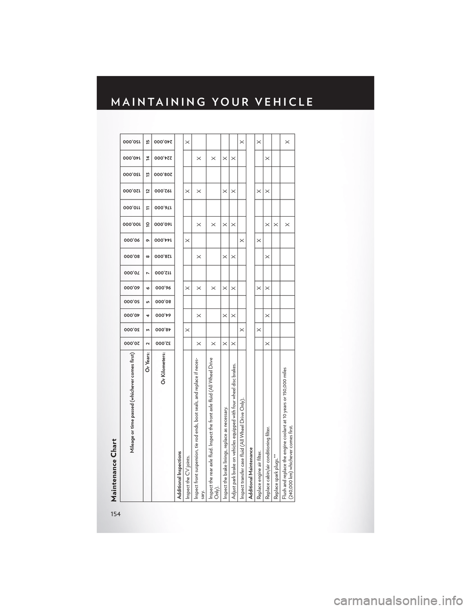
Maintenance Chart
Mileage or time passed (whichever comes first)
20,000
30,000
40,000
50,000
60,000
70,000
80,000
90,000
100,000
110,000
120,000
130,000
140,000
150,000
Or Years: 2 3 4 5 6 7 8 9 10 11 12 13 14 15
Or Kilometers:
32,000
48,000
64,000
80,000
96,000
112,000
128,000
144,000
160,000
176,000
192,000
208,000
224,000
240,000
Additional InspectionsInspect the CV joints. X X X X XInspect front suspension, tie rod ends, boot seals, and replace if neces-sary.
XXX X X X X
Inspect the rear axle fluid. Inspect the front axle fluid (All Wheel DriveOnly).
XX X X
Inspect the brake linings, replace as necessary.
XXX
X
X
X
X
Adjust park brake on vehicles equipped with four wheel disc brakes. X X X
X
X
X
X
Inspect transfer case fluid (All Wheel Drive Only).
X
X
X
Additional MaintenanceReplace engine air filter.
X
X
X
X
X
Replace cabin/air conditioning filter.
XXX
X
X
X
X
Replace spark plugs.**
X
Flush and replace the engine coolant at 10 years or 150,000 miles(240,000 km) whichever comes first.
XX
MAINTAINING YOUR VEHICLE
154
Page 157 of 180

Mileage or time passed (whichever comes first)
20,000
30,000
40,000
50,000
60,000
70,000
80,000
90,000
100,000
110,000
120,000
130,000
140,000
150,000
Or Years: 2 3 4 5 6 7 8 9 10 11 12 13 14 15
Or Kilometers:
32,000
48,000
64,000
80,000
96,000
112,000
128,000
144,000
160,000
176,000
192,000
208,000
224,000
240,000
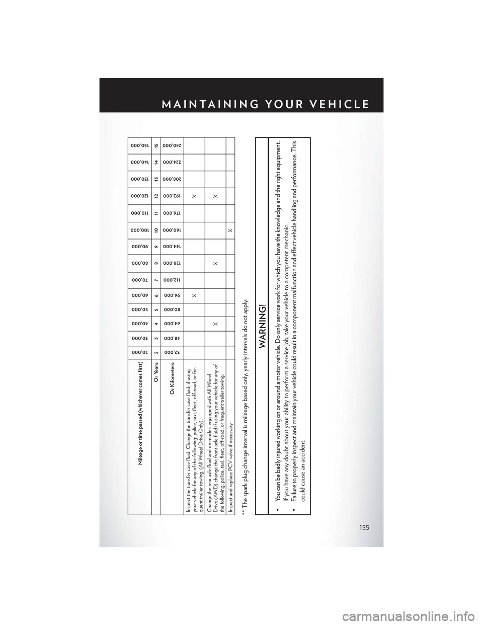
Inspect the transfer case fluid. Change the transfer case fluid; if usingyour vehicle for any of the following: police, taxi, fleet, off-road, or fre-quent trailer towing. (All Wheel Drive Only).
XX
Change the rear axle fluid and on models equipped with All WheelDrive (AWD) change the front axle fluid if using your vehicle for any ofthe following: police, taxi, fleet, off-road, or frequent trailer towing.
XX X
Inspect and replace PCV valve if necessary.
X
** The spark plug change interval is mileage based only, yearly intervals do not apply.
WARNING!
•Youcanbebadlyinjuredworkingonoraroundamotorvehicle.Doonlyserviceworkforwhichyouhavetheknowledgeandtherightequipment.
If you have any doubt about your ability to perform a service job, take your vehicle to a competent mechanic.
•Failuretoproperlyinspectandmaintainyourvehiclecouldresultinacomponentmalfunctionandeffectvehiclehandlingandperformance.This
could cause an accident.
MAINTAINING YOUR VEHICLE
155
Page 159 of 180

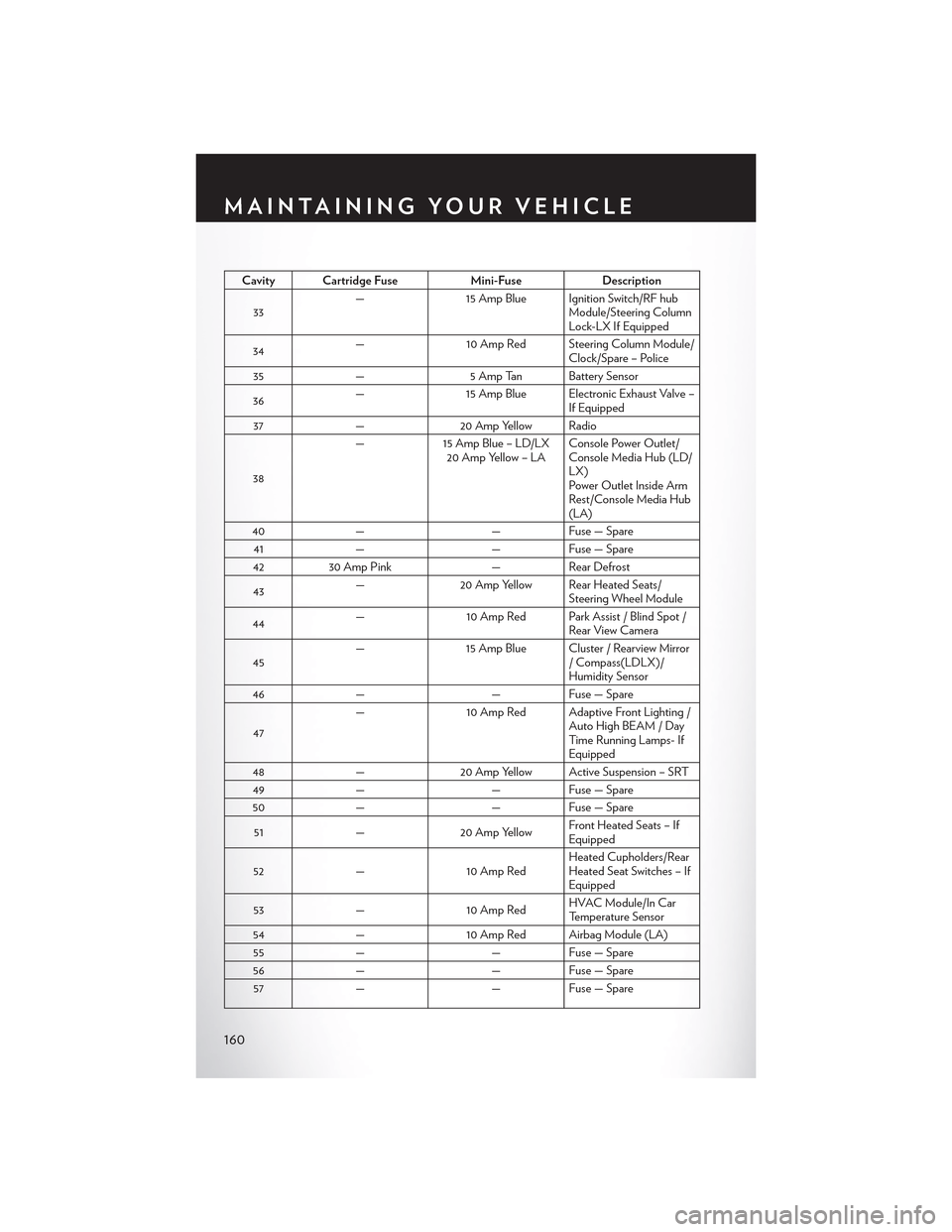
FUSES
Front Power Distribution Center (Fuses)
The Front Power Distribution Center is located in the engine compartment. This module
contains fuses and relays.
CAUTION!
•Wheninstallingthepowerdistributioncentercover,itisimportanttoensurethecoveris
properly positioned and fully latched. Failure to do so may allow water to get into the
power distribution center and possibly result in an electrical system failure.
• When replacing a blown fuse, it is important to use only a fuse having the correct
amperage rating. The use of a fuse with a rating other than indicated may result in a
dangerous electrical system overload. If a properly rated fuse continues to blow, it
indicates a problem in the circuit that must be corrected.
Cavity Cartridge Fuse Mini-FuseDescription
1––Fuse – Spare
2 40 Amp Green–Radiator Fan #1 – If Equipped
3 50 Amp Red–Power Steering #1 / Radiator Fan(6.2L Supercharged) – If Equipped
4 30 Amp Pink–Starter
5 40 Amp Green–Electronic Stability Control
6 30 Amp Pink–Electronic Stability Control
7––Fuse – Spare
8 20 Amp Blue–Police Ignition Run / ACC # 2
9–20 Amp Yellow All-Wheel Drive Module – If Equipped
10–10 Amp Red Security – If Equipped / Under hoodLamp – Police
11–20 Amp YellowHorns
12–10 Amp RedAir Conditioning Clutch
13––Fuse – Spare
14––Fuse – Spare
15–20 Amp YellowLeft HID – If Equipped
16–20 Amp Yellow Right HID – If Equipped
18 50 Amp Red–Radiator Fan #2 – If Equipped
19 50 Amp Red–Power Steering #2 / Radiator Fan(6.2L Supercharged)
20 30 Amp Pink–Wiper Motor
21 30 Amp Pink– Headlamp Washers – If Equipped / Po-lice Feed
MAINTAINING YOUR VEHICLE
157
Page 162 of 180

Cavity Cartridge FuseMini-FuseDescription
33—15 Amp Blue Ignition Switch/RF hubModule/Steering ColumnLock-LX If Equipped
34—10 Amp Red Steering Column Module/Clock/Spare – Police
35—5 Amp Tan Battery Sensor
36—15 Amp Blue Electronic Exhaust Valve –If Equipped
37—20 Amp Yellow Radio
38
—15 Amp Blue – LD/LX20 Amp Yellow – LAConsole Power Outlet/Console Media Hub (LD/LX)Power Outlet Inside ArmRest/Console Media Hub(LA)
40——Fuse — Spare
41——Fuse — Spare
4230 Amp Pink—Rear Defrost
43—20 Amp Yellow Rear Heated Seats/Steering Wheel Module
44—10 Amp Red Park Assist / Blind Spot /Rear View Camera
45—15 Amp Blue Cluster / Rearview Mirror/Compass(LDLX)/Humidity Sensor
46——Fuse — Spare
47
—10 Amp Red Adaptive Front Lighting /Auto High BEAM / DayTi m e R u n n i n g L a m p s- IfEquipped
48—20 Amp Yellow Active Suspension – SRT
49——Fuse — Spare
50——Fuse — Spare
51—20 Amp YellowFront Heated Seats – IfEquipped
52—10 Amp RedHeated Cupholders/RearHeated Seat Switches – IfEquipped
53—10 Amp RedHVAC Module/In CarTemperature Sensor
54—10 Amp Red Airbag Module (LA)
55——Fuse — Spare
56——Fuse — Spare
57——Fuse — Spare
MAINTAINING YOUR VEHICLE
160
Page 164 of 180

WARNING!
•Overloadingofyourtiresisdangerous.Overloadingcancausetirefailure,affectvehicle
handling, and increase your stopping distance. Use tires of the recommended load
capacity for your vehicle.Neveroverloadthem.
• Improperly inflated tires are dangerous and can cause collisions. Under-inflation increases
tire flexing and can result in over-heating and tire failure. Over-inflation reduces a tire’s
ability to cushion shock. Objects on the road and chuck holes can cause damage that
results in tire failure. Unequal tire pressures can cause steering problems. You could lose
control of your vehicle. Over-inflated or under-inflated tires can affect vehicle handling
and can fail suddenly, resulting in loss of vehicle control. Always drive with each tire inflated
to the recommended cold tire inflation pressure.
SPARE TIRES — IF EQUIPPED
NOTE:
For vehicles equipped with Tire Service Kit instead of a spare tire, please refer to “Tire Service Kit”
in “What To Do In Emergencies” on your DVD for further information.
CAUTION!
Because of the reduced ground clearance, do not take your vehicle through an automatic car
wash with a compact or limited-use temporary spare installed. Damage to the vehicle may
result.
Spare Tire Matching Original Equipped Tire And Wheel — If Equipped
Yo u r v e h i c l e m a y b e e q u i p p e d w i t h a s p a r e t i r e a n d w h e e l e q u i v a l e n t i n l o o k a n d f u n c t i o n t o t h e
original equipment tire and wheel found on the front or rear axle of your vehicle. This spare tire
may be used in the tire rotation for your vehicle. If your vehicle has this option, refer to an
authorized tire dealer for the recommended tire rotation pattern.
Compact Spare Tire — If Equipped
The compact spare is for temporary emergency use only. You can identify if your vehicle is
equipped with a compact spare by looking at the spare tire description on the Tire and Loading
Information Placard located on the driver’s side door opening or on the sidewall of the tire.
Compact spare tire descriptions begin with the letter “T” or “S” preceding the size designation.
Example: T145/80D18 103M.
T, S = Temporary Spare Tire
Since this tire has limited tread life, the original equipment tire should be repaired (or replaced)
and reinstalled on your vehicle at the first opportunity.
MAINTAINING YOUR VEHICLE
162