display CHRYSLER 300 2015 2.G User Guide
[x] Cancel search | Manufacturer: CHRYSLER, Model Year: 2015, Model line: 300, Model: CHRYSLER 300 2015 2.GPages: 180, PDF Size: 30.54 MB
Page 3 of 180
INTRODUCTION/WELCOME
WELCOME FROM FCA US LLC . . . . . . . 2
CONTROLS AT A GLANCE
DRIVER COCKPIT...............4INSTRUMENT CLUSTER...........6
GETTING STARTED
KEY FOB . . . . . . . . . . . . . . . . . . . . 8REMOTE START...............10KEYLESS ENTER-N-GO™..........10VEHICLE SECURITY ALARM . .......14SEAT BELT SYSTEMS.............14SUPPLEMENTAL RESTRAINT SYSTEM (SRS)—AIRBAGS . . . . . . . . . . . . . . . . . . 15CHILD RESTRAINTS.............18HEAD RESTRAINTS..............22FRONT SEATS . . . . . . . . . . . . . . . . 24REAR SEAT...................27HEATED SEATS . . . . . . . . . . . . . . . . 27HEATED AND COOLED CUPHOLDERS...28ADJUSTABLE PEDALS............29TILT/TELESCOPING STEERINGCOLUMN . . . . . . . . . . . . . . . . . . . 30
OPERATING YOUR VEHICLE
ENGINE BREAK-INRECOMMENDATIONS............31TURN SIGNAL/WIPER/WASHER/HIGH BEAMLEVER.....................32HEADLIGHT SWITCH............33ELECTRONIC SPEED CONTROL.....35ADAPTIVE CRUISE CONTROL (ACC) . . . 37LANESENSE..................42PA R K V I E W ® R E A R B AC K- U P C A M E R A . . 4 2EIGHT-SPEED AUTOMATICTRANSMISSION................43AUTOSTICK . . . . . . . . . . . . . . . . . . 44AUTOMATIC TEMPERATURE CONTROLS(ATC) . . . . . . . . . . . . . . . . . . . . . 46BLIND SPOT MONITORING........48POWER SUNROOF..............49WIND BUFFETING..............51
ELECTRONICS
YO U R V E H I C L E ' S S O U N D SYS T E M....52IDENTIFYING YOUR RADIO........54Uconnect® ACCESS..............55Uconnect® 8.4A.................71Uconnect® 8.4AN...............94Uconnect® PHONE ..............109STEERING WHEEL AUDIO CONTROLS...118SETTING THE ANALOG CLOCK.....118DRIVER INFORMATION DISPLAY (DID). . 119PROGRAMMABLE FEATURES.......120UNIVERSAL GARAGE DOOR OPENER(HomeLink®)..................121
POWER OUTLETS.............123
UTILITY
TRAILER TOWING WEIGHTS (MAXIMUMTRAILER WEIGHT RATINGS).......124RECREATIONAL TOWING (BEHINDMOTORHOME, ETC.)...........125
WHAT TO DO IN EMERGENCIES
ROADSIDE ASSISTANCE..........126INSTRUMENT CLUSTER WARNINGLIGHTS . . . . . . . . . . . . . . . . . . . . 126INSTRUMENT CLUSTER INDICATORLIGHTS . . . . . . . . . . . . . . . . . . . . 130IF YOUR ENGINE OVERHEATS......132JACKING AND TIRE CHANGING.....132BATTERY LOCATION............139JUMP-STARTING..............139MANUAL PARK RELEASE..........141TOWING A DISABLED VEHICLE.....142FREEING A STUCK VEHICLE.......143EVENT DATA RECORDER (EDR).....144
MAINTAINING YOUR VEHICLE
OPENING THE HOOD . . .........145ENGINE COMPARTMENT — 3.6L.....146ENGINE COMPARTMENT — 5.7L.....148FLUID CAPACITIES . . . . . . . . . . . . . 150FLUIDS, LUBRICANTS, AND GENUINEPA RTS . . . . . . . . . . . . . . . . . . . . . 1 5 0MAINTENANCE PROCEDURES . . . . . . 152MAINTENANCE SCHEDULE . . .....152FUSES.....................157TIRE PRESSURES...............161SPARE TIRES — IF EQUIPPED . . . . . . . 162FUEL DOOR RELEASE ...........164WHEEL AND WHEEL TRIM CARE.....165REPLACEMENT BULBS...........166
CONSUMER ASSISTANCE
FCA US LLC CUSTOMER CENTER . . . . 167FCA CANADA INC. CUSTOMERCENTER...................167PUBLICATIONS ORDERING........167ASSISTANCE FOR THE HEARINGIMPAIRED . . . . . . . . . . . . . . . . . . 167REPORTING SAFETY DEFECTS IN THEUNITED STATES . . . . . . . . . . . . . . . 168
MOPAR® ACCESSORIES
AUTHENTIC ACCESSORIES BYMOPAR® . . . . . . . . . . . . . . . . . . . 169
FREQUENTLY ASKED QUESTIONSFREQUENTLY ASKED QUESTIONS....170
INDEX................... 171
TA B L E O F CO N T E N TS
Page 6 of 180
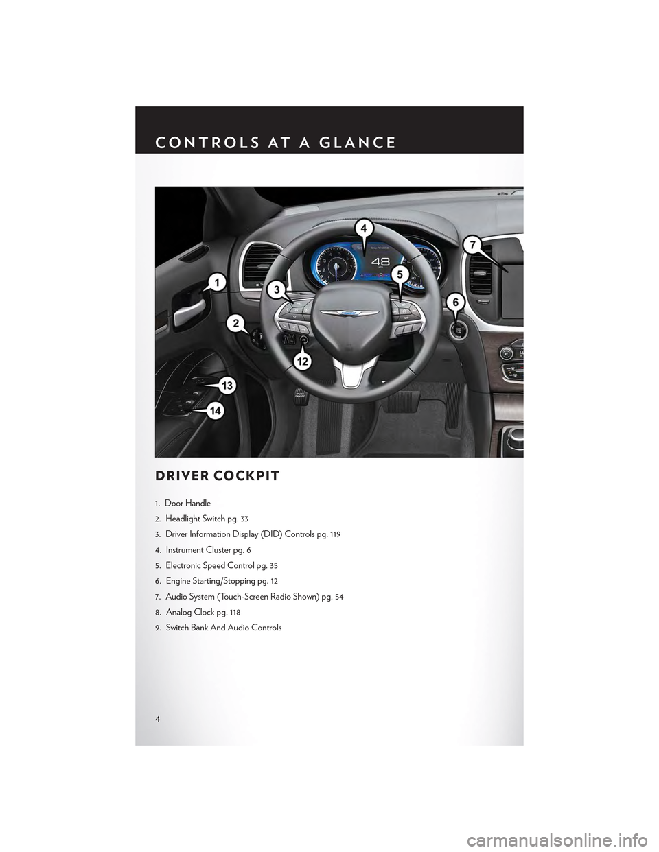
DRIVER COCKPIT
1. Door Handle
2. Headlight Switch pg. 33
3. Driver Information Display (DID) Controls pg. 119
4. Instrument Cluster pg. 6
5. Electronic Speed Control pg. 35
6. Engine Starting/Stopping pg. 12
7. Audio System (Touch-Screen Radio Shown) pg. 54
8. Analog Clock pg. 118
9. Switch Bank And Audio Controls
CONTROLS AT A GLANCE
4
Page 8 of 180
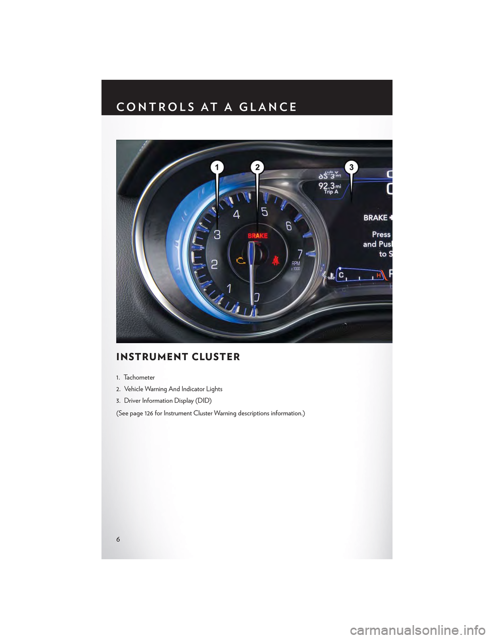
INSTRUMENT CLUSTER
1. Tachometer
2. Vehicle Warning And Indicator Lights
3. Driver Information Display (DID)
(See page 126 for Instrument Cluster Warning descriptions information.)
CONTROLS AT A GLANCE
6
Page 16 of 180
VEHICLE SECURITY ALARM
The Vehicle Security Alarm monitors the vehicle doors for unauthorized entry and the Keyless
Enter-N-Go™ START/STOP button for unauthorized operation. While the Vehicle Security
Alarm is armed, interior switches for door locks and decklid release are disabled. If something
triggers the alarm, the Vehicle Security Alarm will provide the following audible and visible
signals: the horn will pulse, the park lamps and/or turn signals will flash, and the Vehicle Security
Light in the instrument cluster will flash.
To A r m :
•PushtheKeylessEnter-N-Go™START/STOPbuttonuntiltheDriverInformationDisplay
(DID) indicates that the vehicle ignition is “OFF.” Push the power door lock switch while the
door is open, push the Key Fob LOCK button, or with one of the Key Fobs located outside the
vehicle and within 5 ft (1.5 m) of the driver's and passenger front door handles, push the
Keyless Enter-N-Go™ LOCK button located on the door handle.
NOTE:
After pushing the Keyless Enter-N-Go™ LOCK button, you must wait two seconds before youcan lock or unlock the vehicle via the door handle.
To D i s a r m :
•PushtheKeyFobUNLOCKbuttonorwithoneoftheKeyFobslocatedoutsidethevehicle
and within 5 ft (1.5 m) of the driver's and passenger front door handles, grab the Keyless
Enter-N-Go™ door handle and enter the vehicle, then push the Keyless Enter-N-Go™ START/
STOP button (requires at least one valid Key Fob in the vehicle).
SEAT BELT SYSTEMS
Lap/Shoulder Belts
•Allseatingpositionsinyourvehicleareequippedwithlap/shoulderbelts.
•Besureeveryoneinyourvehicleisinaseatandusingaseatbeltproperly.
•Positionthelapbeltsothatitissnugandlieslowacrossyourhips,belowyourabdomen.To
remove slack in the lap belt portion, pull up on the shoulder belt. To loosen the lap belt if it is
too tight, tilt the latch plate and pull on the lap belt. A snug seat belt reduces the risk of sliding
under the seat belt in a collision.
• Position the shoulder belt across the shoulder and chest with minimal, if any slack so that it is
comfortable and not resting on your neck. The retractor will withdraw any slack in the shoulder
belt.
Seat Belt Pretensioner
•Thefrontseatbeltsystemisequippedwithpretensioningdevicesthataredesignedtoremove
slack from the seat belt in the event of a collision.
•Adeployedpretensioneroradeployedairbagmustbereplacedimmediately.
GETTING STARTED
14
Page 37 of 180
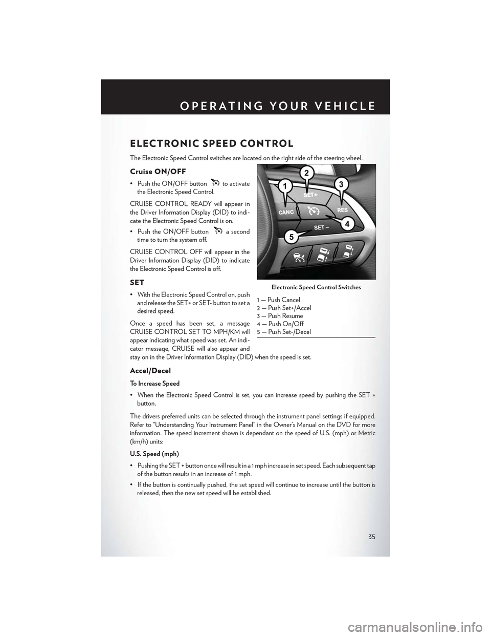
ELECTRONIC SPEED CONTROL
The Electronic Speed Control switches are located on the right side of the steering wheel.
Cruise ON/OFF
• Push the ON/OFF buttonto activate
the Electronic Speed Control.
CRUISE CONTROL READY will appear in
the Driver Information Display (DID) to indi-
cate the Electronic Speed Control is on.
• Push the ON/OFF buttona second
time to turn the system off.
CRUISE CONTROL OFF will appear in the
Driver Information Display (DID) to indicate
the Electronic Speed Control is off.
SET
• With the Electronic Speed Control on, push
and release the SET+ or SET- button to set a
desired speed.
Once a speed has been set, a message
CRUISE CONTROL SET TO MPH/KM will
appear indicating what speed was set. An indi-
cator message, CRUISE will also appear and
stay on in the Driver Information Display (DID) when the speed is set.
Accel/Decel
To Increase Speed
•WhentheElectronicSpeedControlisset,youcanincreasespeedbypushingtheSET+
button.
The drivers preferred units can be selected through the instrument panel settings if equipped.
Refer to “Understanding Your Instrument Panel” in the Owner’s Manual on the DVD for more
information. The speed increment shown is dependant on the speed of U.S. (mph) or Metric
(km/h) units:
U.S. Speed (mph)
• Pushing the SET+button once will result in a 1 mph increase in set speed. Each subsequent tap
of the button results in an increase of 1 mph.
• If the button is continually pushed, the set speed will continue to increase until the button is
released, then the new set speed will be established.
Electronic Speed Control Switches
1 — Push Cancel2—PushSet+/Accel3 — Push Resume4 — Push On/Off5 — Push Set-/Decel
OPERATING YOUR VEHICLE
35
Page 39 of 180
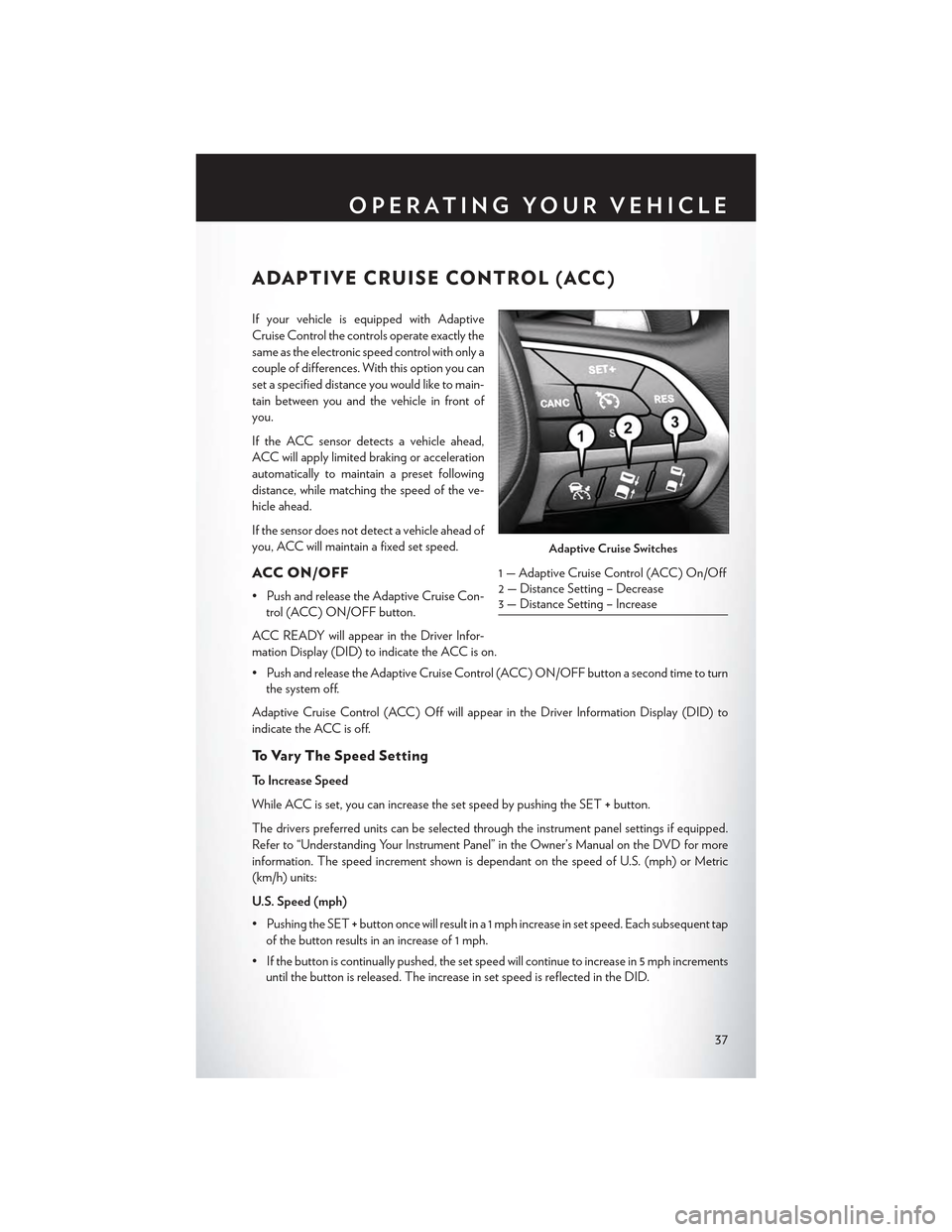
ADAPTIVE CRUISE CONTROL (ACC)
If your vehicle is equipped with Adaptive
Cruise Control the controls operate exactly the
same as the electronic speed control with only a
couple of differences. With this option you can
set a specified distance you would like to main-
tain between you and the vehicle in front of
you.
If the ACC sensor detects a vehicle ahead,
ACC will apply limited braking or acceleration
automatically to maintain a preset following
distance, while matching the speed of the ve-
hicle ahead.
If the sensor does not detect a vehicle ahead of
you, ACC will maintain a fixed set speed.
ACC ON/OFF
•PushandreleasetheAdaptiveCruiseCon-
trol (ACC) ON/OFF button.
ACC READY will appear in the Driver Infor-
mation Display (DID) to indicate the ACC is on.
•PushandreleasetheAdaptiveCruiseControl(ACC)ON/OFFbuttonasecondtimetoturn
the system off.
Adaptive Cruise Control (ACC) Off will appear in the Driver Information Display (DID) to
indicate the ACC is off.
To V a r y T h e S p e e d S e t t i n g
To Increase Speed
While ACC is set, you can increase the set speed by pushing the SET+button.
The drivers preferred units can be selected through the instrument panel settings if equipped.
Refer to “Understanding Your Instrument Panel” in the Owner’s Manual on the DVD for more
information. The speed increment shown is dependant on the speed of U.S. (mph) or Metric
(km/h) units:
U.S. Speed (mph)
• Pushing the SET+button once will result in a 1 mph increase in set speed. Each subsequent tap
of the button results in an increase of 1 mph.
• If the button is continually pushed, the set speed will continue to increase in 5 mph increments
until the button is released. The increase in set speed is reflected in the DID.
Adaptive Cruise Switches
1—AdaptiveCruiseControl(ACC)On/Off2 — Distance Setting – Decrease3 — Distance Setting – Increase
OPERATING YOUR VEHICLE
37
Page 41 of 180
Distance Setting (ACC Only)
The specified following distance for ACC can be set by varying the distance setting between four
bars (longest), three bars (long), two bars (medium) and one bar (short). Using this distance
setting and the vehicle speed, ACC calculates and sets the distance to the vehicle ahead. This
distance setting displays in the DID.
• To increase the distance setting, push the Distance Setting—Increase button and release. Each
time the button is pushed, the distance setting increases by one bar (longer).
• To decrease the distance setting, push the Distance Setting—Decrease button and release.
Each time the button is pushed, the distance setting decreases by one bar (shorter).
Changing Modes (ACC Only)
If desired, the Adaptive Cruise Control mode can be turned off and the system can be operated
as a normal (Fixed Speed) Speed Control mode. When in the normal (Fixed Speed) Speed
Control mode the distance setting feature will be disabled and the system will maintain the speed
you set.
• To change between the different cruise control modes, push the ADAPTIVE CRUISE
CONTROL (ACC ) ON/OFF button which turns the ACC and the normal (Fixed Speed)
Speed Control OFF.
•Pushingthenormal(FixedSpeed)SPEEDCONTROLON/OFFbuttonwillresultinturning
ON (changing to) the normal (Fixed Speed) Speed Control mode.
Refer to your Owner's Manual on the DVD for further information.
OPERATING YOUR VEHICLE
39
Page 42 of 180
WARNING!
Adaptive Cruise Control (ACC) is a convenience system. It is not a substitute for activedriving involvement. It is always the driver’s responsibility to be attentive of road, traffic, andweather conditions, vehicle speed, distance to the vehicle ahead; and, most importantly, brakeoperation to ensure safe operation of the vehicle under all road conditions. Your completeattention is always required while driving to maintain safe control of your vehicle. Failure tofollow these warnings can result in a collision and death or serious personal injury.The ACC system:•Doesnotreacttopedestrians,oncomingvehicles,andstationaryobjects(e.g.,astopped
vehicle in a traffic jam or a disabled vehicle).
• Cannot take street, traffic, and weather conditions into account, and may be limited upon
adverse sight distance conditions.
•Doesnotalwaysfullyrecognizecomplexdrivingconditions,whichcanresultinwrongor
missing distance warnings.
•Willbringthevehicletoacompletestopwhilefollowingatargetvehicleandholdthevehicle for 2 seconds in the stop position. If the target vehicle does not start moving withintwo seconds the ACC system will display a message that the system will release the brakesand that the brakes must be applied manually. An audible chime will sound when thebrakes are released.
Yo u s h o u l d s w i t c h o f f t h e A C C s y s t e m :
• When driving in fog, heavy rain, heavy snow, sleet, heavy traffic, and complex driving
situations (i.e., in highway construction zones).
• When entering a turn lane or highway off ramp; when driving on roads that are winding, icy,
snow-covered, slippery, or have steep uphill or downhill slopes.
• When towing a trailer up or down steep slopes.
• When circumstances do not allow safe driving at a constant speed.
The Cruise Control system has two control modes:
•AdaptiveCruiseControlmodeformaintaininganappropriatedistancebetweenvehicles.• Normal (fixed speed) electronic speed control mode for cruising at a constant presetspeed. For additional information, refer to “Normal (Fixed Speed) Cruise Control Mode”in this section.
Normal (fixed speed) electronic speed control will not react to preceding vehicles. Always be
aware of the mode selected.
You can change the mode by using the Cruise Control buttons. The two control modes
function differently. Always confirm which mode is selected.
FORWARD COLLISION WARNING (FCW)
The Forward Collision Warning (FCW) system provides the driver with audible warnings and
visual warnings within the Driver Information Display (DID), to warn the driver when it detects a
potential frontal collision. The warnings are intended to provide the driver with enough time to
react, avoid or mitigate the potential collision.
NOTE:
FCW monitors the information from the forward looking sensors as well as the Electronic Brake
Controller (EBC ), to calculate the probability of a forward collision. When the system determines
that a forward collision is probable, the driver will be provided with audible and visual warnings.
OPERATING YOUR VEHICLE
40
Page 43 of 180
Turning FCW ON Or OFF
The forward collision button is located on the switch panel below the Uconnect® display.
•ToturntheFCWsystemOFF,pushtheforwardcollisionbuttononce(LEDturnson).
•ToturntheFCWsystembackON,pushtheforwardcollisionbuttonagain(LEDturnsoff).
NOTE:
The default status of FCW is “On”, this allows the system to warn you of a possible collision
with the vehicle in front of you.
Changing the FCW status to “Off ” prevents the system from warning you of a possible collision
with the vehicle in front of you. If FCW is set to “Off ”, “FCW OFF” will be displayed in the Driver
Information Display (DID).
Changing FCW Status
The FCW feature has two settings and can be changed within the Uconnect® System Screen:
•Far
• Near
Far
The default status of FCW is the “Far” setting.
The far setting provides warnings for potential collisions more distant in front of the vehicle,
allowing the driver to have the most reaction time to avoid a collision.
More cautious drivers that do not mind frequent warnings may prefer this setting.
NOTE:
This setting gives you the most reaction time.
Near
Changing the FCW status to the “Near” setting, allows the system to warn you of a potential
frontal collision when you are much closer.
This setting provides less reaction time than the “Far” setting, which allows for a more dynamic
driving experience.
More dynamic or aggressive drivers that want to avoid frequent warnings may prefer this setting.
Refer to the Owner's Manual on the DVD for further details.
WARNING!
Forward Collision Warning (FCW ) is not intended to avoid a collision on its own, nor can
FCW detect every type of potential collision. The driver has the responsibility to avoid a
collision by controlling the vehicle via braking and steering. Failure to follow this warning could
lead to serious injury or death.
OPERATING YOUR VEHICLE
41
Page 44 of 180
LANESENSE
The LaneSense system can be enabled and disabled with the LaneSense button, located on the
switch panel below the Uconnect® display.
• Push the LaneSense buttonto turn the system ON (LED turns off ).
The LaneSense system is operational at speeds above 37 mph (60 km/h) and below 112 mph(180 km/h). The LaneSense system uses a forward looking camera to detect lane markings andmeasure vehicle position within the lane boundaries.
When both lane markings are detected and the driver unintentionally drifts out of the lane (noturn signal applied), the LaneSense system provides a haptic warning in the form of torqueapplied to the steering wheel to prompt the driver to remain within the lane boundaries. If thedriver continues to unintentionally drift out of the lane, the LaneSense system provides a visualwarning through the Driver Information Display (DID) to prompt the driver to remain within thelane boundaries.
The driver may manually override the haptic warning by applying torque into the steering wheelat any time.
When only a single lane marking is detected and the driver unintentionally drifts across the lanemarking (no turn signal applied), the LaneSense system provides a visual warning through theDriver Information Display (DID) to prompt the driver to remain within the lane. When only asingle lane marking is detected, a haptic (torque) warning will not be provided.
Refer to your Owner's Manual on the DVD for further details.
NOTE:
When operating conditions have been met, the LaneSense system will monitor if the driver’shands are on the steering wheel and provides an audible warning to the driver when the driver’shands are not detected on the steering wheel. The system will cancel if the driver does not returntheir hands to the wheel.
PA R K V I E W ® R E A R B AC K- U P C A M E R A
Yo u c a n s e e a n o n - s c r e e n i m a g e o f t h e r e a r o f y o u r v e h i c l e w h e n e v e r t h e t r a n s m i s s i o n i s s h i f t e dinto REVERSE. The ParkView® Rear Back-Up Camera image will be displayed on the radiodisplay screen, located on the center stack of the instrument panel.
If the radio display screen appears foggy, clean the camera lens located on the rear of the vehicleabove the rear license plate.
Refer to “ParkView® Rear Back-Up Camera — If Equipped” in “Understanding The Features Of
Yo u r Ve h i c l e ” i n y o u r O w n e r ' s M a n u a l o n t h e D V D f o r f u r t h e r d e t a i l s .
WARNING!
Drivers must be careful when backing up; even when using the ParkView® Rear Back-Up
Camera. Always check carefully behind your vehicle, and be sure to check for pedestrians,
animals, other vehicles, obstructions, or blind spots before backing up. You must continue to
pay attention while backing up. Failure to do so can result in serious injury or death.
OPERATING YOUR VEHICLE
42