turn signal CHRYSLER 300 2015 2.G User Guide
[x] Cancel search | Manufacturer: CHRYSLER, Model Year: 2015, Model line: 300, Model: CHRYSLER 300 2015 2.GPages: 180, PDF Size: 30.54 MB
Page 3 of 180
INTRODUCTION/WELCOME
WELCOME FROM FCA US LLC . . . . . . . 2
CONTROLS AT A GLANCE
DRIVER COCKPIT...............4INSTRUMENT CLUSTER...........6
GETTING STARTED
KEY FOB . . . . . . . . . . . . . . . . . . . . 8REMOTE START...............10KEYLESS ENTER-N-GO™..........10VEHICLE SECURITY ALARM . .......14SEAT BELT SYSTEMS.............14SUPPLEMENTAL RESTRAINT SYSTEM (SRS)—AIRBAGS . . . . . . . . . . . . . . . . . . 15CHILD RESTRAINTS.............18HEAD RESTRAINTS..............22FRONT SEATS . . . . . . . . . . . . . . . . 24REAR SEAT...................27HEATED SEATS . . . . . . . . . . . . . . . . 27HEATED AND COOLED CUPHOLDERS...28ADJUSTABLE PEDALS............29TILT/TELESCOPING STEERINGCOLUMN . . . . . . . . . . . . . . . . . . . 30
OPERATING YOUR VEHICLE
ENGINE BREAK-INRECOMMENDATIONS............31TURN SIGNAL/WIPER/WASHER/HIGH BEAMLEVER.....................32HEADLIGHT SWITCH............33ELECTRONIC SPEED CONTROL.....35ADAPTIVE CRUISE CONTROL (ACC) . . . 37LANESENSE..................42PA R K V I E W ® R E A R B AC K- U P C A M E R A . . 4 2EIGHT-SPEED AUTOMATICTRANSMISSION................43AUTOSTICK . . . . . . . . . . . . . . . . . . 44AUTOMATIC TEMPERATURE CONTROLS(ATC) . . . . . . . . . . . . . . . . . . . . . 46BLIND SPOT MONITORING........48POWER SUNROOF..............49WIND BUFFETING..............51
ELECTRONICS
YO U R V E H I C L E ' S S O U N D SYS T E M....52IDENTIFYING YOUR RADIO........54Uconnect® ACCESS..............55Uconnect® 8.4A.................71Uconnect® 8.4AN...............94Uconnect® PHONE ..............109STEERING WHEEL AUDIO CONTROLS...118SETTING THE ANALOG CLOCK.....118DRIVER INFORMATION DISPLAY (DID). . 119PROGRAMMABLE FEATURES.......120UNIVERSAL GARAGE DOOR OPENER(HomeLink®)..................121
POWER OUTLETS.............123
UTILITY
TRAILER TOWING WEIGHTS (MAXIMUMTRAILER WEIGHT RATINGS).......124RECREATIONAL TOWING (BEHINDMOTORHOME, ETC.)...........125
WHAT TO DO IN EMERGENCIES
ROADSIDE ASSISTANCE..........126INSTRUMENT CLUSTER WARNINGLIGHTS . . . . . . . . . . . . . . . . . . . . 126INSTRUMENT CLUSTER INDICATORLIGHTS . . . . . . . . . . . . . . . . . . . . 130IF YOUR ENGINE OVERHEATS......132JACKING AND TIRE CHANGING.....132BATTERY LOCATION............139JUMP-STARTING..............139MANUAL PARK RELEASE..........141TOWING A DISABLED VEHICLE.....142FREEING A STUCK VEHICLE.......143EVENT DATA RECORDER (EDR).....144
MAINTAINING YOUR VEHICLE
OPENING THE HOOD . . .........145ENGINE COMPARTMENT — 3.6L.....146ENGINE COMPARTMENT — 5.7L.....148FLUID CAPACITIES . . . . . . . . . . . . . 150FLUIDS, LUBRICANTS, AND GENUINEPA RTS . . . . . . . . . . . . . . . . . . . . . 1 5 0MAINTENANCE PROCEDURES . . . . . . 152MAINTENANCE SCHEDULE . . .....152FUSES.....................157TIRE PRESSURES...............161SPARE TIRES — IF EQUIPPED . . . . . . . 162FUEL DOOR RELEASE ...........164WHEEL AND WHEEL TRIM CARE.....165REPLACEMENT BULBS...........166
CONSUMER ASSISTANCE
FCA US LLC CUSTOMER CENTER . . . . 167FCA CANADA INC. CUSTOMERCENTER...................167PUBLICATIONS ORDERING........167ASSISTANCE FOR THE HEARINGIMPAIRED . . . . . . . . . . . . . . . . . . 167REPORTING SAFETY DEFECTS IN THEUNITED STATES . . . . . . . . . . . . . . . 168
MOPAR® ACCESSORIES
AUTHENTIC ACCESSORIES BYMOPAR® . . . . . . . . . . . . . . . . . . . 169
FREQUENTLY ASKED QUESTIONSFREQUENTLY ASKED QUESTIONS....170
INDEX................... 171
TA B L E O F CO N T E N TS
Page 10 of 180
KEY FOB
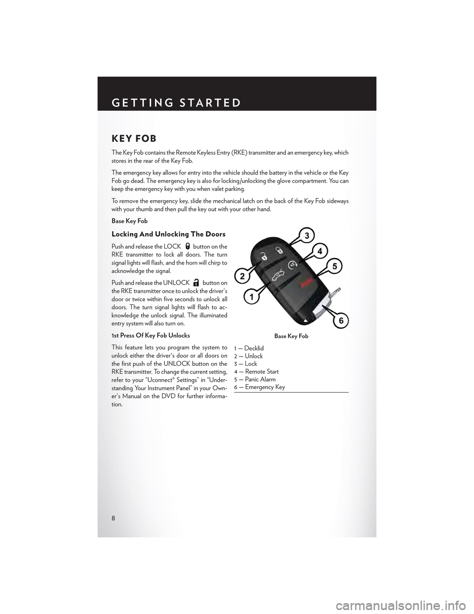
The Key Fob contains the Remote Keyless Entry (RKE) transmitter and an emergency key, which
stores in the rear of the Key Fob.
The emergency key allows for entry into the vehicle should the battery in the vehicle or the Key
Fob go dead. The emergency key is also for locking /unlocking the glove compartment. You can
keep the emergency key with you when valet parking.
To r e m o v e t h e e m e r g e n c y k e y , s l i d e t h e m e c h a n i c a l l a t c h o n t h e b a c k o f t h e K e y F o b s i d e w a y s
with your thumb and then pull the key out with your other hand.
Base Key Fob
Locking And Unlocking The Doors
Push and release the LOCKbutton on the
RKE transmitter to lock all doors. The turn
signal lights will flash, and the horn will chirp to
acknowledge the signal.
Push and release the UNLOCKbutton on
the RKE transmitter once to unlock the driver's
door or twice within five seconds to unlock all
doors. The turn signal lights will flash to ac-
knowledge the unlock signal. The illuminated
entry system will also turn on.
1st Press Of Key Fob Unlocks
This feature lets you program the system to
unlock either the driver's door or all doors on
the first push of the UNLOCK button on the
RKE transmitter. To change the current setting,
refer to your “Uconnect® Settings” in “Under-
standing Your Instrument Panel” in your Own-
er's Manual on the DVD for further informa-
tion.
Base Key Fob
1 — Decklid2 — Unlock3 — Lock4 — Remote Start5 — Panic Alarm6 — Emergency Key
GETTING STARTED
8
Page 16 of 180
VEHICLE SECURITY ALARM
The Vehicle Security Alarm monitors the vehicle doors for unauthorized entry and the Keyless
Enter-N-Go™ START/STOP button for unauthorized operation. While the Vehicle Security
Alarm is armed, interior switches for door locks and decklid release are disabled. If something
triggers the alarm, the Vehicle Security Alarm will provide the following audible and visible
signals: the horn will pulse, the park lamps and/or turn signals will flash, and the Vehicle Security
Light in the instrument cluster will flash.
To A r m :
•PushtheKeylessEnter-N-Go™START/STOPbuttonuntiltheDriverInformationDisplay
(DID) indicates that the vehicle ignition is “OFF.” Push the power door lock switch while the
door is open, push the Key Fob LOCK button, or with one of the Key Fobs located outside the
vehicle and within 5 ft (1.5 m) of the driver's and passenger front door handles, push the
Keyless Enter-N-Go™ LOCK button located on the door handle.
NOTE:
After pushing the Keyless Enter-N-Go™ LOCK button, you must wait two seconds before youcan lock or unlock the vehicle via the door handle.
To D i s a r m :
•PushtheKeyFobUNLOCKbuttonorwithoneoftheKeyFobslocatedoutsidethevehicle
and within 5 ft (1.5 m) of the driver's and passenger front door handles, grab the Keyless
Enter-N-Go™ door handle and enter the vehicle, then push the Keyless Enter-N-Go™ START/
STOP button (requires at least one valid Key Fob in the vehicle).
SEAT BELT SYSTEMS
Lap/Shoulder Belts
•Allseatingpositionsinyourvehicleareequippedwithlap/shoulderbelts.
•Besureeveryoneinyourvehicleisinaseatandusingaseatbeltproperly.
•Positionthelapbeltsothatitissnugandlieslowacrossyourhips,belowyourabdomen.To
remove slack in the lap belt portion, pull up on the shoulder belt. To loosen the lap belt if it is
too tight, tilt the latch plate and pull on the lap belt. A snug seat belt reduces the risk of sliding
under the seat belt in a collision.
• Position the shoulder belt across the shoulder and chest with minimal, if any slack so that it is
comfortable and not resting on your neck. The retractor will withdraw any slack in the shoulder
belt.
Seat Belt Pretensioner
•Thefrontseatbeltsystemisequippedwithpretensioningdevicesthataredesignedtoremove
slack from the seat belt in the event of a collision.
•Adeployedpretensioneroradeployedairbagmustbereplacedimmediately.
GETTING STARTED
14
Page 32 of 180
TILT/TELESCOPING STEERING COLUMN
Manual Tilt/Telescoping Steering Column
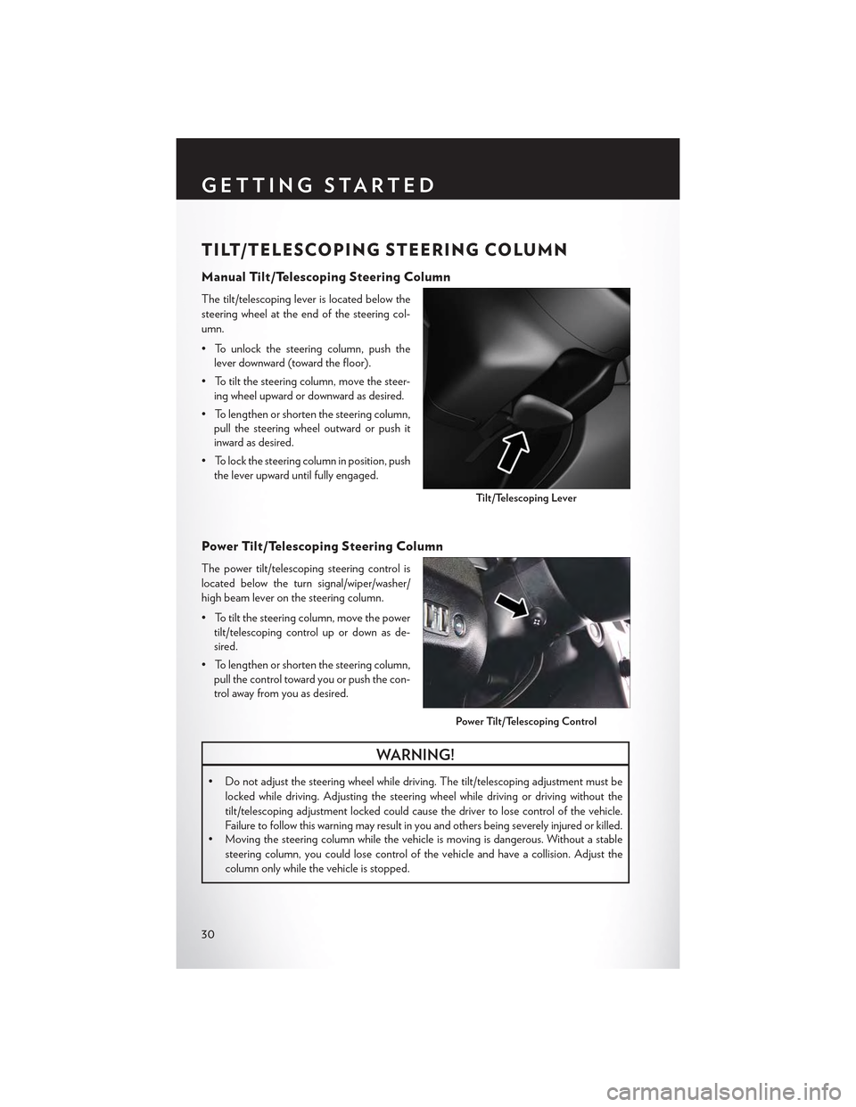
The tilt/telescoping lever is located below the
steering wheel at the end of the steering col-
umn.
• To unlock the steering column, push the
lever downward (toward the floor).
•Totiltthesteeringcolumn,movethesteer-
ing wheel upward or downward as desired.
• To lengthen or shorten the steering column,
pull the steering wheel outward or push it
inward as desired.
• To lock the steering column in position, push
the lever upward until fully engaged.
Power Tilt/Telescoping Steering Column
The power tilt/telescoping steering control is
located below the turn signal/wiper/washer/
high beam lever on the steering column.
•Totiltthesteeringcolumn,movethepower
tilt/telescoping control up or down as de-
sired.
• To lengthen or shorten the steering column,
pull the control toward you or push the con-
trol away from you as desired.
WARNING!
• Do not adjust the steering wheel while driving. The tilt/telescoping adjustment must be
locked while driving. Adjusting the steering wheel while driving or driving without the
tilt/telescoping adjustment locked could cause the driver to lose control of the vehicle.
Failure to follow this warning may result in you and others being severely injured or killed.•Movingthesteeringcolumnwhilethevehicleismovingisdangerous.Withoutastable
steering column, you could lose control of the vehicle and have a collision. Adjust the
column only while the vehicle is stopped.
Ti l t / Te l e s c o p i n g Le v e r
Power Tilt/Telescoping Control
GETTING STARTED
30
Page 34 of 180

TURN SIGNAL/WIPER/WASHER/HIGH BEAM
LEVER
Tu r n S i g n a l / L a n e C h a n g e A s s i s t
Ta p t h e l e v e r u p o r d o w n o n c e a n d t h e t u r n s i g n a l ( r i g h t o r l e f t ) w i l l f l a s h t h r e e t i m e s a n d
automatically turn off.
Front Wipers
Intermittent, Low And High Operation
Rotate the end of the lever to the first detent position for one of four intermittent settings, the
second detent for low wiper operation and the third detent for high wiper operation.
Mist
Rotate the end of the lever rearward when a single wipe is desired.
NOTE:
The mist feature does not activate the washer pump; therefore, no washer fluid will be sprayed on
the windshield. The wash function must be activated in order to spray the windshield with washer
fluid.
Washer Operation
Push the end of the lever inward and hold for as long as spray is desired.
Multifunction Lever
1 — Push For Washer2 — Rotate Downward For Mist3—PushLeverForHighBeams
OPERATING YOUR VEHICLE
32
Page 44 of 180
LANESENSE
The LaneSense system can be enabled and disabled with the LaneSense button, located on the
switch panel below the Uconnect® display.
• Push the LaneSense buttonto turn the system ON (LED turns off ).
The LaneSense system is operational at speeds above 37 mph (60 km/h) and below 112 mph(180 km/h). The LaneSense system uses a forward looking camera to detect lane markings andmeasure vehicle position within the lane boundaries.
When both lane markings are detected and the driver unintentionally drifts out of the lane (noturn signal applied), the LaneSense system provides a haptic warning in the form of torqueapplied to the steering wheel to prompt the driver to remain within the lane boundaries. If thedriver continues to unintentionally drift out of the lane, the LaneSense system provides a visualwarning through the Driver Information Display (DID) to prompt the driver to remain within thelane boundaries.
The driver may manually override the haptic warning by applying torque into the steering wheelat any time.
When only a single lane marking is detected and the driver unintentionally drifts across the lanemarking (no turn signal applied), the LaneSense system provides a visual warning through theDriver Information Display (DID) to prompt the driver to remain within the lane. When only asingle lane marking is detected, a haptic (torque) warning will not be provided.
Refer to your Owner's Manual on the DVD for further details.
NOTE:
When operating conditions have been met, the LaneSense system will monitor if the driver’shands are on the steering wheel and provides an audible warning to the driver when the driver’shands are not detected on the steering wheel. The system will cancel if the driver does not returntheir hands to the wheel.
PA R K V I E W ® R E A R B AC K- U P C A M E R A
Yo u c a n s e e a n o n - s c r e e n i m a g e o f t h e r e a r o f y o u r v e h i c l e w h e n e v e r t h e t r a n s m i s s i o n i s s h i f t e dinto REVERSE. The ParkView® Rear Back-Up Camera image will be displayed on the radiodisplay screen, located on the center stack of the instrument panel.
If the radio display screen appears foggy, clean the camera lens located on the rear of the vehicleabove the rear license plate.
Refer to “ParkView® Rear Back-Up Camera — If Equipped” in “Understanding The Features Of
Yo u r Ve h i c l e ” i n y o u r O w n e r ' s M a n u a l o n t h e D V D f o r f u r t h e r d e t a i l s .
WARNING!
Drivers must be careful when backing up; even when using the ParkView® Rear Back-Up
Camera. Always check carefully behind your vehicle, and be sure to check for pedestrians,
animals, other vehicles, obstructions, or blind spots before backing up. You must continue to
pay attention while backing up. Failure to do so can result in serious injury or death.
OPERATING YOUR VEHICLE
42
Page 63 of 180
Selling Your Vehicle
When you sell your vehicle, we recommend that you remove your Uconnect® Access Account
information from the vehicle. You can do this using the radio touchscreen in the vehicle or on the
Mopar Owner Connect website (moparownerconnect.com). Removing your account informa-
tion cancels your subscription and makes your vehicle factory-ready for a new owner/subscriber.
1. From your vehicle’s radio touchscreen, select “Uconnect® Store” from the Apps Menu.
2. Select “My Apps,” then “Settings.” Press “Remove Uconnect® Account.”
3. Enter your Uconnect® Security PIN, and select “Continue.”
For additional information on Uconnect®:
•U.S.residents-visitDriveUconnect.comorcall1-877-855-8400.
•CanadianResidents-visitDriveUconnect.caorcall,1-800-465-2001(English)or
1-800-387-9983 (French).
Built-In Features (Uconnect® 8.4A/8.4AN)
CAUTION!
•Ignoringtherearviewmirrorlightcouldmeanyoumaynothave9-1-1Callserviceif
needed. If the rearview mirror light is illuminated, have an authorized dealer service the
9-1-1 Call system immediately.
•TheOccupantRestraintController(ORC)turnsontheAirBagWarningLightonthe
instrument panel if a malfunction is detected in any part of the air bag system. If the Air
Bag Warning Light is illuminated, the air bag system may not be working properly and the
9-1-1 system may not be able to send a signal to a 9-1-1 operator. If the Air Bag Warning
Light is illuminated, have an authorized dealer service your vehicle immediately.
•Ifanyoneinthevehiclecouldbeindanger(e.g.,fireorsmokeisvisible,dangerousroad
conditions or location), do not wait for voice contact from a 9-1-1 operator. All occupants
should exit the vehicle immediately and move to a safe location.
•Donotaddanyaftermarketelectricalequipmenttothevehicle’selectricalsystem.This
may prevent your vehicle from sending a signal to initiate an emergency call. To avoid
interference that can cause the 9-1-1 Call system to fail, never add aftermarket equipment
(e.g., two-way mobile radio, CB radio, data recorder, etc.) to your vehicle’s electrical
system or modify the antennas on your vehicle. IF YOUR VEHICLE LOSES BATTERY
POWER FOR ANY REASON (INCLUDING DURING OR AFTER AN ACCI-
DENT), THE UCONNECT® FEATURES, APPS AND SERVICES, AMONG OTH-
ERS, WILL NOT OPERATE.
ELECTRONICS
61
Page 65 of 180
4.Yelp®—Customershavetheabilitytosearchfornearbydestinationsorapointofinterest
(POI) either by category or custom search by using keywords (for example, “Italian restau-
rant”). Searching can be done by either voice or by using the touchscreen keypad. Using the
touchscreen, launch Yelp® by selecting the “Apps” icon, press the “All Apps” tab, and then
press “Yelp.” Using voice recognition, push the Voice Command (VR) button on the steering
wheel and say “Launch Yelp®.”
5.Security Alarm Notification—TheSecurityAlarmNotificationfeaturenotifiesyouviaemail
or text (SMS) message when the vehicle’s factory-installed security alarm system has been
set-off. There are a number of reasons why your alarm may have been triggered, one of which
could be that your vehicle was stolen. If so, please see the details of the Stolen Vehicle
Assistance service below. When you register, Security Alarm Notification is automatically set
to send you an email at the mail address you provide should the alarm go off. You may also opt
to have a text message sent to your mobile device.
6.Stolen Vehicle Assistance—Ifyourvehicleisstolen,contactlocallawenforcementimme-
diately to file a stolen vehicle report. Once this report has been filed, Uconnect® care can help
locate your vehicle. The Uconnect® Care agent will ask for the stolen vehicle report number
issued by local law enforcement. Then, using GPS technology and the built-in wireless
connection within your vehicle, the Uconnect® Care agent will be able to locate the stolen
vehicle and work with law enforcement to help recover it. (Vehicle must be within the United
States, have network coverage and must be registered with Uconnect® Access with an active
subscription that includes the applicable feature).
7.WiFi Hotspot—WiFiHotspotison-demandWiFi3Gconnectivitythat'sbuilt-inandready
to go whenever you are. Once your vehicle is registered for Uconnect® Access, you can
purchase a Wifi Hotspot subscription at the Uconnect® Store. After you've made your
purchase, turn on your signal and connect your passengers devices. It's never been easier to
bring your home or office with you.
NOTE:
Yo u r v e h i c l e m u s t h a v e a w o r k i n g e l e c t r i c a l s y s t e m f o r a n y o f t h e i n v e h i c l e U c o n n e c t ® f e a t u r e s t o
operate.
Uconnect® Access Remote Features
If you own a compatible iPhone® or Android® powered device, the Uconnect® Access App allows
you to remotely lock or unlock your doors, start your engine or activate your horn and lights from
virtually anywhere (Vehicle must be within the United States and have network coverage). You
can download the App from Mopar Owner Connect or from the App Store (iPhone) or Google
Play store. Visit UconnectPhone.com to determine if your device is compatible. For Uconnect®
Phone customer support and to determine if your device is compatible.
U.S. residents - visit UconnectPhone.com or call 1-877-855-8400
ELECTRONICS
63
Page 69 of 180

Launch the Uconnect® Access App on your smartphone, and login with your username and
password that was set up during registration, (this is your moparownerconnect.com login).
Accept the Terms and Conditions.
• Ensure that Via Mobile data has been
turned on under “Settings” in the Uconnect®
Access App.
• A green indicator next to the words Via
Mobile will show when it is ready to provide
data to the radio (a blue indicator when data
is being sent). A red indicator means that it is
not ready to provide data.
•Onandroidphones,anorange/yellowindi-
cator signals the phone is connected to the
appropriate servers however, Bluetooth® is
turned off on their mobile phone.
Via Mobile Data Enabled
ELECTRONICS
67
Page 124 of 180
4. Continue to hold both buttons and observe the indicator light. The HomeLink® indicator will
flash slowly and then rapidly after HomeLink® has received the frequency signal from the
hand-held transmitter. Release both buttons after the indicator light changes from slow to
rapid.
5. At the garage door opener motor (in the garage), locate the “LEARN” or “TRAINING”
button. This can usually be found where the hanging antenna wire is attached to the garage
door opener motor. Firmly push and release the “LEARN” or “TRAINING” button.
NOTE:
Yo u h a v e 3 0 s e c o n d s i n w h i c h t o i n i t i a t e t h e n e x t s t e p a f t e r t h e L E A R N b u t t o n h a s b e e n p u s h e d .
6. Return to the vehicle and push the programmed HomeLink® button twice (holding the button
for two seconds each time). If the device is plugged in and activates, programming is
complete.
NOTE:
If the device does not activate, push the button a third time (for two seconds) to complete the
training.
7. To program the remaining two HomeLink® buttons, repeat each step for each remaining
button. DO NOT erase the channels.
Programming A Non-Rolling Code
NOTE:
For programming Garage Door Openers manufactured before 1995.
1. Turn the ignition switch to the ON/RUN position.
2. Place the hand-held transmitter 1 to 3 inches (3 to 8 cm) away from the HomeLink® button you
wish to program while keeping the HomeLink® indicator light in view.
3. Push and hold the HomeLink® button you want to program while you push and hold the
hand-held transmitter button.
4. Continue to hold both buttons and observe the indicator light. The HomeLink® indicator will
flash slowly and then rapidly after HomeLink® has received the frequency signal from the
hand-held transmitter. Release both buttons after the indicator light changes from slow to
rapid.
5. Push and hold the programmed HomeLink® button and observe the indicator light. If the
indicator light stays on constantly, programming is complete and the garage door (or device)
should activate when the HomeLink® button is pushed.
6. To program the two remaining HomeLink® buttons, repeat each step for each remaining
button. DO NOT erase the channels.
Using HomeLink®
To o p e r a t e , p u s h a n d r e l e a s e t h e p r o g r a m m e d H o m e L i n k ® b u t t o n . A c t i v a t i o n w i l l n o w o c c u r f o r
the programmed device (e.g., garage door opener, gate operator, security system, entry door
lock, home/office lighting, etc.). The hand-held transmitter of the device may also be used at any
time.
ELECTRONICS
122