CHRYSLER 300 2020 Manual PDF
Manufacturer: CHRYSLER, Model Year: 2020, Model line: 300, Model: CHRYSLER 300 2020Pages: 328, PDF Size: 14.28 MB
Page 71 of 328
GETTING TO KNOW YOUR VEHICLE69
Reprogramming A Single HomeLink® Button
(Canadian/Gate Operator)
To reprogram a channel that has been
previously trained, follow these steps:
1. Place the ignition in the ON/RUN position.
2. Press and hold the desired HomeLink®
button until the indicator light begins to
flash after 20 seconds. Do not release the
button.
3. Without releasing the button, proceed with “Canadian/Gate Operator Programming”
step 2 and follow all remaining steps.
USING HOMELINK®
To operate, push and release the programmed
HomeLink® button. Activation will now occur for
the programmed device (i.e. garage door
opener, gate operator, security system, entry
door lock, home/office lighting, etc.). The
hand-held transmitter of the device may also be
used at any time.
SECURITY
It is advised to erase all channels before you sell
or turn in your vehicle.
To do this, push and hold the two outside
buttons for 20 seconds until the orange
indicator flashes. Note that all channels will be
erased. Individual channels cannot be erased.
The HomeLink® Universal Transceiver is
disabled when the Vehicle Security Alarm is
active.
TROUBLESHOOTING TIPS
If you are having trouble programming
HomeLink®, here are some of the most
common solutions:
Replace the battery in the garage door
opener hand-held transmitter.
Push the LEARN button on the garage door
opener to complete the training for a rolling
code.
Did you unplug the device for programming
and remember to plug it back in? If you have any problems, or require assistance,
please call toll-free 1-800-355-3515 or, on the
Internet at HomeLink.com for information or
assistance.
WARNING!
Vehicle exhaust contains carbon monoxide,
a dangerous gas. Do not run your vehicle in
the garage while programming the trans -
ceiver. Exhaust gas can cause serious
injury or death.
Your motorized door or gate will open and
close while you are programming the
universal transceiver. Do not program the
transceiver if people, pets or other objects
are in the path of the door or gate. Only use
this transceiver with a garage door opener
that has a “stop and reverse” feature as
required by Federal safety standards. This
includes most garage door opener models
manufactured after 1982. Do not use a
garage door opener without these safety
features. Call toll-free 1-800-355-3515 or,
on the Internet at HomeLink.com for safety
information or assistance.
2
20_LX_OM_EN_USC_t.book Page 69
Page 72 of 328
70GETTING TO KNOW YOUR VEHICLE
GENERAL INFORMATION
The following regulatory statement applies to all
Radio Frequency (RF) devices equipped in this
vehicle:
This device complies with Part 15 of the FCC
Rules and with Innovation, Science and
Economic Development Canada license-exempt
RSS standard(s). Operation is subject to the
following two conditions:
1. This device may not cause harmful
interference, and
2. This device must accept any interference received, including interference that may
cause undesired operation.
Le présent appareil est conforme aux CNR
d`Innovation, Science and Economic
Development applicables aux appareils radio
exempts de licence. L'exploitation est autorisée
aux deux conditions suivantes:
1. l'appareil ne doit pas produire de brouillage, et
2. l'utilisateur de l'appareil doit accepter tout brouillage radioélectrique subi, même si le brouillage est susceptible d'en compro
-
mettre le fonctionnement.
La operación de este equipo está sujeta a las
siguientes dos condiciones:
1. es posible que este equipo o dispositivo no cause interferencia perjudicial y
2. este equipo o dispositivo debe aceptar cualquier interferencia, incluyendo la que
pueda causar su operación no deseada.
NOTE:
Changes or modifications not expressly
approved by the party responsible for compli -
ance could void the user’s authority to operate
the equipment.
INTERNAL EQUIPMENT
STORAGE
Glove Compartment
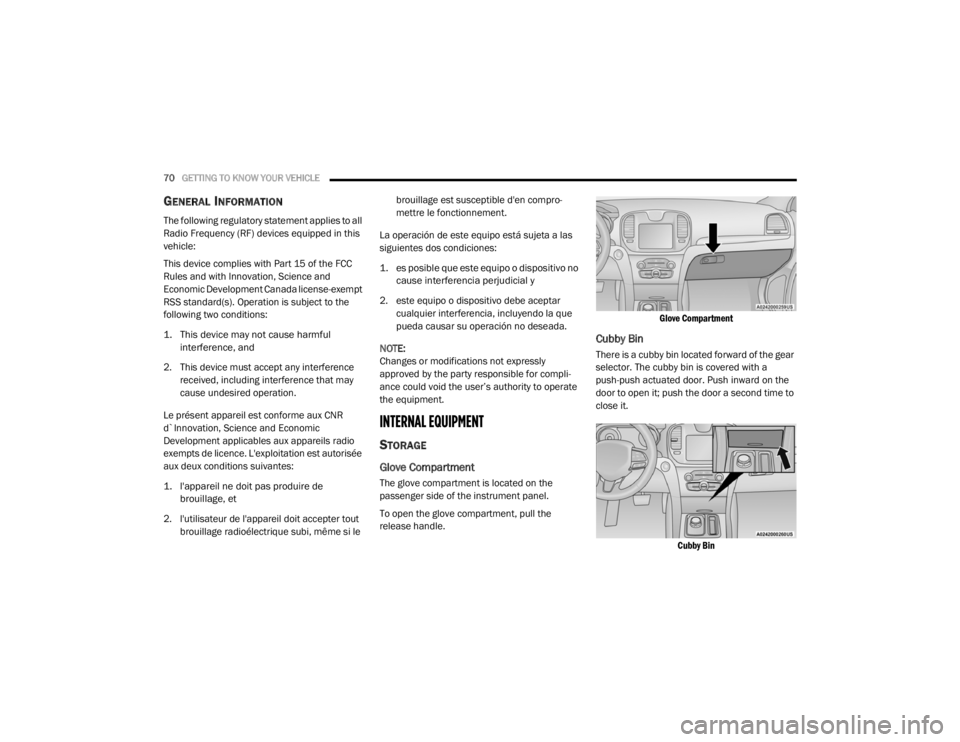
The glove compartment is located on the
passenger side of the instrument panel.
To open the glove compartment, pull the
release handle.
Glove Compartment
Cubby Bin
There is a cubby bin located forward of the gear
selector. The cubby bin is covered with a
push-push actuated door. Push inward on the
door to open it; push the door a second time to
close it.
Cubby Bin
20_LX_OM_EN_USC_t.book Page 70
Page 73 of 328
GETTING TO KNOW YOUR VEHICLE71
Console Features
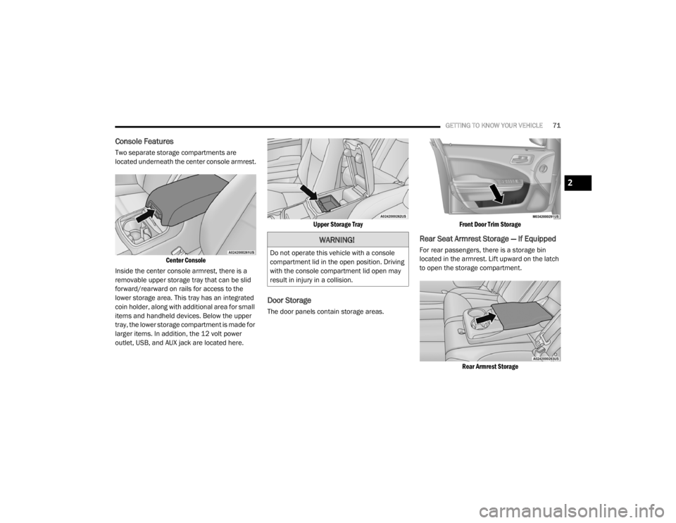
Two separate storage compartments are
located underneath the center console armrest.
Center Console
Inside the center console armrest, there is a
removable upper storage tray that can be slid
forward/rearward on rails for access to the
lower storage area. This tray has an integrated
coin holder, along with additional area for small
items and handheld devices. Below the upper
tray, the lower storage compartment is made for
larger items. In addition, the 12 volt power
outlet, USB, and AUX jack are located here.
Upper Storage Tray
Door Storage
The door panels contain storage areas.
Front Door Trim Storage
Rear Seat Armrest Storage — If Equipped
For rear passengers, there is a storage bin
located in the armrest. Lift upward on the latch
to open the storage compartment.
Rear Armrest Storage
WARNING!
Do not operate this vehicle with a console
compartment lid in the open position. Driving
with the console compartment lid open may
result in injury in a collision.
2
20_LX_OM_EN_USC_t.book Page 71
Page 74 of 328
72GETTING TO KNOW YOUR VEHICLE
CUPHOLDERS
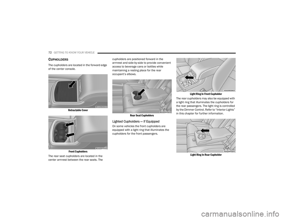
The cupholders are located in the forward edge
of the center console.
Retractable CoverFront Cupholders
The rear seat cupholders are located in the
center armrest between the rear seats. The cupholders are positioned forward in the
armrest and side-by-side to provide convenient
access to beverage cans or bottles while
maintaining a resting place for the rear
occupant’s elbows.
Rear Seat Cupholders
Lighted Cupholders — If Equipped
On some vehicles the front cupholders are
equipped with a light ring that illuminates the
cupholders for the front passengers.
Light Ring In Front Cupholder
The rear cupholders may also be equipped with
a light ring that illuminates the cupholders for
the rear passengers. The light ring is controlled
by the Dimmer Control. Refer to “Interior Lights”
in this chapter for further information.
Light Ring In Rear Cupholder
20_LX_OM_EN_USC_t.book Page 72
Page 75 of 328
GETTING TO KNOW YOUR VEHICLE73
Heated And Cooled Cupholders — If
Equipped
Your vehicle may be equipped with heated and
cooled cupholders. The cupholders are
designed to help keep warm beverages warm
and cool beverages cool.
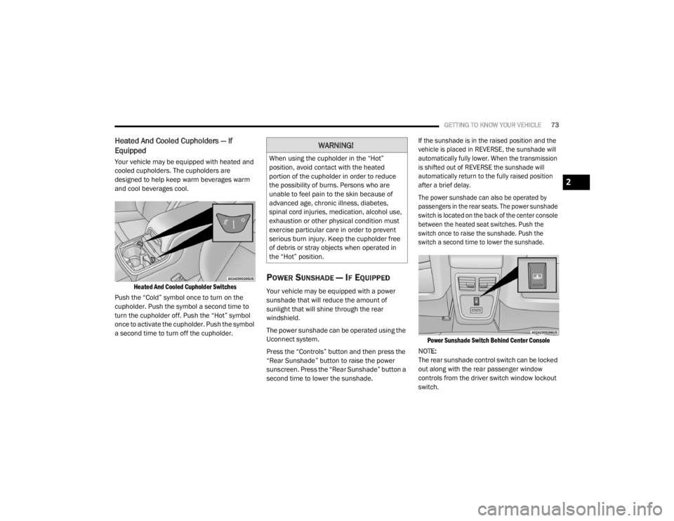
Heated And Cooled Cupholder Switches
Push the “Cold” symbol once to turn on the
cupholder. Push the symbol a second time to
turn the cupholder off. Push the “Hot” symbol
once to activate the cupholder. Push the symbol
a second time to turn off the cupholder.
POWER SUNSHADE — IF EQUIPPED
Your vehicle may be equipped with a power
sunshade that will reduce the amount of
sunlight that will shine through the rear
windshield.
The power sunshade can be operated using the
Uconnect system.
Press the “Controls” button and then press the
“Rear Sunshade” button to raise the power
sunscreen. Press the “Rear Sunshade” button a
second time to lower the sunshade.
If the sunshade is in the raised position and the
vehicle is placed in REVERSE, the sunshade will
automatically fully lower. When the transmission
is shifted out of REVERSE the sunshade will
automatically return to the fully raised position
after a brief delay.
The power sunshade can also be operated by
passengers in the rear seats. The power sunshade
switch is located on the back of the center console
between the heated seat switches. Push the
switch once to raise the sunshade. Push the
switch a second time to lower the sunshade.
Power Sunshade Switch Behind Center Console
NOTE:
The rear sunshade control switch can be locked
out along with the rear passenger window
controls from the driver switch window lockout
switch.
WARNING!
When using the cupholder in the “Hot”
position, avoid contact with the heated
portion of the cupholder in order to reduce
the possibility of burns. Persons who are
unable to feel pain to the skin because of
advanced age, chronic illness, diabetes,
spinal cord injuries, medication, alcohol use,
exhaustion or other physical condition must
exercise particular care in order to prevent
serious burn injury. Keep the cupholder free
of debris or stray objects when operated in
the “Hot” position.
2
20_LX_OM_EN_USC_t.book Page 73
Page 76 of 328
74GETTING TO KNOW YOUR VEHICLE
ELECTRICAL POWER OUTLETS
Your vehicle is equipped with one 12 Volt
(13 Amp) power outlet on the instrument panel
and one 12 Volt (13 Amp) power outlet in the
center console that can be used to power
cellular phones, small electronics and other low
powered electrical accessories. The power
outlets are labeled with either a “key” or a
“battery” symbol to indicate how the outlet is
powered. Power outlets labeled with a “key” are
powered when the ignition switch is in the ACC
or ON/RUN position, while the outlets labeled
with a “battery” are connected directly to the
battery and powered at all times.
NOTE:
All accessories connected to the “battery”
powered outlets should be removed or turned
off when the vehicle is not in use to protect the
battery against discharge.
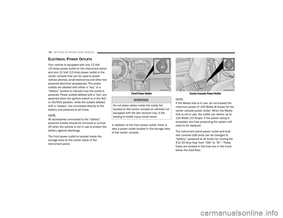
The front power outlet is located inside the
storage area on the center stack of the
instrument panel.
Front Power Outlet
In addition to the front power outlet, there is
also a power outlet located in the storage area
of the center console.
Center Console Power Outlet
NOTE:
If the Media Hub is in use, do not exceed the
maximum power of 100 Watts (8 Amps) for the
center console power outlet. When the Media
Hub is not in use, the outlet can deliver up to
120 Watts (10 Amps). If the power rating is
exceeded, the fuse protecting the system will
need to be replaced.
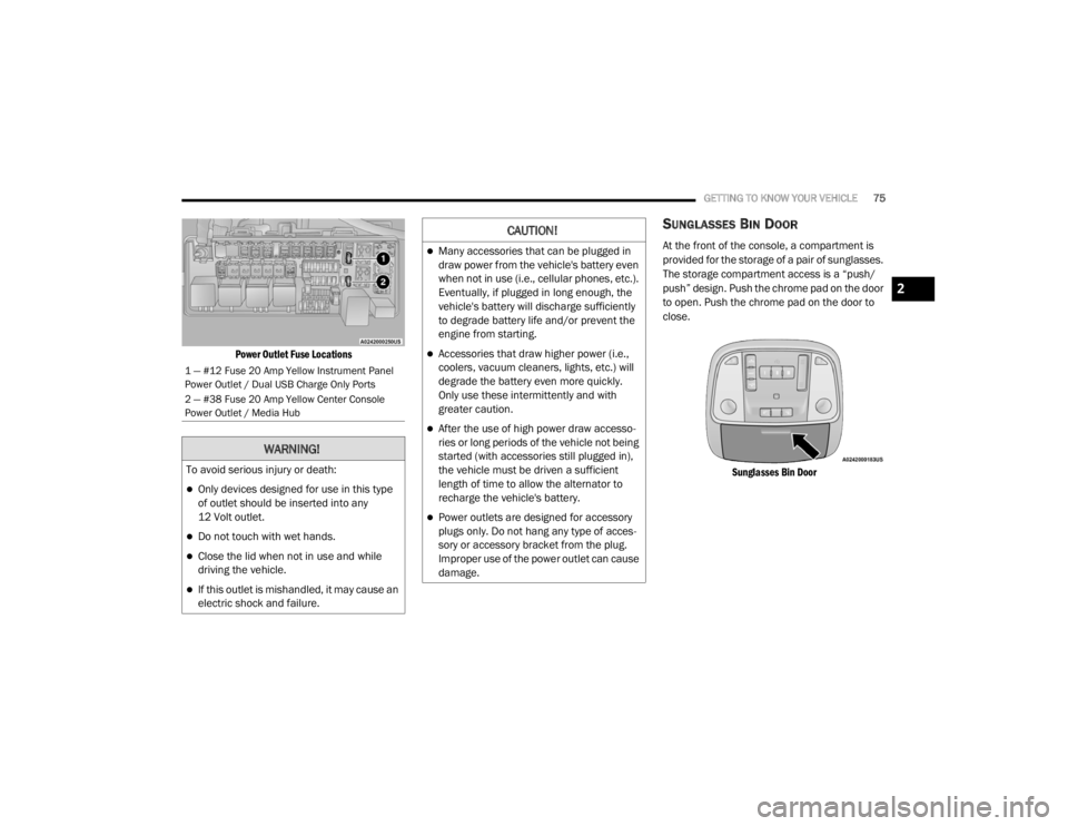
The instrument panel power outlet and dual
rear console USB ports can be changed to
“battery” (powered at all times) by moving the
#12 20 Amp fuse from “IGN” to “B+”. These
fuses are located in the fuse box in the trunk,
below the load floor.
WARNING!
Do not place ashes inside the cubby bin
located on the center console on vehicles not
equipped with the ash receiver tray. A fire
leading to bodily injury could result.
20_LX_OM_EN_USC_t.book Page 74
Page 77 of 328
GETTING TO KNOW YOUR VEHICLE75
Power Outlet Fuse Locations
SUNGLASSES BIN DOOR
At the front of the console, a compartment is
provided for the storage of a pair of sunglasses.
The storage compartment access is a “push/
push” design. Push the chrome pad on the door
to open. Push the chrome pad on the door to
close.
Sunglasses Bin Door
1 — #12 Fuse 20 Amp Yellow Instrument Panel
Power Outlet / Dual USB Charge Only Ports
2 — #38 Fuse 20 Amp Yellow Center Console
Power Outlet / Media Hub
WARNING!
To avoid serious injury or death:
Only devices designed for use in this type
of outlet should be inserted into any
12 Volt outlet.
Do not touch with wet hands.
Close the lid when not in use and while
driving the vehicle.
If this outlet is mishandled, it may cause an
electric shock and failure.
CAUTION!
Many accessories that can be plugged in
draw power from the vehicle's battery even
when not in use (i.e., cellular phones, etc.).
Eventually, if plugged in long enough, the
vehicle's battery will discharge sufficiently
to degrade battery life and/or prevent the
engine from starting.
Accessories that draw higher power (i.e.,
coolers, vacuum cleaners, lights, etc.) will
degrade the battery even more quickly.
Only use these intermittently and with
greater caution.
After the use of high power draw accesso -
ries or long periods of the vehicle not being
started (with accessories still plugged in),
the vehicle must be driven a sufficient
length of time to allow the alternator to
recharge the vehicle's battery.
Power outlets are designed for accessory
plugs only. Do not hang any type of acces -
sory or accessory bracket from the plug.
Improper use of the power outlet can cause
damage.
2
20_LX_OM_EN_USC_t.book Page 75
Page 78 of 328
76
GETTING TO KNOW YOUR INSTRUMENT PANEL
INSTRUMENT CLUSTER
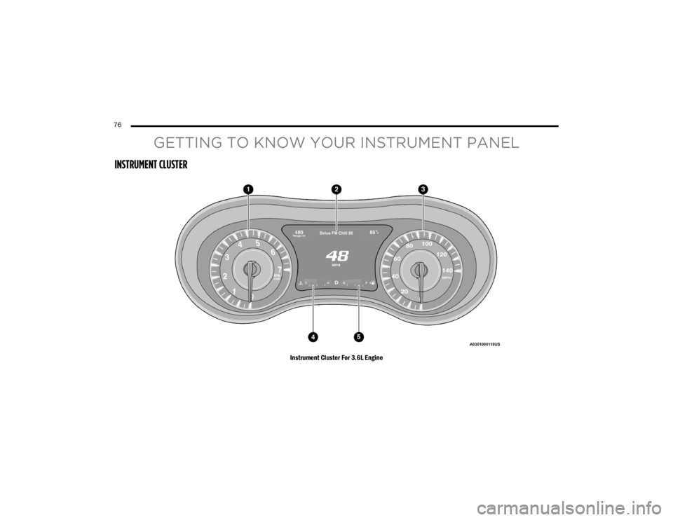
Instrument Cluster For 3.6L Engine
20_LX_OM_EN_USC_t.book Page 76
Page 79 of 328
GETTING TO KNOW YOUR INSTRUMENT PANEL77
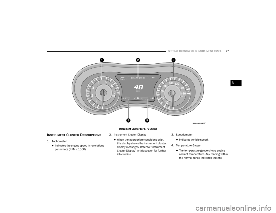
Instrument Cluster For 5.7L Engine
INSTRUMENT CLUSTER DESCRIPTIONS
1. Tachometer
Indicates the engine speed in revolutions
per minute (RPM x 1000).2. Instrument Cluster Display
When the appropriate conditions exist,
this display shows the instrument cluster
display messages. Refer to “Instrument
Cluster Display” in this section for further
information.3. SpeedometerIndicates vehicle speed.
4. Temperature Gauge
The temperature gauge shows engine
coolant temperature. Any reading within
the normal range indicates that the
3
20_LX_OM_EN_USC_t.book Page 77
Page 80 of 328
78GETTING TO KNOW YOUR INSTRUMENT PANEL
engine cooling system is operating satis-
factorily.
The gauge pointer will likely indicate a
higher temperature when driving in hot
weather, up mountain grades, or when
towing a trailer. It should not be allowed
to exceed the upper limits of the normal
operating range. 5. Fuel Gauge
The pointer shows the level of fuel in the
fuel tank when the Keyless Push Button
Ignition is in the ON/RUN position.
The fuel pump symbol points
to the side of the vehicle where
the fuel door is located.
For further information refer to “Refueling
The Vehicle” in “Starting And Operating.”
NOTE:
The warning / indicator Lights will briefly illumi -
nate for a bulb check when the ignition is first
cycled.
INSTRUMENT CLUSTER DISPLAY
Your vehicle is equipped with an instrument
cluster display, which offers useful information
to the driver. With the ignition in the OFF mode,
opening/closing of a door will activate the
display for viewing, and display the total miles,
or kilometers, in the odometer. Your instrument
cluster display is designed to display important
information about your vehicle’s systems and
features. Using a driver interactive display
located on the instrument panel, your
instrument cluster display can show you how systems are working and give you warnings
when they are not. The steering wheel mounted
controls allow you to scroll through the main
menus and submenus. You can access the
specific information you want and make
selections and adjustments.
LOCATION AND CONTROLS
The instrument cluster display features an
interactive display which is located in the
instrument cluster.
This system conveniently allows the driver to
select a variety of useful information by pushing
the arrow buttons located on the left side of the
steering wheel. The instrument cluster display
menu items consist of the following:
Speedometer
Vehicle Info
Driver Assist — If Equipped
Fuel Economy
Trip
Audio
Messages
Screen Setup
WARNING!
A hot engine cooling system is dangerous.
You or others could be badly burned by steam
or boiling coolant. You may want to call an
authorized dealer for service if your vehicle
overheats.
CAUTION!
Driving with a hot engine cooling system
could damage your vehicle. If the
temperature gauge reads “H,” pull over and
stop the vehicle. Idle the vehicle with the air
conditioner turned off until the pointer drops
back into the normal range. If the pointer
remains on the “H,” turn the engine off
immediately and call an authorized dealer for
service.
20_LX_OM_EN_USC_t.book Page 78