technical specifications CHRYSLER 300 2020 Owners Manual
[x] Cancel search | Manufacturer: CHRYSLER, Model Year: 2020, Model line: 300, Model: CHRYSLER 300 2020Pages: 328, PDF Size: 14.28 MB
Page 3 of 328
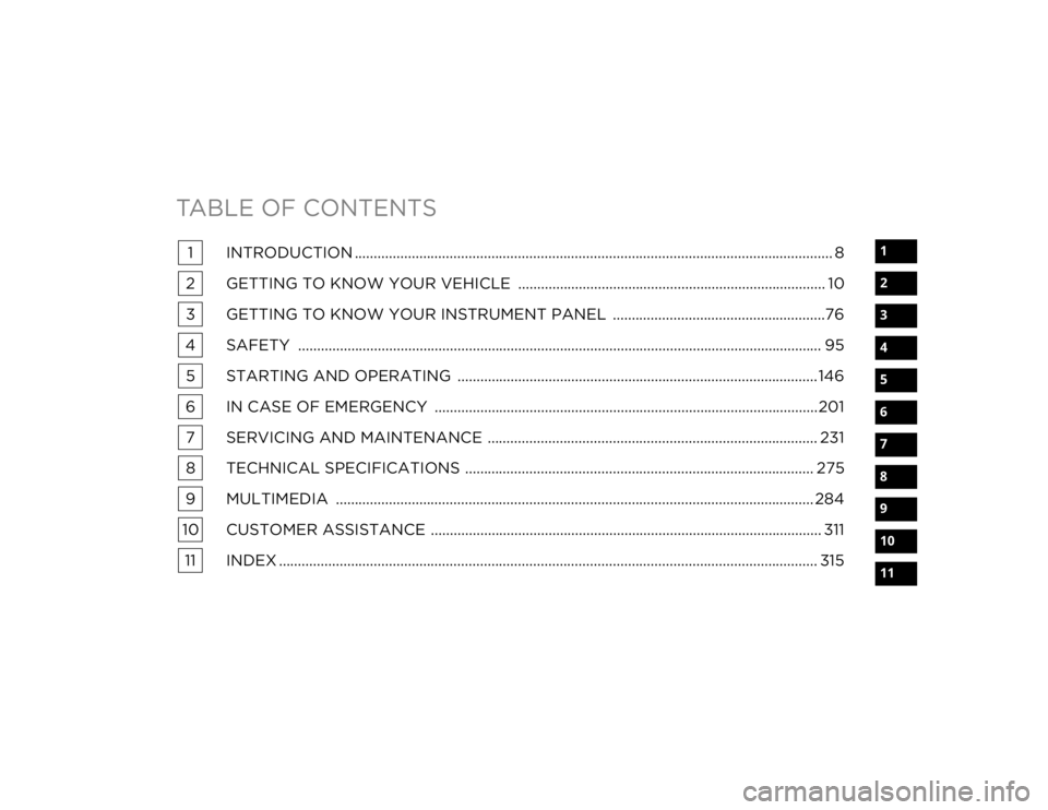
TABLE OF CONTENTS
1
2
3
4
5
6
7
8
9
10
11
1 INTRODUCTION .............................................................................................................................. 8
2 GETTING TO KNOW YOUR VEHICLE ................................................................................. 10
3 GETTING TO KNOW YOUR INSTRUMENT PANEL ........................................................76
4 SAFETY .......................................................................................................................................... 95 5 STARTING AND OPERATING ............................................................................................... 146
6 IN CASE OF EMERGENCY ..................................................................................................... 201 7 SERVICING AND MAINTENANCE ....................................................................................... 231
8 TECHNICAL SPECIFICATIONS ............................................................................................ 275
9 MULTIMEDIA .............................................................................................................................. 284
10 CUSTOMER ASSISTANCE ....................................................................................................... 311 11 INDEX .............................................................................................................................................. 315
20_LX_OM_EN_USC_t.book Page 1
Page 8 of 328
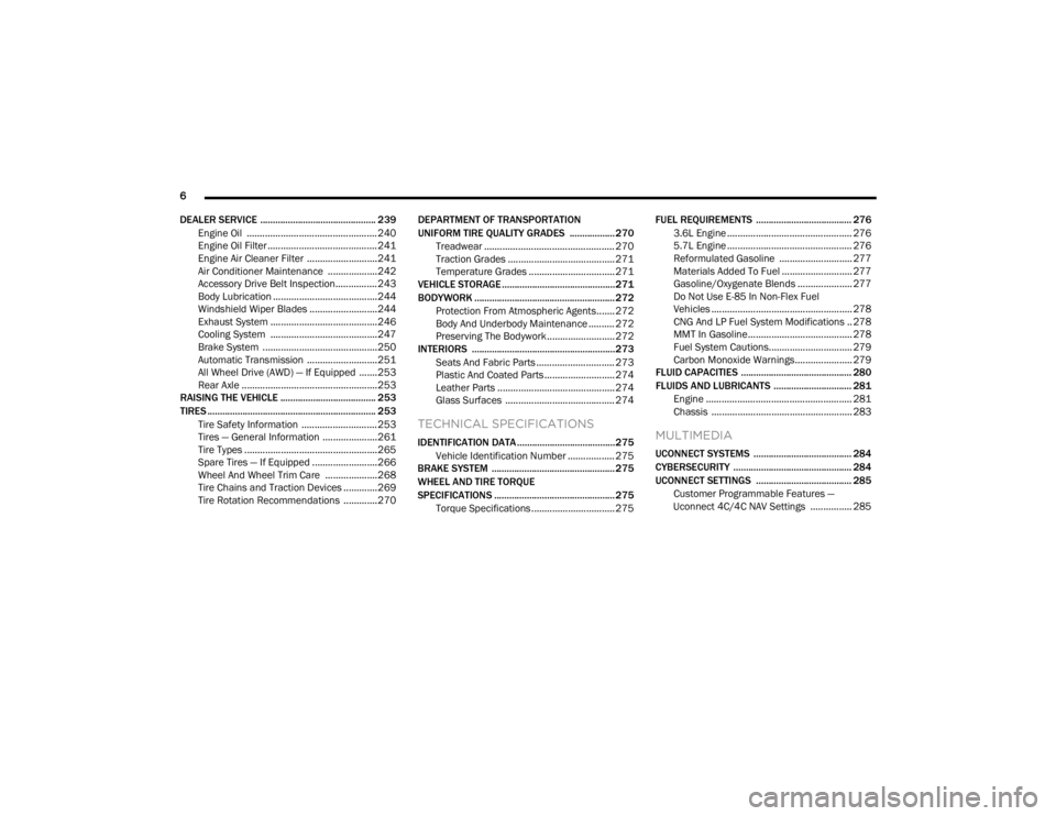
6
DEALER SERVICE .............................................. 239 Engine Oil .................................................. 240Engine Oil Filter ..........................................241Engine Air Cleaner Filter ...........................241
Air Conditioner Maintenance ...................242Accessory Drive Belt Inspection................243Body Lubrication ........................................244
Windshield Wiper Blades ..........................244
Exhaust System .........................................246
Cooling System .........................................247
Brake System ............................................250
Automatic Transmission ...........................251
All Wheel Drive (AWD) — If Equipped .......253
Rear Axle ....................................................253
RAISING THE VEHICLE ...................................... 253
TIRES ................................................................... 253
Tire Safety Information .............................253Tires — General Information .....................261Tire Types ...................................................265
Spare Tires — If Equipped .........................266
Wheel And Wheel Trim Care ....................268
Tire Chains and Traction Devices .............269
Tire Rotation Recommendations .............270 DEPARTMENT OF TRANSPORTATION
UNIFORM TIRE QUALITY GRADES .................. 270
Treadwear .................................................. 270
Traction Grades ......................................... 271
Temperature Grades ................................. 271
VEHICLE STORAGE .............................................271
BODYWORK ........................................................ 272
Protection From Atmospheric Agents....... 272
Body And Underbody Maintenance .......... 272Preserving The Bodywork .......................... 272
INTERIORS ......................................................... 273
Seats And Fabric Parts .............................. 273
Plastic And Coated Parts ........................... 274
Leather Parts ............................................. 274
Glass Surfaces .......................................... 274
TECHNICAL SPECIFICATIONS
IDENTIFICATION DATA .......................................275Vehicle Identification Number .................. 275
BRAKE SYSTEM ................................................. 275
WHEEL AND TIRE TORQUE
SPECIFICATIONS ................................................ 275
Torque Specifications ................................ 275 FUEL REQUIREMENTS ...................................... 276
3.6L Engine ................................................ 276
5.7L Engine ................................................ 276
Reformulated Gasoline ............................ 277Materials Added To Fuel ........................... 277
Gasoline/Oxygenate Blends ..................... 277
Do Not Use E-85 In Non-Flex Fuel
Vehicles ...................................................... 278 CNG And LP Fuel System Modifications .. 278MMT In Gasoline........................................ 278
Fuel System Cautions................................ 279
Carbon Monoxide Warnings...................... 279
FLUID CAPACITIES ............................................ 280
FLUIDS AND LUBRICANTS ............................... 281
Engine ........................................................ 281
Chassis ...................................................... 283MULTIMEDIA
UCONNECT SYSTEMS ....................................... 284
CYBERSECURITY ............................................... 284
UCONNECT SETTINGS ...................................... 285 Customer Programmable Features —
Uconnect 4C/4C NAV Settings ................ 285
20_LX_OM_EN_USC_t.book Page 6
Page 152 of 328
150STARTING AND OPERATING
ENGINE BREAK-IN RECOMMENDATIONS
A long break-in period is not required for the
drivetrain (engine, transmission, clutch, and
rear axle) in your new vehicle.
Drive moderately during the first 300 miles
(500 km). After the initial 60 miles (100 km),
speeds up to 50 or 55 mph (80 or 90 km/h) are
desirable.
While cruising, brief full-throttle acceleration
within the limits of local traffic laws contributes
to a good break-in. However, wide-open throttle
acceleration in low gear can be detrimental and
should be avoided.
The engine oil, transmission fluid, and axle
lubricant installed at the factory are high-quality
and energy-conserving. Oil, fluid, and lubricant
changes should be consistent with anticipated
climate and conditions under which vehicle
operations will occur. For the recommended
viscosity and quality grades, refer to “Fluids And
Lubricants” in “Technical Specifications”. NOTE:
A new engine may consume some oil during its
first few thousand miles (kilometers) of opera
-
tion. This should be considered a normal part of
the break-in and not interpreted as an indica -
tion of difficulty. Please check your oil level with
the engine oil indicator often during the break in
period. Add oil as required.
PARKING BRAKE
Before leaving the vehicle, make sure that the
parking brake is fully applied and place the gear
selector in the PARK position.
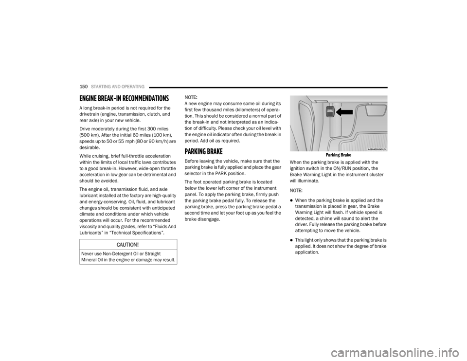
The foot operated parking brake is located
below the lower left corner of the instrument
panel. To apply the parking brake, firmly push
the parking brake pedal fully. To release the
parking brake, press the parking brake pedal a
second time and let your foot up as you feel the
brake disengage.
Parking Brake
When the parking brake is applied with the
ignition switch in the ON/RUN position, the
Brake Warning Light in the instrument cluster
will illuminate.
NOTE:
When the parking brake is applied and the
transmission is placed in gear, the Brake
Warning Light will flash. If vehicle speed is
detected, a chime will sound to alert the
driver. Fully release the parking brake before
attempting to move the vehicle.
This light only shows that the parking brake is
applied. It does not show the degree of brake
application.CAUTION!
Never use Non-Detergent Oil or Straight
Mineral Oil in the engine or damage may result.
20_LX_OM_EN_USC_t.book Page 150
Page 223 of 328

IN CASE OF EMERGENCY221
6. Remove the lug nuts and tire.
7. Mount the spare tire.
Mounting Spare Tire
NOTE:
For vehicles so equipped, do not attempt to
install a center cap or wheel cover on the
compact spare.
Refer to “Compact Spare Tire” and to
“Limited-Use Spare” under “Tires” in
“Servicing And Maintenance” for additional
warnings, cautions, and information about
the spare tire, its use, and operation.
8. Install the lug nuts with the cone shaped end of the lug nut toward the wheel. Lightly
tighten the lug nuts.
9. Lower the vehicle to the ground by turning the jack handle counterclockwise. 10. Finish tightening the lug nuts. Push down on
the wrench while at the end of the handle
for increased leverage. Tighten the lug nuts
in a star pattern until each nut has been
tightened twice. For the correct lug nut
torque, refer to “Wheel And Tire Torque
Specifications” in “Technical Specifi -
cations”. If in doubt about the correct
tightness, have them checked with a torque
wrench by an authorized dealer or at a
service station.
11. Stow the jack, tools and flat tire. Make sure the base of the jack faces the front of the
vehicle before tightening down the fastener.
WARNING!
Raising the vehicle higher than necessary can
make the vehicle less stable. It could slip off
the jack and hurt someone near it. Raise the
vehicle only enough to remove the tire.
CAUTION!
Be sure to mount the spare tire with the valve
stem facing outward. The vehicle could be
damaged if the spare tire is mounted
incorrectly.
WARNING!
To avoid the risk of forcing the vehicle off the
jack, do not tighten the wheel nuts fully until
the vehicle has been lowered. Failure to
follow this warning may result in serious
injury.WARNING!
A loose tire or jack thrown forward in a
collision or hard stop could endanger the
occupants of the vehicle. Always stow the jack
parts and the spare tire in the places
provided. Have the deflated (flat) tire repaired
or replaced immediately.
6
20_LX_OM_EN_USC_t.book Page 221
Page 224 of 328
222IN CASE OF EMERGENCY
(Continued)
ROAD TIRE INSTALLATION
1. Mount the road tire on the axle.
2. Install the remaining lug nuts with the cone shaped end of the nut toward the wheel.
Lightly tighten the lug nuts.
3. Lower the vehicle to the ground by turning the jack handle counterclockwise.
4. Refer to “Wheel And Tire Torque Specifi -
cations” in “Technical Specifications” for
proper lug nut torque.
5. After 25 miles (40 km), check the lug nut torque with a torque wrench to ensure that
all lug nuts are properly seated against the
wheel.
JUMP STARTING
If your vehicle has a discharged battery, it can
be jump started using a set of jumper cables
and a battery in another vehicle, or by using a
portable battery booster pack. Jump starting
can be dangerous if done improperly, so please
follow the procedures in this section carefully.
NOTE:
When using a portable battery booster pack,
follow the manufacturer's operating instruc -
tions and precautions.
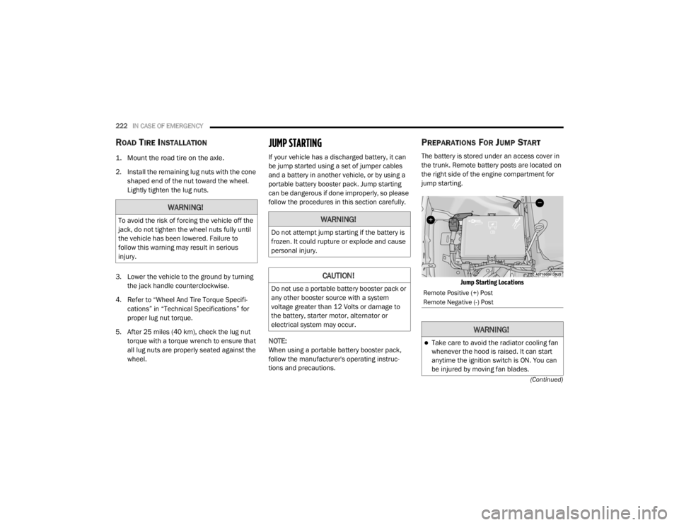
PREPARATIONS FOR JUMP START
The battery is stored under an access cover in
the trunk. Remote battery posts are located on
the right side of the engine compartment for
jump starting.
Jump Starting Locations
WARNING!
To avoid the risk of forcing the vehicle off the
jack, do not tighten the wheel nuts fully until
the vehicle has been lowered. Failure to
follow this warning may result in serious
injury.WARNING!
Do not attempt jump starting if the battery is
frozen. It could rupture or explode and cause
personal injury.
CAUTION!
Do not use a portable battery booster pack or
any other booster source with a system
voltage greater than 12 Volts or damage to
the battery, starter motor, alternator or
electrical system may occur.Remote Positive (+) Post
Remote Negative (-) Post
WARNING!
Take care to avoid the radiator cooling fan
whenever the hood is raised. It can start
anytime the ignition switch is ON. You can
be injured by moving fan blades.
20_LX_OM_EN_USC_t.book Page 222
Page 250 of 328
248SERVICING AND MAINTENANCE
be drained, flushed, and refilled with fresh
OAT coolant (conforming to MS.90032) by an
authorized dealer. Check the front of the
radiator for any accumulation of bugs, leaves,
etc. If dirty, clean by gently spraying water from
a garden hose vertically down the face of the
condenser.
Check the coolant recovery bottle tubing for
brittle rubber, cracking, tears, cuts, and
tightness of the connection at the bottle and
radiator. Inspect the entire system for leaks. DO
NOT REMOVE THE COOLANT PRESSURE CAP
WHEN THE COOLING SYSTEM IS HOT.
Cooling System — Drain, Flush And Refill
NOTE:
Some vehicles require special tools to add
coolant properly. Failure to fill these systems
properly could lead to severe internal engine
damage. If any coolant is needed to be added to
the system please contact an authorized dealer.
If the engine coolant (antifreeze) is dirty or
contains visible sediment, have an authorized
dealer clean and flush with OAT coolant
(antifreeze) (conforming to MS.90032).
Refer to the “Maintenance Plan” in this section
for the proper maintenance intervals.
Selection Of Coolant
Refer to “Fluids And Lubricants” in “Technical
Specifications” for further information.
NOTE:
Mixing of engine coolant (antifreeze) other
than specified Organic Additive Technology
(OAT) engine coolant (antifreeze), may result
in engine damage and may decrease corro -
sion protection. Organic Additive Technology
(OAT) engine coolant is different and should
not be mixed with Hybrid Organic Additive
Technology (HOAT) engine coolant (anti -
freeze) or any “globally compatible” coolant
(antifreeze). If a non-OAT engine coolant
(antifreeze) is introduced into the cooling
system in an emergency, the cooling system
will need to be drained, flushed, and refilled
with fresh OAT coolant (conforming to
MS.90032), by an authorized dealer as soon
as possible.
Do not use water alone or alcohol-based
engine coolant (antifreeze) products. Do not
use additional rust inhibitors or antirust prod -
ucts, as they may not be compatible with the
radiator engine coolant and may plug the
radiator.
This vehicle has not been designed for use
with propylene glycol-based engine coolant
(antifreeze). Use of propylene glycol-based
engine coolant (antifreeze) is not recom -
mended.
Some vehicles require special tools to add
coolant properly. Failure to fill these systems
properly could lead to severe internal engine
damage. If any coolant is needed to be added
to the system please contact an authorized
dealer.
Adding Coolant
Your vehicle has been built with an improved
engine coolant (OAT coolant conforming to
MS.90032) that allows extended maintenance
intervals. This engine coolant (antifreeze) can
be used up to 10 years or 150,000 miles
(240,000 km) before replacement. To prevent
reducing this extended maintenance period, it
is important that you use the same engine
coolant (OAT coolant conforming to MS.90032)
throughout the life of your vehicle.
Please review these recommendations for
using Organic Additive Technology (OAT) engine
coolant (antifreeze) that meets the
requirements of FCA Material Standard
20_LX_OM_EN_USC_t.book Page 248
Page 253 of 328
SERVICING AND MAINTENANCE251
(Continued)
Fluid Level Check — Brake Master Cylinder
Check the fluid level in the master cylinder
immediately if the brake system warning light
indicates system failure.
Check the fluid level in the master cylinder
when performing underhood services.
Clean the top of the master cylinder area before
removing the cap. Add fluid to bring the level up
to the top of the “FULL” mark on the side of the
master cylinder reservoir.
Overfilling of fluid is not recommended because
it may cause leaking in the system.
Add enough fluid to bring the level up to the
requirements described on the brake fluid
reservoir. With disc brakes, fluid level can be
expected to fall as the brake pads wear.
However, low fluid level may be caused by a
leak and a checkup may be needed.
Use only brake fluid that has been
recommended by the manufacturer, and has
been kept in a tightly closed container to avoid
contamination from foreign matter or moisture.
Refer to “Fluids And Lubricants” in “Technical
Specifications” for further information.
AUTOMATIC TRANSMISSION
Selection Of Lubricant
It is important to use the proper transmission
fluid to ensure optimum transmission
performance and life. Use only the
manufacturer's specified transmission fluid.
Refer to “Fluids And Lubricants” in “Technical
Specifications” for fluid specifications. It is
important to maintain the transmission fluid at
the correct level using the recommended fluid.
WARNING!
Use only manufacturer's recommended
brake fluid. Refer to “Fluids And Lubri -
cants” in “Technical Specifications” for
further information. Using the wrong type of
brake fluid can severely damage your brake
system and/or impair its performance. The
proper type of brake fluid for your vehicle is
also identified on the original factory
installed hydraulic master cylinder reser -
voir.
To avoid contamination from foreign matter
or moisture, use only new brake fluid or
fluid that has been in a tightly closed
container. Keep the master cylinder reser -
voir cap secured at all times. Brake fluid in
a open container absorbs moisture from
the air resulting in a lower boiling point. This
may cause it to boil unexpectedly during
hard or prolonged braking, resulting in
sudden brake failure. This could result in a
collision.
Overfilling the brake fluid reservoir can
result in spilling brake fluid on hot engine
parts, causing the brake fluid to catch fire.
Brake fluid can also damage painted and
vinyl surfaces, care should be taken to
avoid its contact with these surfaces.
Do not allow petroleum based fluid to
contaminate the brake fluid. Brake seal
components could be damaged, causing
partial or complete brake failure. This could
result in a collision.
WARNING! (Continued)
7
20_LX_OM_EN_USC_t.book Page 251
Page 254 of 328
252SERVICING AND MAINTENANCE
NOTE:
No chemical flushes should be used in any
transmission; only the approved lubricant
should be used.
Special Additives
The manufacturer strongly recommends
against using any special additives in the
transmission. Automatic Transmission Fluid
(ATF) is an engineered product and its
performance may be impaired by supplemental
additives. Therefore, do not add any fluid
additives to the transmission. Avoid using
transmission sealers as they may adversely
affect seals.
Fluid Level Check
The fluid level is preset at the factory and does
not require adjustment under normal operating
conditions. Routine fluid level checks are not
required; therefore the transmission has no
dipstick. An authorized dealer can check your
transmission fluid level using special service
tools. If you notice fluid leakage or transmission
malfunction, visit an authorized dealer
immediately to have the transmission fluid level
checked. Operating the vehicle with an
improper fluid level can cause severe
transmission damage.
Fluid And Filter Changes
Under normal operating conditions, the fluid
installed at the factory will provide satisfactory
lubrication for the life of the vehicle.
Routine fluid and filter changes are not
required. However, change the fluid and filter if
the fluid becomes contaminated (with water,
etc.), or if the transmission is disassembled for
any reason.
CAUTION!
Using a transmission fluid other than the
manufacturer’s recommended fluid may
cause deterioration in transmission shift
quality and/or torque converter shudder.
Refer to “Fluids And Lubricants” in “Technical
Specifications” for fluid specifications.
CAUTION!
Do not use chemical flushes in your
transmission as the chemicals can damage
your transmission components. Such damage
is not covered by the New Vehicle Limited
Warranty.
CAUTION!
If a transmission fluid leak occurs, visit an
authorized dealer immediately. Severe
transmission damage may occur. An
authorized dealer has the proper tools to
adjust the fluid level accurately.
20_LX_OM_EN_USC_t.book Page 252
Page 255 of 328
SERVICING AND MAINTENANCE253
ALL WHEEL DRIVE (AWD) — IF
E
QUIPPED
The All Wheel Drive system consists of a
transfer case and front differential. The exterior
surface of these components should be
inspected for evidence of fluid leaks. Confirmed
leaks should be repaired as soon as possible.
The transfer case fluid fill/inspection plug is
located in the middle of the rear housing. To
inspect the transfer case fluid level, remove the
fill/inspection plug. The fluid level should be
even with the bottom of the hole. Use this plug
to add fluid as required.
The front differential fill plug is located on the
outer cover near the halfshaft attachment. To
inspect the differential fluid level, remove the fill
plug. The fluid level should be even with or
slightly below the bottom of the hole.
Fluid Changes
Refer to “Scheduled Servicing” in “Servicing
And Maintenance” for the proper maintenance
intervals.
REAR AXLE
For normal service, periodic fluid level checks
are not required. When the vehicle is serviced
for other reasons the exterior surfaces of the
axle assembly should be inspected. If gear oil
leakage is suspected inspect the fluid level.
Refer to “Fluids And Lubricants” in “Technical
Specifications” for further information.
RAISING THE VEHICLE
In the case where it is necessary to raise the
vehicle, go to an authorized dealer or service
station.
TIRES
TIRE SAFETY INFORMATION
Tire safety information will cover aspects of the
following information: Tire Markings, Tire
Identification Numbers, Tire Terminology and
Definitions, Tire Pressures, and Tire Loading.
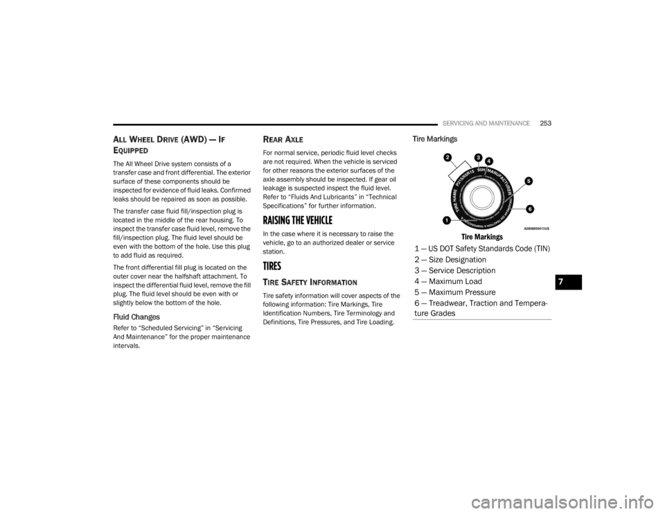
Tire Markings
Tire Markings
1 — US DOT Safety Standards Code (TIN)
2 — Size Designation
3 — Service Description
4 — Maximum Load
5 — Maximum Pressure
6 — Treadwear, Traction and Tempera -
ture Grades
7
20_LX_OM_EN_USC_t.book Page 253
Page 277 of 328

275
TECHNICAL SPECIFICATIONS
IDENTIFICATION DATA
VEHICLE IDENTIFICATION NUMBER
The Vehicle Identification Number (VIN) is on
the left front corner of the instrument panel. The
VIN is visible from outside of the vehicle through
the windshield.
Windshield VIN Location
NOTE:
It is illegal to remove or alter the VIN.
BRAKE SYSTEM
Your vehicle is equipped with dual hydraulic
brake systems. If either of the two hydraulic
systems loses normal capability, the remaining
system will still function. There will be some loss
of overall braking effectiveness. This may be
evident by increased pedal travel during
application, greater pedal force required to slow
or stop, and potential activation of the Brake
Warning Light.
In the event power assist is lost for any reason
(for example, repeated brake applications with
the engine OFF), the brakes will still function.
The effort required to brake the vehicle will be
much greater than that required with the power
system operating.
WHEEL AND TIRE TORQUE SPECIFICATIONS
Proper lug nut/bolt torque is very important to
ensure that the wheel is properly mounted to
the vehicle. Any time a wheel has been removed
and reinstalled on the vehicle, the lug nuts/
bolts should be torqued using a properly
calibrated torque wrench using a high quality six
sided (hex) deep wall socket.
TORQUE SPECIFICATIONS
**Use only authorized dealer recommended
lug nuts/bolts and clean or remove any dirt or
oil before tightening.
Lug Nut/Bolt
Torque **Lug Nut/
Bolt SizeLug Nut/Bolt
Socket Size
130 Ft-Lbs
(176 N·m) M14 x 1.50 22 mm
8
20_LX_OM_EN_USC_t.book Page 275