maintenance CHRYSLER 300 C 2008 1.G Owners Manual
[x] Cancel search | Manufacturer: CHRYSLER, Model Year: 2008, Model line: 300 C, Model: CHRYSLER 300 C 2008 1.GPages: 520, PDF Size: 5.43 MB
Page 2 of 520
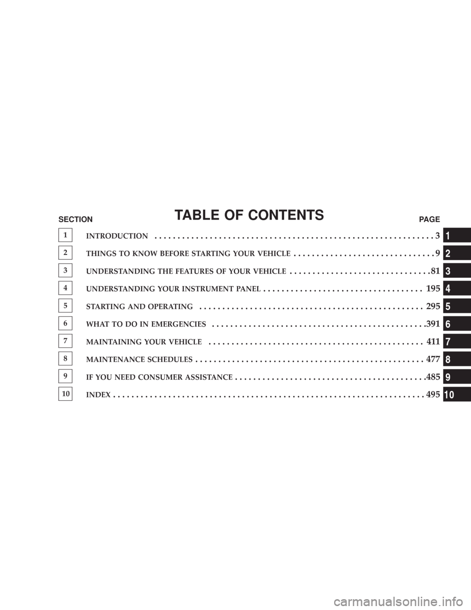
TABLE OF CONTENTSSECTIONPAGE
1INTRODUCTION.............................................................3
2THINGS TO KNOW BEFORE STARTING YOUR VEHICLE...............................9
3UNDERSTANDING THE FEATURES OF YOUR VEHICLE...............................81
4UNDERSTANDING YOUR INSTRUMENT PANEL................................... 195
5STARTING AND OPERATING................................................. 295
6WHAT TO DO IN EMERGENCIES...............................................391
7MAINTAINING YOUR VEHICLE............................................... 411
8MAINTENANCE SCHEDULES.................................................. 477
9IF YOU NEED CONSUMER ASSISTANCE..........................................485
10INDEX....................................................................495
1
2
3
4
5
6
7
8
9
10
Page 5 of 520
INTRODUCTION
This manual has been prepared with the assistance of
service and engineering specialists to acquaint you with
the operation and maintenance of your new vehicle. It is
supplemented by a Warranty Information Booklet and
various customer oriented documents. You are urged to
read these publications carefully. Following the instruc-
tions and recommendations in this manual will help
assure safe and enjoyable operation of your vehicle.
NOTE: After you read the manual, it should be stored
in the vehicle for convenient reference and remain with
the vehicle when sold, so that the new owner will be
aware of all safety warnings.
When it comes to service, remember that your dealer
knows your vehicle best, has the factory-trained techni-
cians and genuine Mopar\2parts, and is interested in
your satisfaction.
HOW TO USE THIS MANUAL
Consult the table of contents to determine which section
contains the information you desire.
The detailed index, at the rear of this manual, contains a
complete listing of all subjects.
Consult the following table for a description of the
symbols that may be used on your vehicle or throughout
this owner manual:
4 INTRODUCTION
Page 85 of 520

\3To Accelerate For Passing...............151
\1Adaptive Cruise Control (ACC) —
If Equipped...........................152
\3Adaptive Cruise Control (ACC) Operation . . . 154
\3Activating Adaptive Cruise Control (ACC) . . . 154
\3To Activate..........................155
\3To Set a Desired Speed.................156
\3To Cancel...........................157
\3ToTurnOff .........................157
\3To Resume Speed.....................158
\3To Vary The Speed Setting...............158
\3Setting The Following Distance In ACC......159
\3Adaptive Cruise Control (ACC) Menu......162\3Display Warnings & Maintenance..........165
\3Precautions While Driving With ACC.......168
\3General Information...................172
\1Rear Park Assist System — If Equipped.......172
\1Overhead Console......................176
\3Courtesy/Reading Lights................176
\3Sunglasses Storage....................177
\1Garage Door Opener — If Equipped.........177
\3Programming HomeLink\2...............178
\3Gate Operator/Canadian Programming.....181
\3Using HomeLink\2.....................182
\3Reprogramming a Single HomeLink\2Button . . 182
\3Security............................182
84 UNDERSTANDING THE FEATURES OF YOUR VEHICLE
Page 86 of 520

\3Troubleshooting Tips...................183
\3General Information...................183
\1Power Sunroof — If Equipped.............184
\3Opening Sunroof - Express..............185
\3Closing Sunroof - Express...............185
\3Pinch Protect Feature...................185
\3Pinch Protect Override.................185
\3Venting Sunroof - Express...............185
\3Sunshade Operation...................186
\3Wind Buffeting.......................186
\3Sunroof Maintenance...................186\3Ignition Off Operation..................186
\3Sunroof Fully Closed...................187
\1Electrical Power Outlets..................187
\3Electrical Outlet Use With Engine Off.......188
\1Cup Holders..........................189
\3Front Seat Cup Holders.................189
\3Rear Seat Cup Holders.................189
\1Storage..............................190
\3Console Features......................190
\3CargoArea..........................192
\1Load Leveling System — If Equipped........193
UNDERSTANDING THE FEATURES OF YOUR VEHICLE 85
3
Page 166 of 520

Display Warnings & Maintenance
ACC Blinded Warning
The ACC Blinded Warning will display when conditions
temporarily limit system performance. This most often
occurs at times of poor visibility, such as in snow, fog,
heavy rain, or when driving into direct sunlight (sunrise
or sunset). The ACC system may also become tempo-
rarily blinded due to obstructions, such as dirt or ice. In
these cases, the EVIC will display “ACC Blinded.”
UNDERSTANDING THE FEATURES OF YOUR VEHICLE 165
3
Page 167 of 520

If weather conditions are not a factor, the driver should
examine the sensor. It may require cleaning or removal of
an obstruction. The sensor is located behind the grille,
slightly offset from the center of the grille.
To keep the ACC System operating properly, it is impor-
tant to note the following maintenance items:•Always keep the sensor clean. Carefully wipe the
sensor lens with a soft cloth. Be cautious not to
damage the sensor lens.
•Do not remove any screws from the sensor or the
sensor mount. Doing so could cause an ACC system
malfunction or failure and require a sensor re-
alignment.
•If the sensor is damaged due to an accident, see your
authorized dealer for service.
•Do not attach or install any accessories near the sensor,
including transparent material or aftermarket grilles.
Doing so could cause an ACC system failure or
malfunction.
When the condition that deactivated the system is no
longer present, the system will return to the “ACC Off”
state and will resume function by simply reactivating it.
ACC Sensor Location
166 UNDERSTANDING THE FEATURES OF YOUR VEHICLE
Page 187 of 520
Sunshade Operation
The sunshade can be opened manually. However, the
sunshade will open automatically as the sunroof opens.
NOTE:The sunshade cannot be closed if the sunroof is
open.
Wind Buffeting
Wind buffeting can be described as the perception of
pressure on the ears or a helicopter type sound in the
ears. Your vehicle may exhibit wind buffeting with the
windows down, or the sunroof (if equipped) in certain
open or partially open positions. This is a normal occur-
rence and can be minimized. If the buffeting occurs with
the rear windows open, then open the front and rear
windows together to minimize the buffeting. If the
buffeting occurs with the sunroof open, then adjust the
sunroof opening to minimize the buffeting or open any
window.
Sunroof Maintenance
Use only a non-abrasive cleaner and a soft cloth to clean
the glass panel.
Ignition Off Operation
For vehicles not equipped with the Electronic Vehicle
Information Center (EVIC), the power sunroof switch
will remain active for 10 minutes after the ignition switch
is turned off. Opening either front door will cancel this
feature.
For vehicles equipped with the EVIC, the power sunroof
switch will remain active for up to 60 minutes after the
ignition switch is turned off. Opening either front door
will cancel this feature. The time is programmable. For
details, refer to “Delay Power Off to Accessories Until
Exit,” under “Personal Settings (Customer Program-
mable Features),” under “Electronic Vehicle Information
Center (EVIC)” in Section 4 of this manual.
186 UNDERSTANDING THE FEATURES OF YOUR VEHICLE
Page 199 of 520
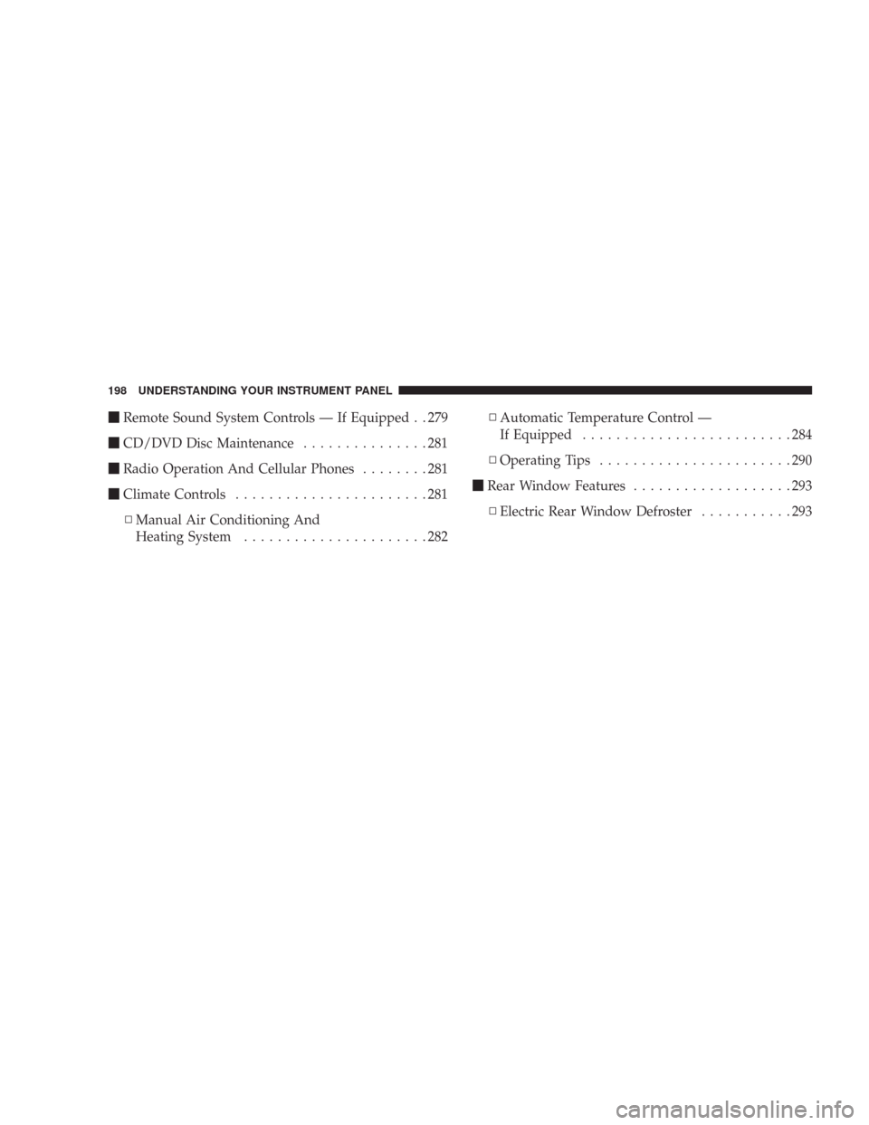
\1Remote Sound System Controls — If Equipped . . 279
\1CD/DVD Disc Maintenance...............281
\1Radio Operation And Cellular Phones........281
\1Climate Controls.......................281
\3Manual Air Conditioning And
Heating System......................282\3Automatic Temperature Control —
If Equipped.........................284
\3Operating Tips.......................290
\1Rear Window Features...................293
\3Electric Rear Window Defroster...........293
198 UNDERSTANDING YOUR INSTRUMENT PANEL
Page 205 of 520

the oil change indicator system (after performing the
scheduled maintenance) perform the following proce-
dure:
1. Turn the ignition switch to the ON position (Do not
start the engine).
2. Fully depress the accelerator pedal slowly three
times within 10 seconds.
3. Turn the ignition switch to the LOCK position.
NOTE:If the indicator message illuminates when you
start the vehicle, the oil change indicator system did not
reset. If necessary, repeat this procedure.
7. Tachometer
The red segments indicate the maximum permissible
engine revolutions-per-minute (r.p.m. x 1000) for each
gear range. Ease up on the accelerator before reaching the
red area.8. Engine Temperature Warning Light
This light will turn on and a single chime will
sound to warn of an overheated engine condition.
When this light turns on, the engine temperature
is critically hot. The vehicle should be turned off imme-
diately and serviced as soon as possible. (See page 393 for
more information.)
9. Anti-Lock Brake Light — If Equipped
This light monitors the Anti-Lock Brake System.
The light will turn on when the ignition switch is
turned to the ON position and may stay on for as long as
four seconds.
If the ABS light remains on or turns on while driving,
then the Anti-Lock portion of the brake system is not
functioning and service is required. However, the con-
ventional brake system will continue to operate normally
if the BRAKE warning light is not on.
204 UNDERSTANDING YOUR INSTRUMENT PANEL
Page 211 of 520
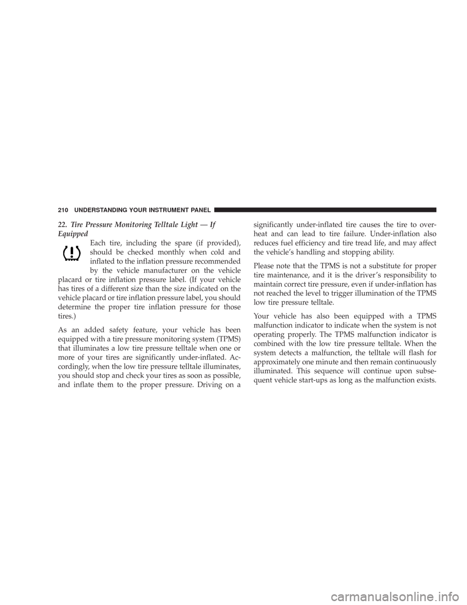
22. Tire Pressure Monitoring Telltale Light — If
Equipped
Each tire, including the spare (if provided),
should be checked monthly when cold and
inflated to the inflation pressure recommended
by the vehicle manufacturer on the vehicle
placard or tire inflation pressure label. (If your vehicle
has tires of a different size than the size indicated on the
vehicle placard or tire inflation pressure label, you should
determine the proper tire inflation pressure for those
tires.)
As an added safety feature, your vehicle has been
equipped with a tire pressure monitoring system (TPMS)
that illuminates a low tire pressure telltale when one or
more of your tires are significantly under-inflated. Ac-
cordingly, when the low tire pressure telltale illuminates,
you should stop and check your tires as soon as possible,
and inflate them to the proper pressure. Driving on asignificantly under-inflated tire causes the tire to over-
heat and can lead to tire failure. Under-inflation also
reduces fuel efficiency and tire tread life, and may affect
the vehicle’s handling and stopping ability.
Please note that the TPMS is not a substitute for proper
tire maintenance, and it is the driver ’s responsibility to
maintain correct tire pressure, even if under-inflation has
not reached the level to trigger illumination of the TPMS
low tire pressure telltale.
Your vehicle has also been equipped with a TPMS
malfunction indicator to indicate when the system is not
operating properly. The TPMS malfunction indicator is
combined with the low tire pressure telltale. When the
system detects a malfunction, the telltale will flash for
approximately one minute and then remain continuously
illuminated. This sequence will continue upon subse-
quent vehicle start-ups as long as the malfunction exists.
210 UNDERSTANDING YOUR INSTRUMENT PANEL