clock CHRYSLER 300 C 2009 1.G Owner's Manual
[x] Cancel search | Manufacturer: CHRYSLER, Model Year: 2009, Model line: 300 C, Model: CHRYSLER 300 C 2009 1.GPages: 537, PDF Size: 8.46 MB
Page 292 of 537
RW/FF
Pressing the RW (Rewind) or FF (Fast Forward) buttons
causes the tuner to search for the next channel in the
direction of the arrows.
TUNE Control (Rotary)
Turn the rotary Tune/Scroll control knob clockwise to
increase or counterclockwise to decrease the channel.
MUSIC TYPE Button — Except REU Radio
Pressing this button once will turn on the Music Type
mode for five seconds. Pressing the MUSIC TYPE button
or turning the Tune/Scroll control knob within five
seconds will allow the program format type to be se-
lected.
Toggle the MUSIC TYPE button again to select the music
type.By pressing the SEEK button when the Music Type
function is active, the radio will be tuned to the next
channel with the same selected Music Type name.
If a preset button is activated while in the Music Type
(Program Type) mode, the Music Type mode will be
exited and the radio will tune to the preset channel.
MUSIC TYPE Button — REU Radio
Pressing this button provides a MUSIC TYPES list from
which you can make a selection. Once a selection is
made, you can seek up, or down, or scan the channels
and the radio will tune to the next station matching the
selected format. There is no time-out for this screen.
Pressing the MUSIC TYPE button again will close the
MUSIC TYPE screen. Once closed, seek up, seek down,
and scan will no longer be based on your selection.
290 UNDERSTANDING YOUR INSTRUMENT PANEL
Page 297 of 537
•Two wireless infrared headsets allow rear seat passen-
gers to listen to the same or individual audio sources.
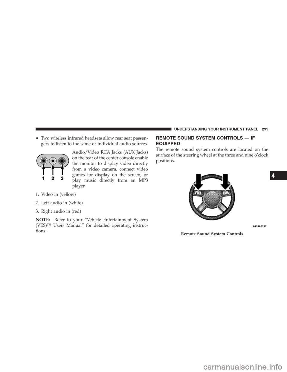
Audio/Video RCA Jacks (AUX Jacks)
on the rear of the center console enable
the monitor to display video directly
from a video camera, connect video
games for display on the screen, or
play music directly from an MP3
player.
1. Video in (yellow)
2. Left audio in (white)
3. Right audio in (red)
NOTE:Refer to your “Vehicle Entertainment System
(VES)™ Users Manual” for detailed operating instruc-
tions.REMOTE SOUND SYSTEM CONTROLS — IF
EQUIPPED
The remote sound system controls are located on the
surface of the steering wheel at the three and nine o’clock
positions.
Remote Sound System Controls
UNDERSTANDING YOUR INSTRUMENT PANEL 295
4
Page 298 of 537
The remote sound system controls are located on the
surface of the steering wheel at the three and nine o’clock
positions.
Vehicles equipped with steering wheel-mounted buttons
are also equipped with the Electronic Vehicle Information
Center (EVIC). The EVIC features a driver-interactive
display which is located in the instrument cluster.
The VOLUME button controls the sound level
of the sound system. Press the top of the
VOLUME button to increase the sound level.
Press the bottom of the VOLUME button to
decrease the sound level.Press the AUDIO MODE button to select the
Compass/Temp/Audio screen. This screen
displays radio and media mode information
depending on which radio is in the vehicle.
If the Compass/Temp/Audio screen is already displayed
when the AUDIO MODE button is pressed, then the
mode will change (i.e. from AM to FM, to Media mode,
etc., depending on which radio is in the vehicle).
When the EVIC is in the Compass/Temp/
Audio screen, press the FUNCTION SELECT
button to operate various radio, media, and
Universal Customer Interface (UCI) functions
(i.e., advance presets, select next folder, jump to
or start playing songs in playlists, etc., depend-
ing on which radio is in the vehicle and if
equipped with UCI).
VOL-
UME
Button
AUDIO
MODE
Button
FUNC-
TION
SELECT
Button
296 UNDERSTANDING YOUR INSTRUMENT PANEL
Page 316 of 537
CAUTION!
Damage to the transmission may occur if the follow-
ing precautions are not observed:
•Shift into PARK only after the vehicle has come to
a complete stop.
•Shift into or out of REVERSE only after the
vehicle has come to a complete stop and the engine
is at idle speed.
•Do not shift from REVERSE, PARK, or NEUTRAL
into any forward gear when the engine is above
idle speed.
•Before shifting into any gear, make sure your foot
is firmly on the brake pedal.
Keyless Go (If Equipped)
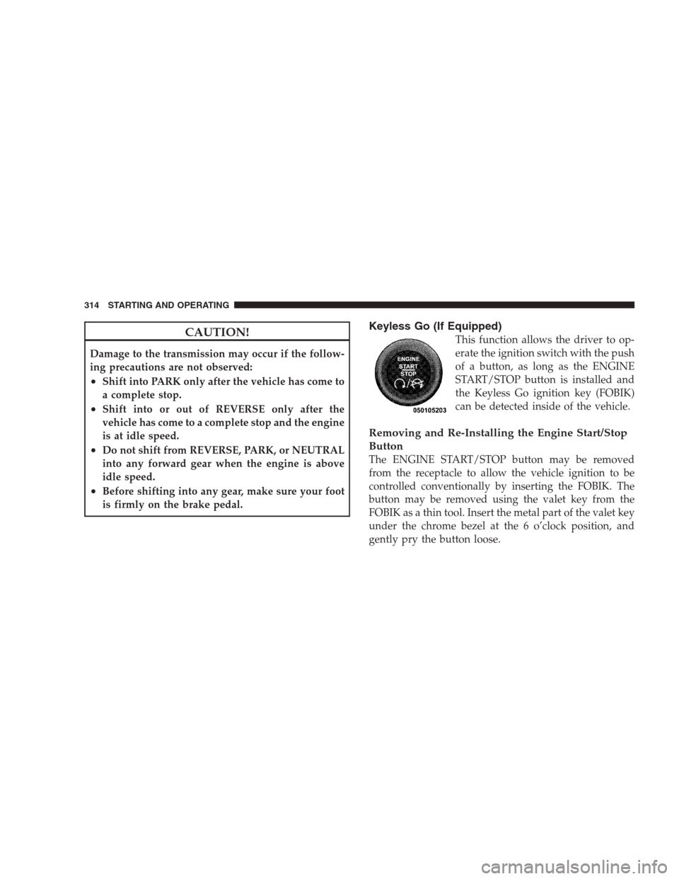
This function allows the driver to op-
erate the ignition switch with the push
of a button, as long as the ENGINE
START/STOP button is installed and
the Keyless Go ignition key (FOBIK)
can be detected inside of the vehicle.
Removing and Re-Installing the Engine Start/Stop
Button
The ENGINE START/STOP button may be removed
from the receptacle to allow the vehicle ignition to be
controlled conventionally by inserting the FOBIK. The
button may be removed using the valet key from the
FOBIK as a thin tool. Insert the metal part of the valet key
under the chrome bezel at the 6 o’clock position, and
gently pry the button loose.
314 STARTING AND OPERATING
Page 413 of 537
WARNING!
To avoid possible personal injury, handle the wheel
covers with care to avoid contact with the metal edges
and retention teeth.
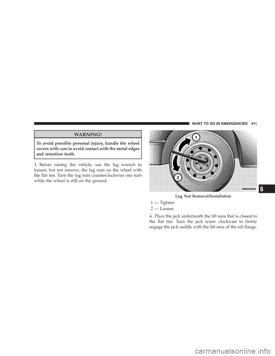
3. Before raising the vehicle, use the lug wrench to
loosen, but not remove, the lug nuts on the wheel with
the flat tire. Turn the lug nuts counterclockwise one turn
while the wheel is still on the ground.
4. Place the jack underneath the lift area that is closest to
the flat tire. Turn the jack screw clockwise to firmly
engage the jack saddle with the lift area of the sill flange.
Lug Nut Removal/Installation
1 — Tighten
2 — Loosen
WHAT TO DO IN EMERGENCIES 411
6
Page 415 of 537
5. Raise the vehicle just enough to remove the flat tire
and install the spare tire.
WARNING!
Raising the vehicle higher than necessary can make
the vehicle less stable. It could slip off the jack and
hurt someone near it. Raise the vehicle only enough
to remove the tire.
6. Remove the lug nuts, wheel cover (if equipped), and
tire. Remove the cover by hand. Do not pry it off.
7. Mount the spare tire.
NOTE:For vehicles so equipped, do not attempt to
install a center cap or wheel cover on the compact spare.
However, when reinstalling the road tire, follow the
procedure under “Wheel Cover or Center Cap Installa-
tion” in place of the remaining steps in this procedure.8. Install the lug nuts with the cone shaped end of the
nut toward the wheel. Lightly tighten the lug nuts. To
avoid the risk of forcing the vehicle off the jack, do not
tighten the lug nuts fully until the vehicle is lowered to
the ground.
9. Lower the vehicle to the ground by turning the jack
handle counterclockwise.
10. Finish tightening the lug nuts. Push down on the
wrench while tightening for increased leverage. Alternate
lug nuts until each nut has been tightened twice. The
correct tightness of each lug nut is 100 ft/lb. (135 N·m). If
in doubt about the correct tightness, have them checked
with a torque wrench by your authorized dealer or at a
service station.
11. Stow the jack, tools and flat tire. Make sure the base
of the jack faces the rear of the vehicle before tightening
down the fastener.
WHAT TO DO IN EMERGENCIES 413
6
Page 418 of 537
3. Align the valve notch in the wheel cover with the
valve stem on the wheel. Install the cover by hand,
snapping the cover over the two lug nuts. Do not use a
hammer or excessive force to install the cover.
4. Install the remaining lug nuts with the cone shaped
end of the nut toward the wheel. Lightly tighten the lug
nuts. To avoid the risk of forcing the vehicle off the jack,
do not tighten the lug nuts fully until the vehicle is
lowered to the ground.
5. Lower the vehicle to the ground by turning the jack
handle counterclockwise.
6. Finish tightening the lug nuts. Push down on the
wrench while tightening for increased leverage. Alternate
lug nuts until each nut has been tightened twice. The
correct tightness of each lug nut is 100 ft/lb. (135 N·m). If
in doubt about the correct tightness, have them checked
with a torque wrench by your authorized dealer or at a
service station.7. For vehicles equipped with center caps, install the
center cap by hand. Do not use a hammer or excessive
force to install the center cap.
8. Stow the jack, tools, and spare tire. Make sure the base
of the jack faces the rear of the vehicle before tightening
down the fastener.
WARNING!
A loose tire or jack thrown forward in a collision or
hard stop could endanger the occupants of the ve-
hicle. Always stow the jack parts and the spare tire in
the places provided.
416 WHAT TO DO IN EMERGENCIES
Page 467 of 537
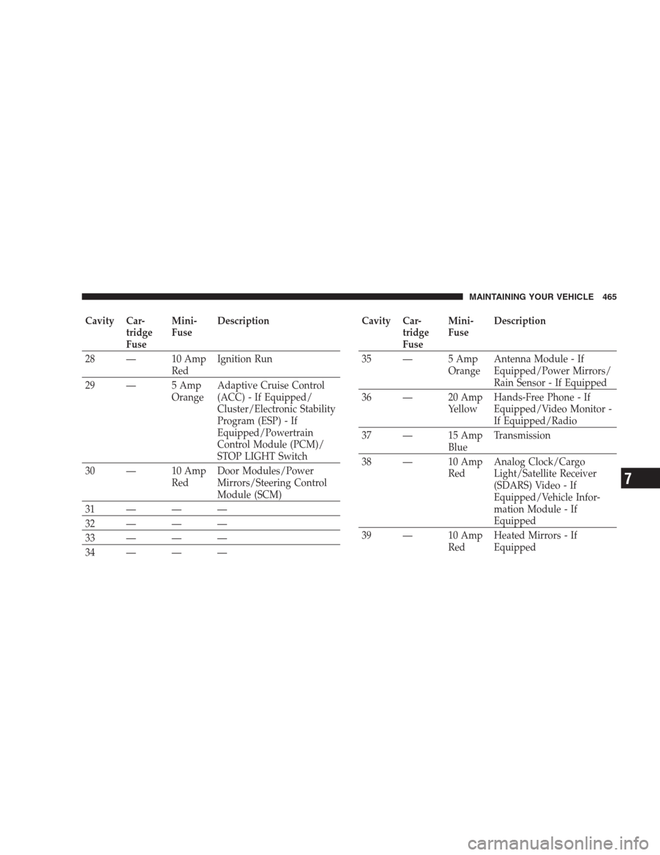
Cavity Car-
tridge
FuseMini-
FuseDescription
28 — 10 Amp
RedIgnition Run
29 — 5 Amp
OrangeAdaptive Cruise Control
(ACC) - If Equipped/
Cluster/Electronic Stability
Program (ESP) - If
Equipped/Powertrain
Control Module (PCM)/
STOP LIGHT Switch
30 — 10 Amp
RedDoor Modules/Power
Mirrors/Steering Control
Module (SCM)
31 — — —
32 — — —
33 — — —
34 — — —Cavity Car-
tridge
FuseMini-
FuseDescription
35 — 5 Amp
OrangeAntenna Module - If
Equipped/Power Mirrors/
Rain Sensor - If Equipped
36 — 20 Amp
YellowHands-Free Phone - If
Equipped/Video Monitor -
If Equipped/Radio
37 — 15 Amp
BlueTransmission
38 — 10 Amp
RedAnalog Clock/Cargo
Light/Satellite Receiver
(SDARS) Video - If
Equipped/Vehicle Infor-
mation Module - If
Equipped
39 — 10 Amp
RedHeated Mirrors - If
Equipped
MAINTAINING YOUR VEHICLE 465
7
Page 471 of 537
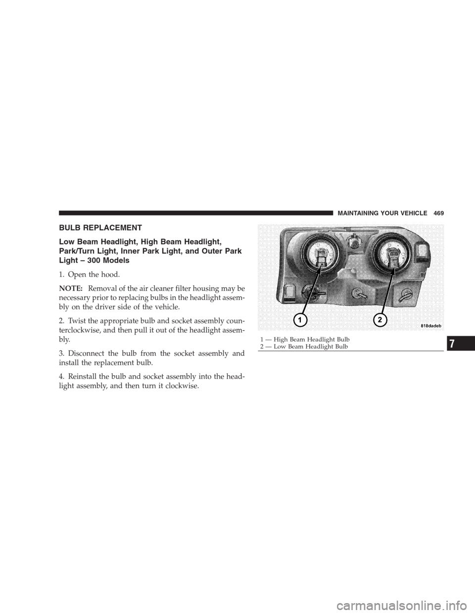
BULB REPLACEMENT
Low Beam Headlight, High Beam Headlight,
Park/Turn Light, Inner Park Light, and Outer Park
Light – 300 Models
1. Open the hood.
NOTE:Removal of the air cleaner filter housing may be
necessary prior to replacing bulbs in the headlight assem-
bly on the driver side of the vehicle.
2. Twist the appropriate bulb and socket assembly coun-
terclockwise, and then pull it out of the headlight assem-
bly.
3. Disconnect the bulb from the socket assembly and
install the replacement bulb.
4. Reinstall the bulb and socket assembly into the head-
light assembly, and then turn it clockwise.
1 — High Beam Headlight Bulb
2 — Low Beam Headlight BulbMAINTAINING YOUR VEHICLE 4697
Page 475 of 537
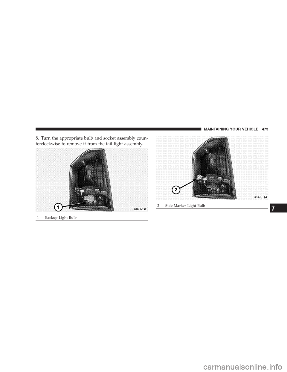
8. Turn the appropriate bulb and socket assembly coun-
terclockwise to remove it from the tail light assembly.
1 — Backup Light Bulb
2 — Side Marker Light BulbMAINTAINING YOUR VEHICLE 4737