ECU CHRYSLER 300 SRT 2014 2.G User Guide
[x] Cancel search | Manufacturer: CHRYSLER, Model Year: 2014, Model line: 300 SRT, Model: CHRYSLER 300 SRT 2014 2.GPages: 132, PDF Size: 4.64 MB
Page 3 of 132
INTRODUCTION/WELCOME
WELCOME FROM CHRYSLER
GROUPLLC ..................2
CONTROLS AT A GLANCE
DRIVER COCKPIT...............4
INSTRUMENT CLUSTER ...........6
GETTING STARTED
KEYFOB ....................8
REMOTE START...............10
KEYLESS ENTER-N-GO™ ..........10
SECURITY ALARM ..............13
SEATBELT ...................14
SUPPLEMENTAL RESTRAINT
SYSTEM (SRS) — AIR BAGS .........14
CHILD RESTRAINTS .............15
FRONTSEATS ................18
REAR SEAT ...................21
HEATEDSEATS ................21
HEATED AND COOLED CUPHOLDERS..22
ADJUSTABLE PEDALS ............23
TILT/TELESCOPING STEERING
COLUMN ...................24
OPERATING YOUR VEHICLE
ENGINE BREAK-IN
RECOMMENDATIONS ............25
TURN SIGNAL/WIPER/WASHER/HIGH
BEAM LEVER . ................26
HEADLIGHT SWITCH ............27
SPEED CONTROL ..............28
ELECTRONIC SHIFTER – 3.6L ENGINE . . 32
TRANSMISSION MODES/AUTOSTICK® . . 33
CLIMATE CONTROLS ............35
BLIND SPOT MONITORING ........36
POWER SUNROOF ..............37
WIND BUFFETING ..............39
ELECTRONICS
YOUR VEHICLE'S SOUND SYSTEM ....40
IDENTIFYING YOUR RADIO ........42
Uconnect® 8.4 & 8.4N AT A GLANCE ....42
RADIO .....................44
SiriusXM SATELLITE RADIO .........45
STEERING WHEEL AUDIO CONTROLS . . 47
SETTING THE ANALOG CLOCK .....47
iPod®/CD/AUX CONTROLS .........48
GARMIN® NAVIGATION (8.4N Only) ....48
SiriusXM TRAVEL LINK (8.4N ONLY) . . . . 51
PLAYING iPod/USB/MP3 DEVICES .....52
Uconnect® PHONE (Bluetooth® HANDS FREE
CALLING)...................54
Uconnect® VOICE COMMAND
(8.4&8.4NONLY) ...............57
ELECTRONIC VEHICLE INFORMATION
CENTER (EVIC) ...............60
PROGRAMMABLE FEATURES .......61UNIVERSAL GARAGE DOOR OPENER
(HomeLink®)
..................62
POWER OUTLETS ..............64
UTILITY
TRAILER TOWING WEIGHTS (MAXIMUM
TRAILER WEIGHT RATINGS) . ......66
RECREATIONAL TOWING (BEHIND
MOTORHOME, ETC.) . . ..........66
SRTAUTOSTICK® .................67
ELECTRONIC CONTROL DAMPING
SYSTEM....................68
PERFORMANCE FEATURES ........69
SUMMER/THREE-SEASON TIRES ......71
WHAT TO DO IN EMERGENCIESROADSIDE ASSISTANCE..........72
INSTRUMENT CLUSTER WARNING
LIGHTS .....................72
IF YOUR ENGINE OVERHEATS .......76
JACKING AND TIRE CHANGING .....76
TIREFIT KIT ..................82
BATTERY LOCATION ............87
JUMP-STARTING ...............88
SHIFT LEVER OVERRIDE — 5 SPEED
TRANSMISSION ...............90
TOWING A DISABLED VEHICLE . . ....92
FREEING A STUCK VEHICLE ........93
EVENT DATA RECORDER (EDR) . . . . . . 93
MAINTAINING YOUR VEHICLEOPENING THE HOOD . . . ........95
FUEL DOOR RELEASE ...........95
ENGINE COMPARTMENT .........97
FLUIDSANDCAPACITIES .........100
MAINTENANCE SCHEDULE . . . . . . . 103
FUSES .....................112
TIRE PRESSURES ...............117
WHEEL AND WHEEL TRIM CARE . . . . . 117
EXTERIOR BULBS ..............118
CONSUMER ASSISTANCE
CHRYSLER GROUP LLC CUSTOMER
CENTER....................119
CHRYSLER CANADA INC. CUSTOMER
CENTER ....................119
PUBLICATIONS ORDERING ........119
ASSISTANCE FOR THE HEARING
IMPAIRED ...................119
REPORTING SAFETY DEFECTS IN THE
UNITEDSTATES ...............120
MOPAR® ACCESSORIESAUTHENTIC ACCESSORIES BY
MOPAR® ...................121
INDEX................... 122
FREQUENTLY ASKED QUESTIONS
FREQUENTLY ASKED QUESTIONS . . . . 125
TABLE OF CONTENTS
Page 9 of 132
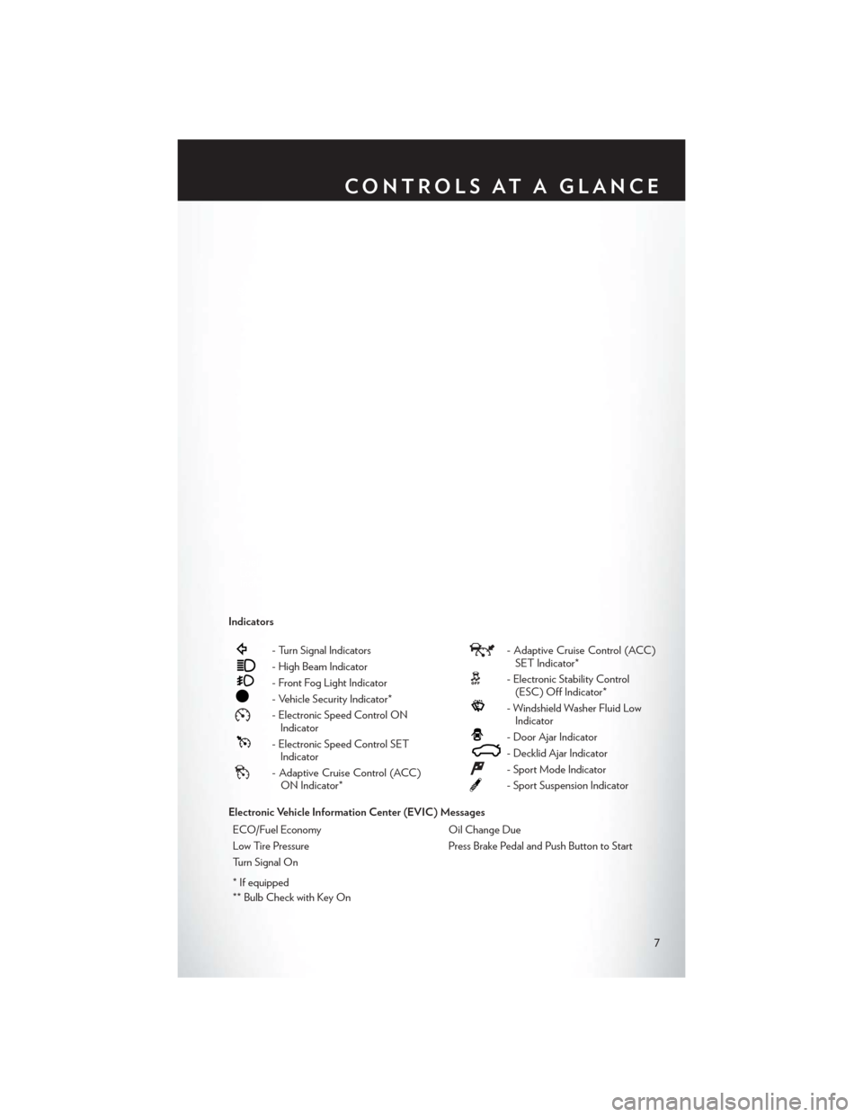
Indicators
- Turn Signal Indicators
- High Beam Indicator
- Front Fog Light Indicator
- Vehicle Security Indicator*
- Electronic Speed Control ONIndicator
- Electronic Speed Control SETIndicator
- Adaptive Cruise Control (ACC)ON Indicator*
- Adaptive Cruise Control (ACC)SET Indicator*
- Electronic Stability Control(ESC) Off Indicator*
- Windshield Washer Fluid LowIndicator
- Door Ajar Indicator
- Decklid Ajar Indicator
- Sport Mode Indicator
- Sport Suspension Indicator
Electronic Vehicle Information Center (EVIC) Messages ECO/Fuel Economy Oil Change Due
Low Tire Pressure Press Brake Pedal and Push Button to Start
Turn Signal On
* If equipped
** Bulb Check with Key On
CONTROLS AT A GLANCE
7
Page 12 of 132
REMOTE START
• Press the REMOTE START buttonx2on the Key Fob twice within five seconds. Pressing
the REMOTE START button a third time shuts the engine off.
• To drive the vehicle, press the UNLOCK button and cycle the ignition to the ON/RUN position.
• With remote start, the engine will only run for 15 minutes (timeout) unless the ignition is cycled to the ON/RUN position.
• The vehicle must be cycled to the ON/RUN position after two consecutive timeouts.
WARNING!
• Do not start or run an engine in a closed garage or confined area. Exhaust gas contains Carbon Monoxide (CO) which is odorless and colorless. Carbon Monoxide is poisonous
and can cause you or others to be severely injured or killed when inhaled.
• Keep Key Fob transmitters away from children. Operation of the Remote Start System,
windows, door locks or other controls could cause you and others to be severely injured or
killed.
KEYLESS ENTER-N-GO™
• The Keyless Enter-N-Go™ system is an enhancement to the vehicle's Key Fob. This featureallows you to lock and unlock the vehicle's door(s) and trunk without having to press the Key
Fob lock or unlock buttons, as well as starting and stopping the vehicle with the press of a
button.
To Unlock From The Driver Or Passenger Side:
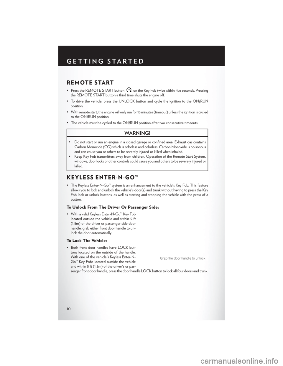
• With a valid Keyless Enter-N-Go™ Key Foblocated outside the vehicle and within 5 ft
(1.5m) of the driver or passenger side door
handle, grab either front door handle to un-
lock the door automatically.
To Lock The Vehicle:
• Both front door handles have LOCK but-tons located on the outside of the handle.
With one of the vehicle's Keyless Enter-N-
Go™ Key Fobs located outside the vehicle
and within 5 ft (1.5m) of the driver's or pas-
senger front door handle, press the door handle LOCK button to lock all four doors and trunk.
GETTING STARTED
10
Page 15 of 132

Accessory Positions With Engine Off
NOTE:
The following functions are with the driver’s foot OFF the Brake Pedal (transmission in PARK or
NEUTRAL).
Beginning With The Ignition Switch In The OFF Position:
• Press the ENGINE START/STOP button once to change the ignition switch to the ACCposition.
• Press the ENGINE START/STOP button a second time to change the ignition switch to the ON/RUN position.
• Press the ENGINE START/STOP button a third time to return the ignition switch to the OFF position.
NOTE:
If the ignition switch is left in the ACC or
ON/RUN (engine not running) position and
the transmission is in PARK, the system will
automatically time out after 30 minutes of in-
activity and the ignition will switch to the OFF
position.
SECURITY ALARM
To Arm:
• Press the Keyless Enter-N-Go™ START/STOP button until the Electronic Vehicle Information Center (EVIC) indicates that the vehicle ignition is “OFF”. Press the power door lock switch
while the door is open, press the Key Fob LOCK button, or with one of the Key Fobs located
outside the vehicle and within 5 ft (1.5 m) of the driver's and passenger front door handles,
press the Keyless Enter-N-Go™ LOCK button located on the door handle.
NOTE:
After pressing the Keyless Enter-N-Go™ LOCK button, you must wait two seconds before you
can lock or unlock the vehicle via the door handle.
To Disarm:
• Press the Key Fob UNLOCK button or with one of the Key Fobs located outside the vehicle and within 5 ft (1.5 m) of the driver's and passenger front door handles, grab the Keyless
Enter-N-Go™ door handle and enter the vehicle, then press the Keyless Enter-N-Go™
START/STOP button (requires at least one valid Key Fob in the vehicle).
GETTING STARTED
13
Page 17 of 132

• This vehicle may be equipped with Supplemental Side Air Bag Inflatable Curtains (SABIC) toprotect the driver, front, and rear passengers sitting next to a window. The SABIC air bags are
located above the side windows and their covers are labeled: SRS AIRBAG.
• If the Air Bag Warning Light
is not on during starting, stays on, or turns on while driving,
have the vehicle serviced by an authorized service center immediately.
• Refer to the Owner's Manual on the DVD for further details regarding the Supplemental Restraint System (SRS).
WARNING!
• Relying on the air bags alone could lead to more severe injuries in a collision. The air bags
work with your seat belt to restrain you properly. In some collisions, the air bags won't
deploy at all. Always wear your seat belts even though you have air bags.
• Being too close to the steering wheel or instrument panel during Advanced Front Air Bag
deployment could cause serious injury, including death. Air bags need room to inflate. Sit
back, comfortably extending your arms to reach the steering wheel or instrument panel.
• Supplemental Side Air Bag Inflatable Curtains and Supplemental Seat-Mounted Side Air
Bags need room to inflate. Do not lean against the door or window. Sit upright in the
center of the seat.
• Being too close to the Supplemental Side Air Bag Inflatable Curtain and/or Seat-
Mounted Side Air Bag during deployment could cause you to be severely injured or killed.
• Do not drive your vehicle after the air bags have deployed. If you are involved in another
collision, the air bags will not be in place to protect you.
• After any collision, the vehicle should be taken to an authorized dealer immediately.
CHILD RESTRAINTS
• Children 12 years or younger should ride properly buckled up in a rear seat, if available. According to crash statistics, children are safer when properly restrained in the rear seats rather
than in the front.
• Every state in the United States and all Canadian provinces require that small children ride in proper restraint systems. This is the law, and you can be prosecuted for ignoring it.
NOTE:
• For additional information, refer to www.seatcheck.org or call 1–866–SEATCHECK (1–866–732–8243).
• Canadian residents, should refer to Transport Canada’s website for additional information: http://www.tc.gc.ca/eng/roadsafety/safedrivers-childsafety-index-53.htm
GETTING STARTED
15
Page 19 of 132

4. Tighten all of the straps as you push the child restraint rearward and downward into the seat.Remove slack in the straps according to the child restraint manufacturer’s instructions.
5. Test that the child restraint is installed tightly by pulling back and forth on the child seat at the belt path. It should not move more than 1 inch (25.4 mm) in any direction.
Installing The Child Restraint Using The Vehicle Seat Belts
• The seat belts in the passenger seating positions are equipped with a Switchable AutomaticLocking Retractor (ALR) that is designed to keep the lap portion of the seat belt tight around
the child restraint. Any seat belt system will loosen with time, so check the belt occasionally,
and pull it tight if necessary.
• Always use the tether anchor when using the seat belt to install a forward facing child restraint, up to the recommended weight limit of the child restraint.
To Install A Child Seat Using An ALR:
1. Pull enough of the seat belt webbing from the retractor to pass it through the belt path of the
child restraint. Do not twist the belt webbing in the belt path.
2. Slide the latch plate into the buckle until you hear a “click.”
3. Pull on the webbing to make the lap portion tight against the child seat.
4. To lock the seat belt, pull down on the shoulder part of the belt until you have pulled all the seat belt webbing out of the retractor. Then, allow the webbing to retract back into the retractor.
As the webbing retracts, you will hear a clicking sound. This means the seat belt is now in the
Automatic Locking mode.
5. Try to pull the webbing out of the retractor. If it is locked, you should not be able to pull out any webbing. If the retractor is not locked, repeat the last step.
6. Finally, pull up on any extra webbing to tighten the lap portion around the child restraint while you push the child restraint rearward and downward into the vehicle seat.
7. If the child restraint has a top tether strap and the seating position has a top tether anchorage, connect the tether strap to the anchorage and tighten the tether strap. See below for
directions to attach a tether anchor.
8. Test that the child restraint is installed tightly by pulling back and forth on the child seat at the belt path. It should not move more than 1 inch (25.4 mm) in any direction.
Installing The Top Tether Strap (With Either Lower Anchors Or Vehicle
Seat Belt):
• When installing a forward-facing child restraint, always secure the top tether strap, up to thetether anchor weight limit, whether the child restraint is installed with the lower anchors or the
vehicle seat belt.
1. Rotate or lift the cover to access the anchor directly behind the seat where you are placing the child restraint.
2. Route the tether strap to provide the most direct path for the strap between the anchor and the child seat.
GETTING STARTED
17
Page 20 of 132

3. If your vehicle is equipped with adjustable rear head restraints, raise the head restraint, andwhere possible, route the tether strap under the head restraint and between the two posts.
If not possible, lower the head restraint and pass the tether strap around the outboard side of
the head restraint.
4. Attach the tether strap hook of the child restraint to the top tether anchorage and remove slack in the tether strap according to the child restraint manufacturer’s instructions.
WARNING!
• In a collision, an unrestrained child, even a tiny baby, can become a projectile inside the vehicle. The force required to hold even an infant on your lap could become so great that
you could not hold the child, no matter how strong you are. The child and others could be
severely injured or killed. Any child riding in your vehicle should be in a proper restraint for
the child's size.
• Rearward-facing child seats must never be used in the front seat of a vehicle with a front
passenger air bag. An air bag deployment could cause severe injury or death to infants in
this position.
• Only use a rearward-facing child restraint in a vehicle with a rear seat.
• Improper installation of a child restraint to the LATCH anchorages can lead to failure of an
infant or child restraint. The child could be severely injured or killed. Follow the manufac-
turer’s directions exactly when installing an infant or child restraint.
• An incorrectly anchored tether strap could lead to increased head motion and possible
injury to the child. Use only the anchor positions directly behind the child seat to secure a
child restraint top tether strap.
• If your vehicle is equipped with a split rear seat, make sure the tether strap does not slip into
the opening between the seatbacks as you remove slack in the strap.
FRONT SEATS
Power Seats
• The power seat switches are located on theoutboard side of the front seat cushions.
• The seat switch controls, forward/backward, up/down or to recline the seat. The passen-
ger’s seat will move up or down, forward or
rearward.
• The recline switch controls the angle of the seatback. Press the switch forward or rear-
ward and the seatback will move in either
direction.
GETTING STARTED
18
Page 23 of 132
REAR SEAT
Folding Rear Seatback
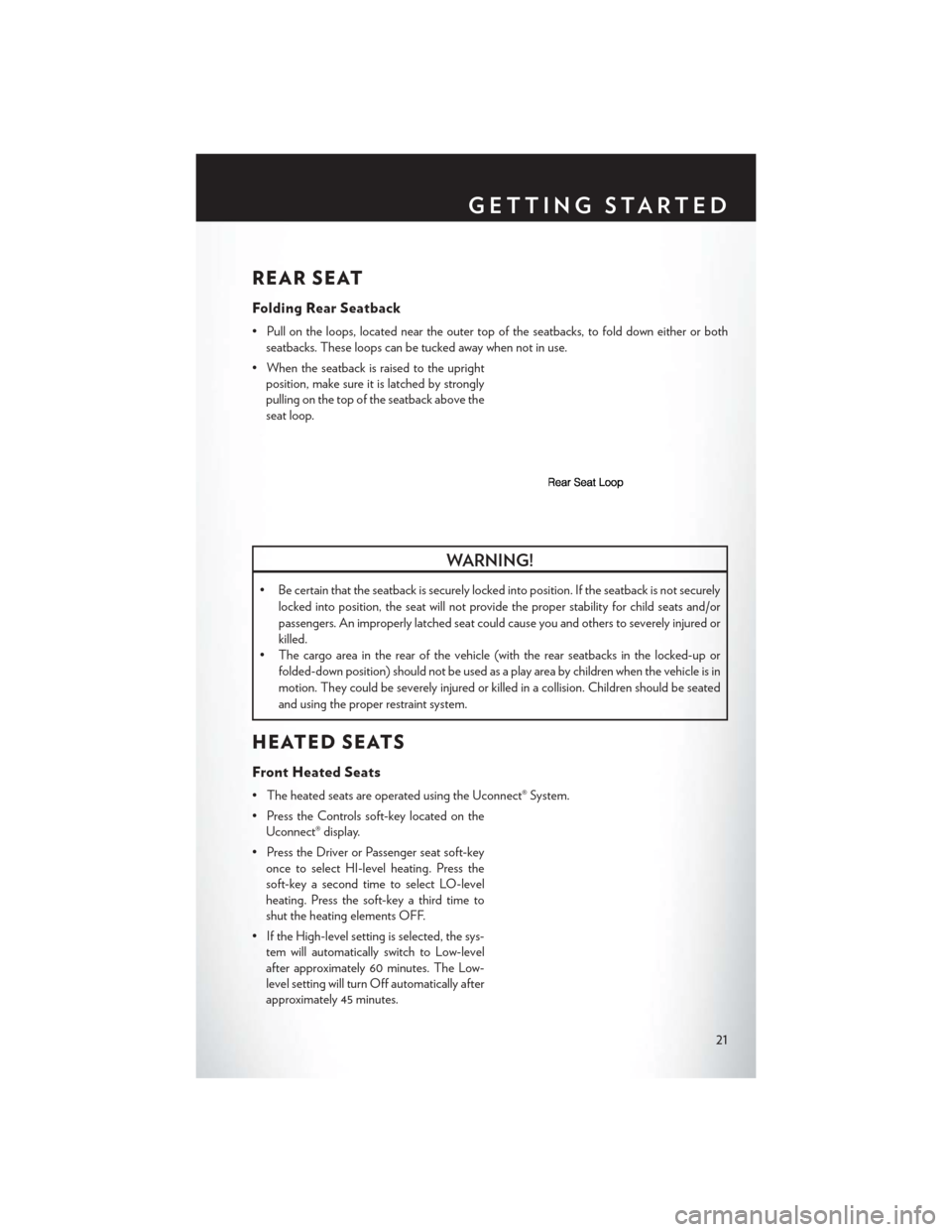
• Pull on the loops, located near the outer top of the seatbacks, to fold down either or bothseatbacks. These loops can be tucked away when not in use.
• When the seatback is raised to the upright position, make sure it is latched by strongly
pulling on the top of the seatback above the
seat loop.
WARNING!
• Be certain that the seatback is securely locked into position. If the seatback is not securely
locked into position, the seat will not provide the proper stability for child seats and/or
passengers. An improperly latched seat could cause you and others to severely injured or
killed.
• The cargo area in the rear of the vehicle (with the rear seatbacks in the locked-up or
folded-down position) should not be used as a play area by children when the vehicle is in
motion. They could be severely injured or killed in a collision. Children should be seated
and using the proper restraint system.
HEATED SEATS
Front Heated Seats
• The heated seats are operated using the Uconnect® System.
• Press the Controls soft-key located on theUconnect® display.
• Press the Driver or Passenger seat soft-key once to select HI-level heating. Press the
soft-key a second time to select LO-level
heating. Press the soft-key a third time to
shut the heating elements OFF.
• If the High-level setting is selected, the sys- tem will automatically switch to Low-level
after approximately 60 minutes. The Low-
level setting will turn Off automatically after
approximately 45 minutes.
GETTING STARTED
21
Page 41 of 132
NOTE:
Any release of the switch will stop the movement and the shade will remain in a partially closed
condition until the switch is pushed and held forward again.
Pinch Protection Feature
• This feature will detect an obstruction in the opening of the sunroof during Express Closeoperation. If an obstruction in the path of the sunroof is detected, the sunroof will automati-
cally retract. Remove the obstruction if this occurs. Next, press the switch forward and release
to Express Close.
NOTE:
If three consecutive sunroof close attempts result in Pinch Protect reversals, the fourth close
attempt will be a Manual Close movement with Pinch Protect disabled.
WARNING!
• Do not let children play with the sunroof. Never leave children unattended in a vehicle, or with access to an unlocked vehicle. Do not leave the Key Fob in or near the vehicle, and do
not leave the ignition of a vehicle equipped with Keyless Enter-N-Go™ in the ACC or
ON/RUN position. Occupants, particularly unattended children, can become entrapped
by the power sunroof while operating the power sunroof switch. Such entrapment may
result in serious injury or death.
• In a collision, there is a greater risk of being thrown from a vehicle with an open sunroof.
You could also be severely injured or killed. Always fasten your seat belt properly and make
sure all passengers are properly secured.
• Do not allow small children to operate the sunroof. Never allow your fingers, other body
parts, or any object to project through the sunroof opening. Injury may result.
WIND BUFFETING
• Wind buffeting can be described as a helicopter-type percussion sound. If buffeting occurswith the rear windows open, adjust the front and rear windows together.
• If buffeting occurs with the sunroof open, adjust the sunroof opening, or adjust any window. This will minimize buffeting.
OPERATING YOUR VEHICLE
39
Page 64 of 132
UNIVERSAL GARAGE DOOR OPENER
(HomeLink®)
• HomeLink® replaces up to three hand-held transmitters that operate devices such as garagedoor openers, motorized gates, lighting or home security systems. The HomeLink® unit is
powered by your vehicles 12 Volt battery.
• The HomeLink® buttons that are located in the overhead console or sunvisor designate the three different HomeLink® channels.
• The HomeLink® indicator is located above the center button.
Before You Begin Programming
HomeLink®
• Ensure that your vehicle is parked outside of the garage before you begin programming.
• For efficient programming and accurate transmission of the radio-frequency signal,
it is recommended that a new battery be
placed in the hand-held transmitter of the
device that is being programmed to the
HomeLink® system.
• Erase all channels before you begin pro- gramming. To erase the channels, place the
ignition switch into the ON/RUN position,
then press and hold the two outside
HomeLink® buttons (I and III) for up to 20 seconds or until the red indicator flashes.
NOTE:
Erasing all channels should only be performed when programming HomeLink® for the first time.
Do not erase channels when programming additional buttons.
• If you have any problems, or require assistance, please call toll-free 1-800-355-3515 or, on the Internet at www.HomeLink.com for information or assistance.
Programming A Rolling Code
NOTE:
For programming Garage Door Openers that were manufactured after 1995. These Garage
Door Openers can be identified by the “LEARN” or “TRAIN” button located where the hanging
antenna is attached to the Garage Door Opener. It is NOT the button that is normally used to
open and close the door. The name and color of the button may vary by manufacturer.
1. Place the ignition switch into the ON/RUN position.
2. Place the hand-held transmitter 1 to 3 in (3 to 8 cm) away from the HomeLink® button you wish
to program while keeping the HomeLink® indicator light in view.
3. Simultaneously press and hold both the HomeLink® button you want to program and the hand-held transmitter button.
ELECTRONICS
62