torque CHRYSLER ASPEN 2008 2.G Owners Manual
[x] Cancel search | Manufacturer: CHRYSLER, Model Year: 2008, Model line: ASPEN, Model: CHRYSLER ASPEN 2008 2.GPages: 479, PDF Size: 4.3 MB
Page 268 of 479

STARTING AND OPERATING
CONTENTS
mStarting Procedures.....................271
NAutomatic Transmission................271
NNormal Starting......................271
mEngine Block Heater ± If Equipped..........274
mAutomatic Transmission..................274
NBrake/Transmission Interlock System.......274
NGear Ranges.........................275
NOverdrive Operation...................277
NWhen To Use Tow/Haul Mode...........278NTorque Converter Clutch................279
mFour-Wheel Drive Operation...............280
NNV 140 Transfer Case Operating
Information/Precautions ± If Equipped......280
NNV 244 Generation II Transfer Case Operating
Information / Precautions...............280
NShifting Procedure - NV 244 Generation II
Transfer Case........................284
mDriving On Slippery Surfaces..............286
mDriving Through Water..................286
5
Page 278 of 479
ª1º 1st
For driving up very steep hills and for engine braking at
low speeds (25 mph {40 km/h} or less) when going
downhill. To prevent excessive engine speed do not
exceed 25 mph (40 km/h) in this range.
OVERDRIVE Operation
The OVERDRIVE automatic transmission contains an
electronically controlled fourth and fifth (if equipped)
speed (OVERDRIVE). The transmission will automati-
cally shift from DRIVE to OVERDRIVE if the following
conditions are present:
²the transmission selector is in DRIVE;
²the engine coolant has reached normal operating tem-
perature;
²vehicle speed is above approximately 30 mph (48
km/h);
²the TOW/HAUL switch has not been activated;
²transmission has reached normal operating tempera-
ture.
NOTE:If the vehicle is started in extremely cold tem-
peratures, the transmission may not shift into OVER-
DRIVE and will automatically select the most desirable
gear for operation at this temperature. Normal operation
will resume when the transmission fluid temperature has
risen to a suitable level. Refer also to the Note under
torque converter clutch, later in this section.
If the transmission temperature gets extremely hot, the
transmission will automatically select the most desirable
gear for operation at this temperature. If the transmission
temperature becomes hot enough, the ªTRANS TEMPº
light may illuminate and the transmission may down-
shift out of OVERDRIVE until the transmission cools
down. After cooldown, the transmission will resume
normal operation.
STARTING AND OPERATING 277
5
Page 280 of 479

Torque Converter Clutch
A feature designed to improve fuel economy is included
in all automatic transmissions. A clutch within the torque
converter engages automatically at a calibrated speed at
light throttle. It engages at higher speeds under heavier
acceleration. This may result in a slightly different feeling
or response during normal operation in high gear. When
the vehicle speed drops below a calibrated speed, or
during acceleration, the clutch automatically and
smoothly disengages. The feature is operational in
OVERDRIVE and in DRIVE.
NOTE:The torque converter clutch will not engage
until the transmission fluid and engine coolant are warm
(usually after 1-3 mi [1.6 - 4.8 km] of driving). Because the
engine speed is higher when the torque converter clutch
is not engaged, it may seem as if the transmission is not
shifting into Overdrive when cold. This is normal. Press-
ing the TOW/HAUL button, when the transmission is
sufficiently warm, will demonstrate that the transmissionis able to shift into, and out of, Overdrive. For vehicles
with 4.7L or 5.7L engines (which have two Overdrive
gears), the transmission may not shift into 5th gear until
the transmission fluid and engine coolant are warm.
NOTE:If the vehicle has not been driven in several
days, the first few seconds of operation after shifting the
transmission into gear may seem sluggish. This is due to
the fluid partially draining from the torque converter into
the transmission. This condition is normal and will not
cause damage to the transmission. The torque converter
will refill within five seconds of shifting from PARK into
any other gear position.
STARTING AND OPERATING 279
5
Page 281 of 479
FOUR-WHEEL DRIVE OPERATION
NV 140 Transfer Case Operating
Information/Precautions ± If Equipped
The NV 140 is a single speed (4 HI range only) transfer
case which provides convenient full-time 4-wheel drive.
No driver interaction is required. This transfer case
divides engine torque almost evenly with 48 percent of
engine torque to the front axle and 52 percent of engine
torque to the rear axle.
Proper operation of 4-wheel drive vehicles depends on
tires of equal size, type and circumference on each wheel.
Any difference in tire size can cause damage to the
transfer case.
Because 4-wheel drive provides improved traction, there
is a tendency to exceed safe turning and stopping speeds.
Do not go faster than road conditions permit.4WD
Normal 4-Wheel Drive High Range - Employs inter-axle
differential. Allows front and rear wheels to rotate at
different speeds. All road surfaces.
NV 244 Generation II Transfer Case Operating
Information / Precautions
The NV 244 Generation II is an electric-shift transfer case
and is operated by the 4WD Control Switch, which is
located on the instrument panel.
The NV 244 Generation II transfer case provides four
mode positions - Normal 4-wheel drive (4WD) high
range, 4-wheel-drive lock (4WD LOCK), 4-wheel drive
low (4WD LOW) range, and NEUTRAL.
This transfer case is equipped with an inter-axle differ-
ential that allows driving the vehicle in the normal
all-wheel drive position (4WD) at all times on any given
road surface, including dry, hard-surfaced roads. The
4WD mode allows the front and rear wheels to rotate at
280 STARTING AND OPERATING
Page 298 of 479
Traction Control System (TCS)
This system monitors the amount of wheel spin of each of
the driven wheels. If wheel spin is detected, brake
pressure is applied to the slipping wheel(s) and engine
power is reduced to provide enhanced acceleration and
stability. A feature of the TCS system functions similar to
a limited slip differential and controls the wheel spin
across a driven axle. If one wheel on a driven axle is
spinning faster than the other, the system will apply the
brake of the spinning wheel. This will allow more engine
torque to be applied to the wheel that is not spinning.
This feature remains active even if TCS and ESP are in the
ªPartial Offº mode. Refer to ªESP (Electronic Stability
Program)º in this Section. This brake pressure modula-
tion transfers drive torque from slipping to non-slipping
wheels to provide optimal forward traction.
Electronic Roll Mitigation (ERM)
This system anticipates the potential for wheel lift by
monitoring the driver 's steering wheel input and the
speed of the vehicle. When ERM determines that the rate
of change of the steering wheel angle and vehicles speed
are sufficient to potentially cause wheel lift, it applies the
appropriate brake and may reduce engine power to
lessen the chance that wheel lift will occur. ERM will only
intervene during very severe or evasive driving maneu-
vers.
ERM can only reduce the chance of wheel lift occurring
during severe or evasive driving maneuvers. It cannot
prevent wheel lift due to other factors such as road
conditions, leaving the roadway or striking objects or
other vehicles.
STARTING AND OPERATING 297
5
Page 301 of 479
4WD/4WD LOCK or 2WD Models
ON
This is the normal operating mode for ESP in 4WD LOCK
and in 2WD vehicles. Whenever the vehicle is started or
the transfer case (if equipped) is shifted from 4WD LOW
or NEUTRAL back to 4WD LOCK, the ESP system will be
in this mode. This mode should be used for almost all
driving situations. ESP should only be turned to ªPartial
Offº for specific reasons as noted below.
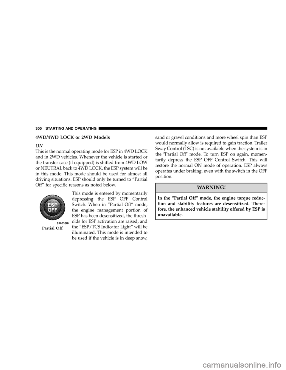
This mode is entered by momentarily
depressing the ESP OFF Control
Switch. When in ªPartial Offº mode,
the engine management portion of
ESP has been desensitized, the thresh-
olds for ESP activation are raised, and
the ªESP/TCS Indicator Lightº will be
illuminated. This mode is intended to
be used if the vehicle is in deep snow,sand or gravel conditions and more wheel spin than ESP
would normally allow is required to gain traction. Trailer
Sway Control (TSC) is not available when the system is in
the9Partial Off9mode. To turn ESP on again, momen-
tarily depress the ESP OFF Control Switch. This will
restore the normal ON mode of operation. ESP always
operates under braking, even with the switch in the OFF
position.
WARNING!
In the ªPartial Offº mode, the engine torque reduc-
tion and stability features are desensitized. There-
fore, the enhanced vehicle stability offered by ESP is
unavailable.
Partial Off
300 STARTING AND OPERATING
Page 302 of 479
NOTE:To improve the vehicle's traction when driving
with snow chains, or starting off in deep snow, sand or
gravel, it may be desirable to switch to the ªPartial Offº
mode by pressing the ESP Control Switch. Once the
situation requiring ESP to be switched to the ªPartial Offº
mode is overcome, turn ESP on by momentarily depress-
ing the ESP Control Switch. This may be done with the
vehicle in motion.
4WD LOW Range
Partial Off
This is the normal operating mode for ESP in 4WD LOW.
Whenever the vehicle is started in 4WD LOW or the
transfer case (if equipped) is shifted from 4WD LOCK or
NEUTRAL to 4WD LOW, the ESP system will be in this
mode. In 4WD LOW, ESP function is desensitized until
the vehicle reaches a speed of 30 mph (48 km/h). At 30
mph (48 km/h) the normal ESP stability function returns
and the ESP/TCS Indicator Light turns off. When thevehicle speed drops below 25 mph (40 km/h) the ESP
system goes back to Partial Off. ESP is desensitized at low
vehicle speeds in 4WD LOW so that it will not interfere
with off road driving but ESP function returns to provide
the stability feature at speeds above 30 mph (48 km/h).
The ABS is in a special Off Road mode that allows wheels
to lock at lower speeds if gravel is detected to shorten
stopping distances.
NOTE:When the vehicle is in 4WD LOW, a feature of
the ESP system remains active whether the ESP is on or
off. This feature functions similar to a limited slip differ-
ential and controls the wheel spin across an axle. If one
wheel on an axle is spinning faster than the other, the
system will apply the brake of the spinning wheel and
allow more engine torque to be applied to the wheel that
is not spinning.
STARTING AND OPERATING 301
5
Page 303 of 479
WARNING!
In the Partial Off mode, the engine torque reduction
and stability features are desensitized. Therefore, the
enhanced vehicle stability offered by ESP is
unavailable.
ESP/BAS Warning Lamp and ESP/TCS Indicator
Light
The malfunction indicator for the ESP is combined with
the BAS indicator. The yellow ESP/BAS Warning Light
and the yellow ESP/TCS Indicator Light in the instru-
ment cluster both come on when the ignition switch is
turned to the ON position. They should both go out with
the engine running. If the ESP/BAS Warning Light comes
on continuously with the engine running, a malfunction
has been detected in either the ESP or BAS system, or
both. If this light remains on after several ignition cycles,and the vehicle has been driven several miles at speeds
greater than 30 mph (48 km/h), see your authorized
dealer as soon as possible to have the problem diagnosed
and corrected.
NOTE:
²The ESP Indicator Light and the ESP/BAS Warning
Light come on momentarily each time the ignition
switch is turned ON.
²Each time the ignition is turned ON, the ESP System
will be ON even if it was turned off previously.
²The ESP Control System will make buzzing or clicking
sounds when it is active. This is normal; the sounds
will stop when ESP becomes inactive following the
maneuver that caused the ESP activation.
Trailer Sway Control (TSC)
TSC uses sensors in the vehicle to recognize a swaying
trailer and will take the appropriate actions to attempt to
302 STARTING AND OPERATING
Page 375 of 479
WARNING!
Raising the vehicle higher than necessary can make
the vehicle unstable and cause an accident. It could
slip off the jack and hurt someone near it. Raise the
vehicle only enough to remove the tire.
5. Remove the wheel nuts and pull the wheel off. Install
the spare wheel and wheel nuts with the cone shaped end
of the nuts toward the wheel. Lightly tighten the nuts. To
avoid risk of forcing the vehicle off the jack, do not fully
tighten the nuts until the vehicle has been lowered.
NOTE:Do not oil wheel studs. For chrome wheels, do
not substitute with chrome plated wheel nuts.
6. Using the wheel wrench, finish tightening the nuts in
a crisscross pattern. Correct nut tightness is 135 10 ft lbs
(183 14 N´m) dynamic torque. If in doubt about thecorrect tightness, have them checked with a torque
wrench by your authorized dealer or at a service station.WARNING!
A loose tire or jack thrown forward in a collision or
hard stop could injure someone in the vehicle. Al-
ways stow the jack, tools and the extra tire and wheel
in the places provided.
7. Remove wheel blocks. Do not install chrome or alu-
minum wheel center caps on the spare wheel. This may
result in cap damage.
8. Lower the jack to its fully closed position. Stow the
replaced tire, jack, and tools as previously described.
9. Adjust the tire pressure when possible.
NOTE:Do not oil wheel studs. For chrome wheels, do
not substitute with chrome plated wheel nuts.
374 WHAT TO DO IN EMERGENCIES
Page 409 of 479
Ensure nylon tubing in these areas has not melted or
collapsed.
Inspect all hose clamps and couplings to make sure they
are secure and no leaks are present.
NOTE:Fluids such as oil, power steering fluid, and
brake fluid are used during assembly plant operations to
ease the assembly of hoses to couplings. Therefore, oil
wetness at the hose-coupling area is not necessarily an
indication of leakage. Actual dripping of hot fluid when
systems are under pressure (during vehicle operation),
should be noted before hose is replaced based on leakage.
You are urged to use only the manufacturer's specified
hoses and clamps, or their equivalent in material and
specification, in any fuel system servicing. It is manda-
tory to replace all clamps that have been loosened or
removed during service. Care should be taken in install-
ing new clamps to ensure they are properly torqued.Positive Crankcase Ventilation (PCV) Valve
Proper operation of the crankcase ventilation system
requires that the PCV valve be free of sticking or plug-
ging because of deposits. Deposits can accumulate in the
PCV valve and passage with increasing mileage. Have
the PCV valve, hoses, and passages checked for proper
operation at the intervals specified. If the valve is
plugged or sticking, replace with a new valve ±Do not
attempt to clean the PCV valve!Check ventilating hose
for indication of damage or plugging with deposits.
Replace if necessary.
Brake System
Power Disc Brakes (Front and Rear)
Disc brakes do not require adjustment; however, several
hard stops during the break-in period are recommended
to seat the linings and wear off any foreign material.
408 MAINTAINING YOUR VEHICLE