tow CHRYSLER ASPEN 2009 2.G User Guide
[x] Cancel search | Manufacturer: CHRYSLER, Model Year: 2009, Model line: ASPEN, Model: CHRYSLER ASPEN 2009 2.GPages: 481, PDF Size: 9.28 MB
Page 151 of 481
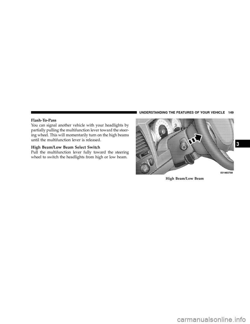
Flash-To-Pass
You can signal another vehicle with your headlights by
partially pulling the multifunction lever toward the steer-
ing wheel. This will momentarily turn on the high beams
until the multifunction lever is released.
High Beam/Low Beam Select Switch
Pull the multifunction lever fully toward the steering
wheel to switch the headlights from high or low beam.
High Beam/Low Beam
UNDERSTANDING THE FEATURES OF YOUR VEHICLE 149
3
Page 156 of 481
Adjustment
1. Position the driver seat so that you are at least 10 in
(254 mm) away from the airbag located in the center of
the steering wheel.
2. Fasten and adjust the seatbelts.
3. Move the adjustable pedal switch, located to the left of
the steering column near the parking brake release, up to
move the pedals toward the driver or down to move the
pedals away from the driver.
4. The pedalscannotbe adjusted when the vehicle is in
REVERSE or when the speed control is SET.
CAUTION!
Do not place any article under the adjustable pedals
or impede its ability to move as it may cause damage
to the pedal controls. Pedal travel may become lim-
ited if movement is stopped by an obstruction in the
adjustable pedal's path.
154 UNDERSTANDING THE FEATURES OF YOUR VEHICLE
Page 159 of 481
To Vary The Speed Setting
When the Electronic Speed Control System is ON, the
speed can be increased by pressing and holding the
RESUME/ACCEL button. When the button is released, a
new set speed will be established.
Tapping the ACCEL button once will result in a speed
increase of 1 mph (2 km/h). Each time the button is
tapped, speed increases so that tapping the button three
times will increase speed by 3 mph (4.8 km/h).
Tapping the DECEL button once will result in a speed
decrease of 1 mph (2 km/h). Each time the button is
tapped, speed will decrease. For example, tapping the
button three times will decrease the speed by 3 mph (4.8
km/h).
To decrease the speed while the Electronic Speed Control
is on, press and hold the DECEL button. Release the
button when the desired speed is reached, and the new
speed will be set.
To Accelerate For Passing
Depress the accelerator as you would normally. When the
pedal is released, the vehicle will return to the set speed.
NOTE:When driving uphill, at elevations above 2,000 ft
(610 m), or when the vehicle is heavily loaded (especially
when towing) the vehicle may slow below the SET speed.
If the vehicle speed drops below 25 mph (40 km/h), the
Electronic Speed Control will automatically disengage. If
this happens, you can push down on the accelerator
pedal to maintain the desired speed.
Vehicles equipped with an automatic transmission may
exhibit several downshifts under the above conditions.
To reduce the frequency of the downshifts and to im-
prove vehicle performance, it is advisable to lock out
OVERDRIVE by pressing the TOW/HAUL button lo-
cated at the end of the shift lever.
UNDERSTANDING THE FEATURES OF YOUR VEHICLE 157
3
Page 163 of 481
WARNING!
²Drivers must be careful when backing up, even
when using the Rear Park Assist system. Always
check carefully behind your vehicle, look behind
you, and be sure to check for pedestrians, animals,
other vehicles, obstructions, and blind spots be-
fore backing up. You are responsible for safety and
must continue to pay attention to your surround-
ings. Failure to do so can result in serious injury or
death.
(Continued)
WARNING! (Continued)
²Before using the Rear Park Assist system, it is
strongly recommended that the ball mount and
hitch ball assembly is disconnected from the ve-
hicle when the vehicle is not used for towing.
Failure to do so can result in injury or damage to
vehicles or obstacles because the hitch ball will be
much closer to the obstacle than the rear fascia
when the warning display turns the red LEDs ON.
Also, the sensors could detect the ball mount and
hitch ball assembly, depending on its size and
shape, giving a false indication that an obstacle is
behind the vehicle.
UNDERSTANDING THE FEATURES OF YOUR VEHICLE 161
3
Page 164 of 481
CAUTION!
²The Rear Park Assist system is only a parking aid
and it is unable to recognize every obstacle, in-
cluding small obstacles. Parking curbs might be
temporarily detected or not detected at all. Ob-
stacles located above or below the sensors will not
be detected when they are in close proximity.
²The vehicle must be driven slowly when using the
Rear Park Assist system to be able to stop in time
when the obstacle is detected. It is recommended
that the driver look over his/her shoulder when
using the Rear Park Assist system.
NOTE:
²Ensure that the rear bumper is free of dirt and debris
to keep the system operating properly.
²Jackhammers, large trucks, and other vibrations could
affect the performance of the system.
Enable/Disable The Rear Park Assist System
There are times when you may want to disable the Rear
Park Assist system, such as when towing a trailer.
The system can be turned ON or OFF through the
Electronic Vehicle Information (EVIC) ± if equipped.
Refer to ªPersonal Settings (Customer Programmable
Features)º under ªOverhead Console with Electronic
Vehicle Information Center (EVIC) ± If Equippedº in
Section 3.
Service The Rear Park Assist System
When the Rear Park Assist System is defective, the EVIC
will display the ªSERVICE PARK ASSIST SYSTEMº
message along with a single chime once per ignition
cycle. Refer to ªElectronic Vehicle Information Center
(EVIC)º in Section 3 of this manual. The Park Assist
display will also light the red led's indicating a problem.
Under this condition the Rear Park Assist System will not
operate.
162 UNDERSTANDING THE FEATURES OF YOUR VEHICLE
Page 197 of 481
To remove the cargo management system from the ve-
hicle, pull the right-hand side of the organizer toward
you so that the right pin slides out of the slot in the
vehicle. Push the organizer to the right and lift out of the
vehicle.
REAR WINDOW FEATURES
Rear Window Wiper/Washer
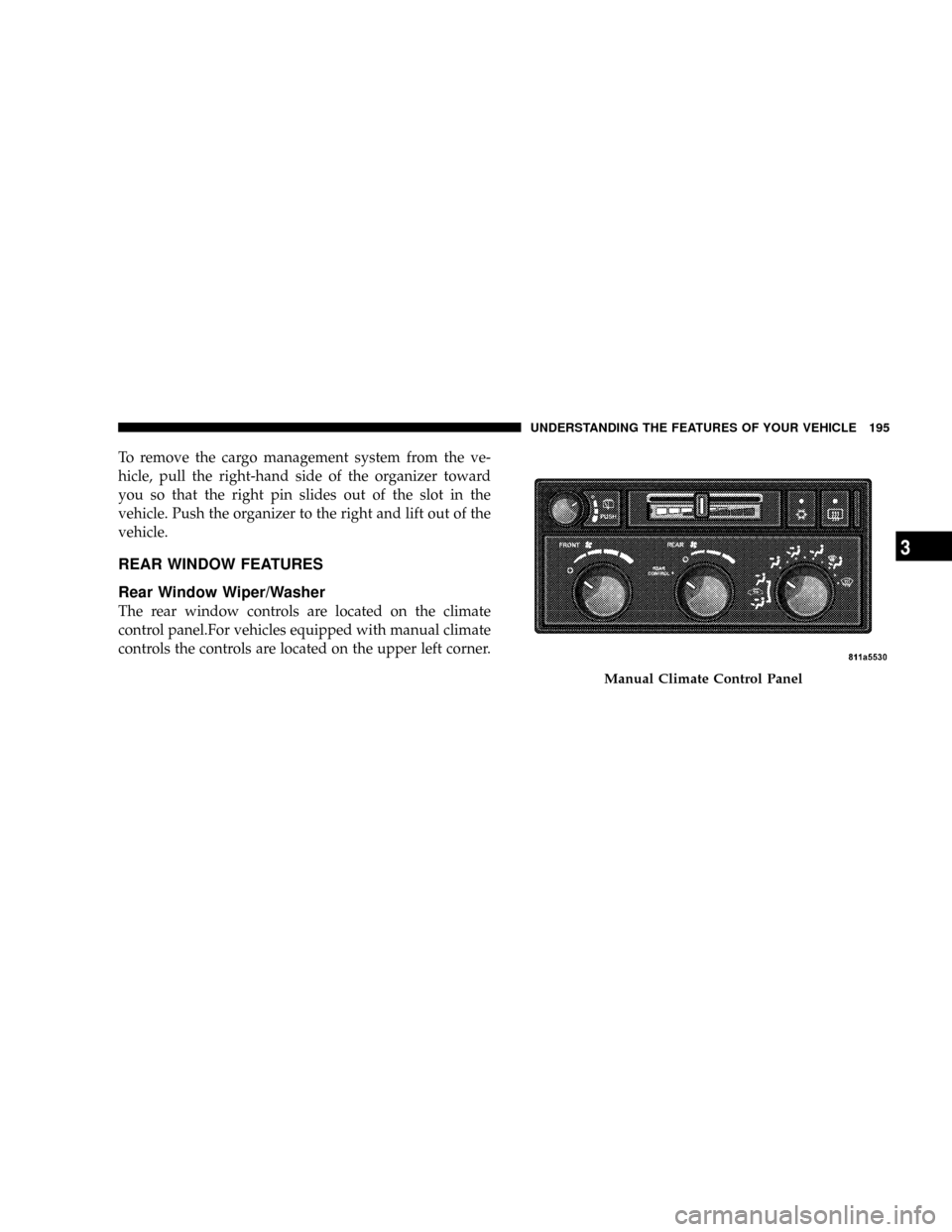
The rear window controls are located on the climate
control panel.For vehicles equipped with manual climate
controls the controls are located on the upper left corner.
Manual Climate Control Panel
UNDERSTANDING THE FEATURES OF YOUR VEHICLE 195
3
Page 206 of 481
INSTRUMENT CLUSTER DESCRIPTION
1. Fuel Gauge
The fuel gauge shows level of fuel in the tank when
ignition switch is in the ON position.
2. Temperature Gauge
The temperature gauge shows engine coolant tempera-
ture. Any reading within the normal range indicates that
the engine cooling system is operating satisfactorily. The
gauge pointer will likely indicate a higher temperature
when driving in hot weather, up mountain grades, or
when towing a trailer. It should not be allowed to exceed
the upper limits of the normal operating range.
CAUTION!
Do not leave your vehicle unattended with the en-
gine running as you would not be able to react to the
temperature indicator if the engine overheats.The gauge pointer will remain near its last reading when
the engine is turned off. It will return to a true reading
when the engine is restarted.
3. Turn Signal Indicators
When a turn signal is activated, a right-pointing or
left-pointing arrow lights up and flashes to indicate the
direction of the turn. These indicators also indicate
proper operation of the front and rear turn signal lights.
If either indicator flashes at a faster rate than normal,
check for a defective bulb. If either indicator fails to light
up when the lever is moved, check for a defective fuse or
turn signal LED. A single chime is activated when the
left/right turn signal is left on with the engine RPM
vehicle speed greater than 15 mph (24 km/h) for more
than one mile.
4. Low Fuel Warning Light
This indicator lights when the fuel gauge reads
1/16 of a tank or less.
204 UNDERSTANDING YOUR INSTRUMENT PANEL
Page 212 of 481
button has been pressed or ESP is only partially available
caused by lack of engine management or brake thermal
model.
19. Transmission Temperature Indicator
This light indicates that there is excessive trans-
mission fluid temperature that might occur
with severe usage, such as trailer towing. If this
light comes on, stop the vehicle and run the
engine at idle or faster, with the transmission in NEU-
TRAL until the light goes off.
20. Electronic Throttle Control (ETC)
This light informs you of a problem with the
Electronic Throttle Control (ETC) system. If a
problem is detected, the light will come on
while the engine is running. If the light remains
lit with the engine running your vehicle will usually be
drivable, however, see an authorized dealer for service as
soon as possible. If the light is flashing when the engineis running, immediate service is required and you may
experience reduced performance, an elevated/rough idle
or engine stall and your vehicle may require towing. The
light will come on when the ignition is first turned on
and remain on for 15 seconds as a bulb check. If the light
does not come on during starting, have the system
checked by an authorized dealer.
21. Brake System Warning Light
This light monitors various brake functions,
including brake fluid level and parking brake
application. If the brake light turns on, it may
indicate that the parking brake is applied, that
the brake fluid level is low, or that there is a problem with
the anti-lock brake system reservoir.
If the light remains on when the parking brake has been
disengaged, and the fluid level is at the full mark on the
master cylinder reservoir, it indicates a possible brake
hydraulic system malfunction or a problem with the
210 UNDERSTANDING YOUR INSTRUMENT PANEL
Page 215 of 481
If the MIL comes on and remains on while driving, it
suggests a potential engine control problem and the need
for system service. See an authorized dealer as soon as
possible.
Although your vehicle will usually be drivable and not
need towing, see an authorized dealer for service as soon
as possible.
CAUTION!
Prolonged driving with the MIL on could cause
damage to the engine control system. It also could
affect fuel economy and driveability.
If the MIL is flashing, severe catalytic converter
damage and power loss will soon occur. Immediate
service is required. See an authorized dealer for
service immediately.24. Tire Pressure Monitoring Telltale Light
Each tire, including the spare (if provided),
should be checked monthly when cold and
inflated to the inflation pressure recommended
by the vehicle manufacturer on the vehicle
placard or tire inflation pressure label. (If your vehicle
has tires of a different size than the size indicated on the
vehicle placard or tire inflation pressure label, you should
determine the proper tire inflation pressure for those
tires.)
UNDERSTANDING YOUR INSTRUMENT PANEL 213
4
Page 218 of 481
29. TOW/HAUL
The TOW/HAUL button is located at the end of the shift
lever. This light will illuminate when the TOW/HAUL
button has been selected.
30. 4LOW Indicator
Indicates the transfer case is in 4LOW position.
31. Odometer / Trip Odometer Button
Press this button to toggle between the odometer and the
trip odometer display. Holding the button in resets the
trip odometer reading.
SETTING THE ANALOG CLOCK
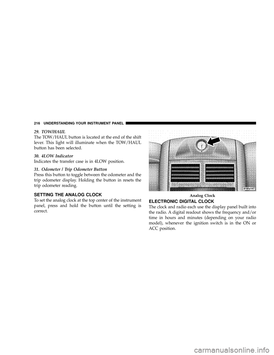
To set the analog clock at the top center of the instrument
panel, press and hold the button until the setting is
correct.ELECTRONIC DIGITAL CLOCK
The clock and radio each use the display panel built into
the radio. A digital readout shows the frequency and/or
time in hours and minutes (depending on your radio
model), whenever the ignition switch is in the ON or
ACC position.
Analog Clock
216 UNDERSTANDING YOUR INSTRUMENT PANEL