service CHRYSLER CARAVAN 2000 Service Manual
[x] Cancel search | Manufacturer: CHRYSLER, Model Year: 2000, Model line: CARAVAN, Model: CHRYSLER CARAVAN 2000Pages: 436, PDF Size: 3.4 MB
Page 5 of 436

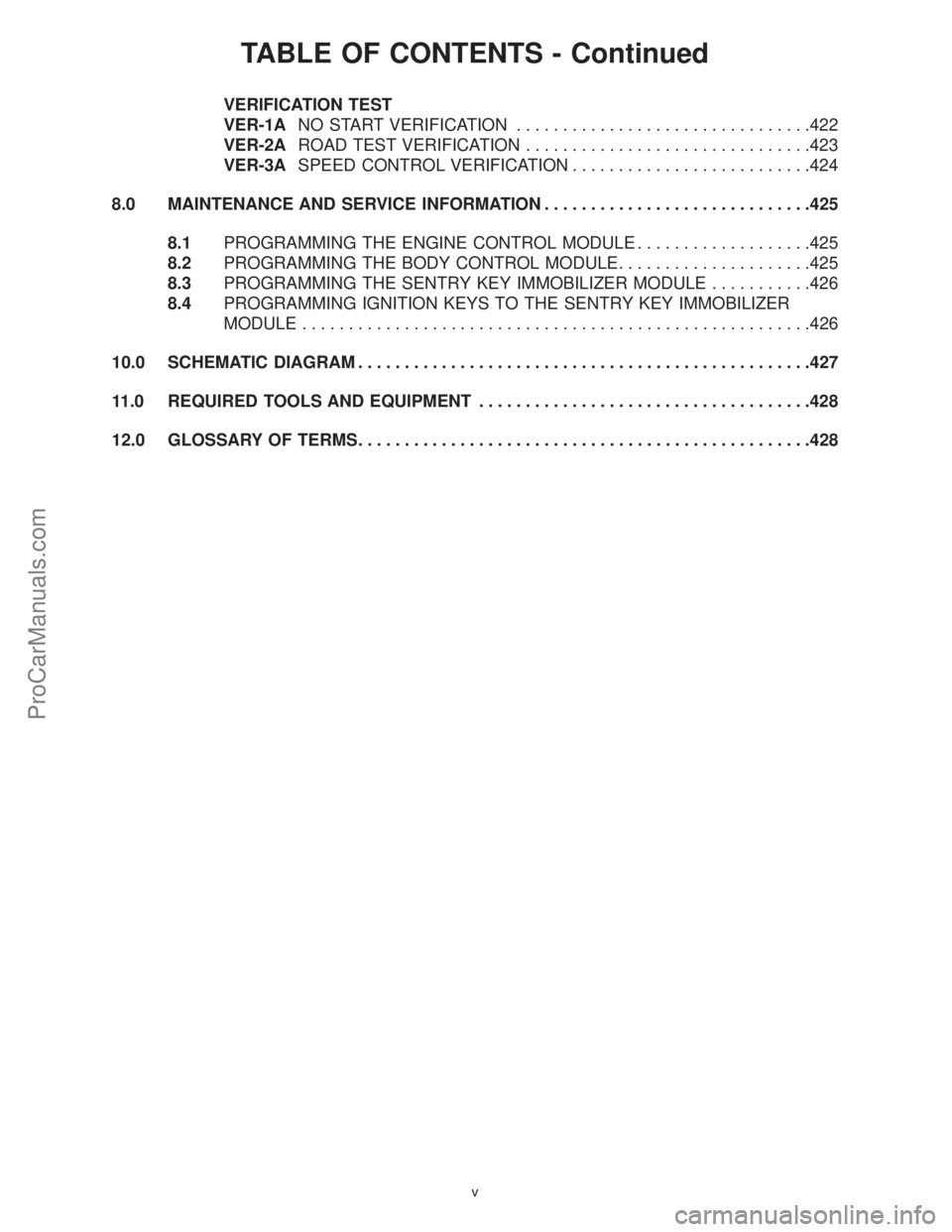
TABLE OF CONTENTS - Continued
VERIFICATION TEST
VER-1ANO START VERIFICATION................................422
VER-2AROAD TEST VERIFICATION...............................423
VER-3ASPEED CONTROL VERIFICATION..........................424
8.0 MAINTENANCE AND SERVICE INFORMATION.............................425
8.1PROGRAMMING THE ENGINE CONTROL MODULE...................425
8.2PROGRAMMING THE BODY CONTROL MODULE.....................425
8.3PROGRAMMING THE SENTRY KEY IMMOBILIZER MODULE...........426
8.4PROGRAMMING IGNITION KEYS TO THE SENTRY KEY IMMOBILIZER
MODULE.......................................................426
10.0 SCHEMATIC DIAGRAM.................................................427
11.0 REQUIRED TOOLS AND EQUIPMENT....................................428
12.0 GLOSSARY OF TERMS.................................................428
v
ProCarManuals.com
Page 7 of 436

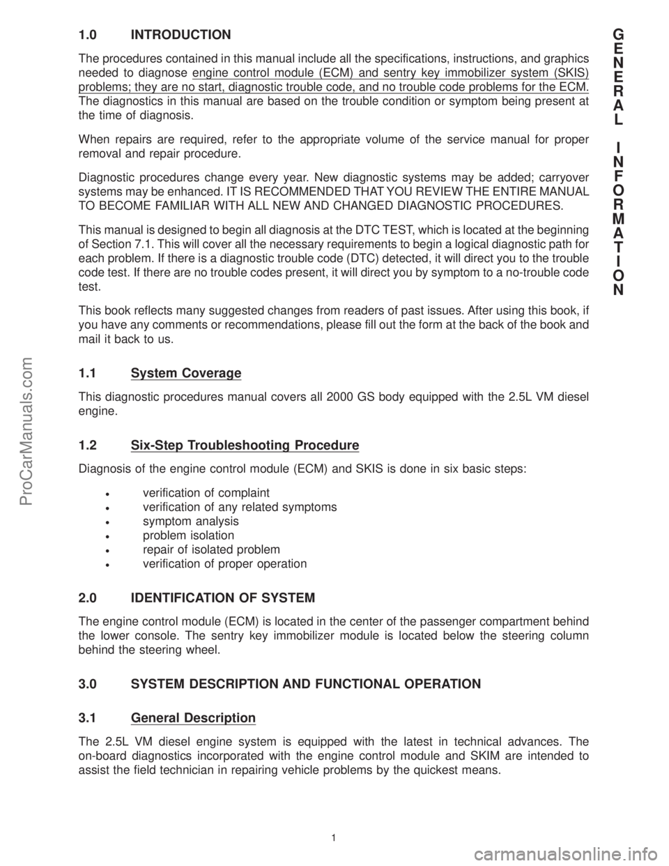
1.0 INTRODUCTION
The procedures contained in this manual include all the specifications, instructions, and graphics
needed to diagnose engine control module (ECM) and sentry key immobilizer system (SKIS)
problems; they are no start, diagnostic trouble code, and no trouble code problems for the ECM.
The diagnostics in this manual are based on the trouble condition or symptom being present at
the time of diagnosis.
When repairs are required, refer to the appropriate volume of the service manual for proper
removal and repair procedure.
Diagnostic procedures change every year. New diagnostic systems may be added; carryover
systems may be enhanced. IT IS RECOMMENDED THAT YOU REVIEW THE ENTIRE MANUAL
TO BECOME FAMILIAR WITH ALL NEW AND CHANGED DIAGNOSTIC PROCEDURES.
This manual is designed to begin all diagnosis at the DTC TEST, which is located at the beginning
of Section 7.1. This will cover all the necessary requirements to begin a logical diagnostic path for
each problem. If there is a diagnostic trouble code (DTC) detected, it will direct you to the trouble
code test. If there are no trouble codes present, it will direct you by symptom to a no-trouble code
test.
This book reflects many suggested changes from readers of past issues. After using this book, if
you have any comments or recommendations, please fill out the form at the back of the book and
mail it back to us.
1.1 System Coverage
This diagnostic procedures manual covers all 2000 GS body equipped with the 2.5L VM diesel
engine.
1.2 Six-Step Troubleshooting Procedure
Diagnosis of the engine control module (ECM) and SKIS is done in six basic steps:
²verification of complaint
²verification of any related symptoms
²symptom analysis
²problem isolation
²repair of isolated problem
²verification of proper operation
2.0 IDENTIFICATION OF SYSTEM
The engine control module (ECM) is located in the center of the passenger compartment behind
the lower console. The sentry key immobilizer module is located below the steering column
behind the steering wheel.
3.0 SYSTEM DESCRIPTION AND FUNCTIONAL OPERATION
3.1 General Description
The 2.5L VM diesel engine system is equipped with the latest in technical advances. The
on-board diagnostics incorporated with the engine control module and SKIM are intended to
assist the field technician in repairing vehicle problems by the quickest means.
G
E
N
E
R
A
L
I
N
F
O
R
M
A
T
I
O
N
1
ProCarManuals.com
Page 11 of 436

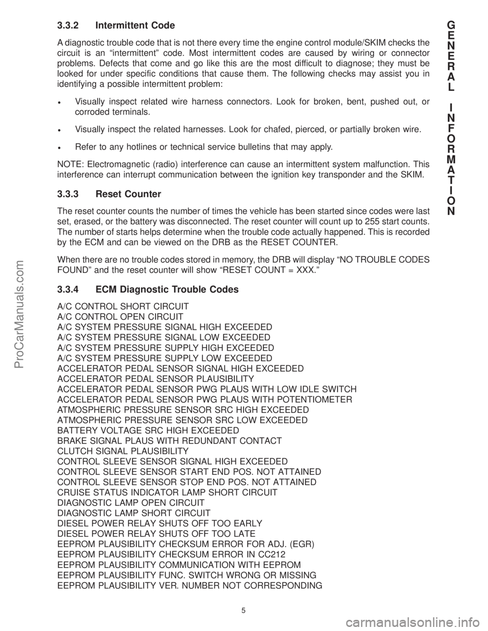
3.3.2 Intermittent Code
A diagnostic trouble code that is not there every time the engine control module/SKIM checks the
circuit is an ªintermittentº code. Most intermittent codes are caused by wiring or connector
problems. Defects that come and go like this are the most difficult to diagnose; they must be
looked for under specific conditions that cause them. The following checks may assist you in
identifying a possible intermittent problem:
²Visually inspect related wire harness connectors. Look for broken, bent, pushed out, or
corroded terminals.
²Visually inspect the related harnesses. Look for chafed, pierced, or partially broken wire.
²Refer to any hotlines or technical service bulletins that may apply.
NOTE: Electromagnetic (radio) interference can cause an intermittent system malfunction. This
interference can interrupt communication between the ignition key transponder and the SKIM.
3.3.3 Reset Counter
The reset counter counts the number of times the vehicle has been started since codes were last
set, erased, or the battery was disconnected. The reset counter will count up to 255 start counts.
The number of starts helps determine when the trouble code actually happened. This is recorded
by the ECM and can be viewed on the DRB as the RESET COUNTER.
When there are no trouble codes stored in memory, the DRB will display ªNO TROUBLE CODES
FOUNDº and the reset counter will show ªRESET COUNT = XXX.º
3.3.4 ECM Diagnostic Trouble Codes
A/C CONTROL SHORT CIRCUIT
A/C CONTROL OPEN CIRCUIT
A/C SYSTEM PRESSURE SIGNAL HIGH EXCEEDED
A/C SYSTEM PRESSURE SIGNAL LOW EXCEEDED
A/C SYSTEM PRESSURE SUPPLY HIGH EXCEEDED
A/C SYSTEM PRESSURE SUPPLY LOW EXCEEDED
ACCELERATOR PEDAL SENSOR SIGNAL HIGH EXCEEDED
ACCELERATOR PEDAL SENSOR PLAUSIBILITY
ACCELERATOR PEDAL SENSOR PWG PLAUS WITH LOW IDLE SWITCH
ACCELERATOR PEDAL SENSOR PWG PLAUS WITH POTENTIOMETER
ATMOSPHERIC PRESSURE SENSOR SRC HIGH EXCEEDED
ATMOSPHERIC PRESSURE SENSOR SRC LOW EXCEEDED
BATTERY VOLTAGE SRC HIGH EXCEEDED
BRAKE SIGNAL PLAUS WITH REDUNDANT CONTACT
CLUTCH SIGNAL PLAUSIBILITY
CONTROL SLEEVE SENSOR SIGNAL HIGH EXCEEDED
CONTROL SLEEVE SENSOR START END POS. NOT ATTAINED
CONTROL SLEEVE SENSOR STOP END POS. NOT ATTAINED
CRUISE STATUS INDICATOR LAMP SHORT CIRCUIT
DIAGNOSTIC LAMP OPEN CIRCUIT
DIAGNOSTIC LAMP SHORT CIRCUIT
DIESEL POWER RELAY SHUTS OFF TOO EARLY
DIESEL POWER RELAY SHUTS OFF TOO LATE
EEPROM PLAUSIBILITY CHECKSUM ERROR FOR ADJ. (EGR)
EEPROM PLAUSIBILITY CHECKSUM ERROR IN CC212
EEPROM PLAUSIBILITY COMMUNICATION WITH EEPROM
EEPROM PLAUSIBILITY FUNC. SWITCH WRONG OR MISSING
EEPROM PLAUSIBILITY VER. NUMBER NOT CORRESPONDING
G
E
N
E
R
A
L
I
N
F
O
R
M
A
T
I
O
N
5
ProCarManuals.com
Page 23 of 436

4.8 Lamps and Indicators
The ªCruiseº lamp is controlled by the Body Control Module. The Diagnostic/Glow Plug lamp is
controlled by the Engine Control Module. The ªAlarm Setº lamp is controlled by the SKIM.
5.0 DISCLAIMERS, SAFETY, WARNINGS
5.1 Disclaimers
All information, illustrations, and specifications contained in this manual are based on the latest
information available at the time of publication. The right is reserved to make changes at any time
without notice.
5.2 Safety
5.2.1 Technician Safety Information
WARNING!!Engines produce carbon monoxide that is odorless, causes slower reaction time,
and can lead to serious injury. When the engine is operating, keep service areas WELL
VENTILATED or attach the vehicle exhaust system to the shop exhaust removal system.
Set the parking brake and block the wheels before testing or repairing the vehicle. It is especially
important to block the wheels on front-wheel drive vehicles; the parking brake does not hold the
drive wheels.
When servicing a vehicle, always wear eye protection, and remove any metal jewelry such as
watchbands or bracelets that might make an inadvertent electrical contact.
When diagnosing a powertrain system problem, it is important to follow approved procedures
where applicable. These procedures can be found in the service manual. Following these
procedures is very important to the safety of individuals performing diagnostic tests.
5.2.2 Vehicle Preparation for Testing
Make sure the vehicle being tested has a fully charged battery. If it does not, false diagnostic
codes or error messages may occur.
5.2.3 Servicing Sub-Assemblies
Some components of the powertrain system are intended to be serviced in assembly only.
Attempting to remove or repair certain system sub-components may result in personal injury
and/or improper system operation. Only those components with approved repair and installation
procedures in the service manual should be serviced.
5.2.4 DRBIIITSafety Information
WARNING: Exceeding the limits of the DRB multimeter is dangerous. It can expose you to
serious or possibly fatal injury. Carefully read and understand the cautions and the
specification limits.
²Follow the vehicle manufacturer's service specifications at all times.
²Do not use the DRB if it has been damaged.
²Do not use the test leads if the insulation is damaged or if metal is exposed.
²To avoid electrical shock, do not touch the test leads, tips, or the circuit being tested.
G
E
N
E
R
A
L
I
N
F
O
R
M
A
T
I
O
N
17
ProCarManuals.com
Page 273 of 436

TEST TC-86AREPAIRING - TIMING GOVERNING POSITIVE GOVERNOR DEVIATION
Perform TEST DTC Before Proceeding
*Perform Verification TEST VER-2A. **Check connectors - Clean / repair as necessary.
NOTE: INCORRECT HAS THE TIMING VERIFY CORRECT
START TEST INJECTION PUMP CHAIN, TIMING YES VALVE TIMING AND
TC-86A. TIMING CAN CAUSE GEARS OR INJECTION INJECTION PUMP
THIS TROUBLE CODE. PUMP BEEN SERVICED TIMING BEFORE
RECENTLY? CONTINUING.
NO
WITH THE DRB, ATTEMPT TO START READ CODES. DOES
ERASE CODES. ENGINE AND THE DRB DISPLAY YES CONTINUE TEST
INCREASE ENGINE "TIMING GOVERNING TC-86A ON THE
TURN IGNITION OFF SPEED ABOVE 1000 POSITIVE GOVERNOR NEXT PAGE.
FOR 10 SECONDS. RPM. DEVIATION"?
NO
USE THE SCHEMATIC AS DOES THE DRB REPAIR THE HARNESS
A GUIDE AND WIGGLE MONITOR THE DRB DISPLAY "TIMING YES OR CONNECTOR THAT
THE SENSOR CONNECTOR DISPLAY. GOVERNING POSITIVE CAUSED THE CODE TO
& HARNESS. GOVERNOR SET.*
FIG.1 DEVIATION"?
NO
AT THIS TIME, THE USING THE
CONDITION REQUIRED SCHEMATIC AS A WERE ANY PROBLEMS YES REPAIR AS
TO SET THE CODE IS GUIDE, INSPECT THE FOUND? NECESSARY.*
NOT PRESENT. WIRING AND
FIG.2 CONNECTORS.
NO
REFER TO GENERAL
INFORMATION 3.3.2 YES
FOR ADDITIONAL TEST COMPLETE.*
INFORMATION ON
INTERMITTENT CODES.
T
R
O
U
B
L
E
C
O
D
E
T
E
S
T
S
267
ProCarManuals.com
Page 328 of 436

TEST NTC-1ANO TROUBLE CODE TEST MENU
First, check all Technical Service Bulletins that relate to this driveability problem. Perform corrective
actions if indicated; otherwise continue.
1.NO TROUBLE CODE COMPLETE TEST(non-monitored and monitored circuits)
PerformNTC-2AthroughNTC-13Ain sequence until the driveability problem is found.
NO TROUBLE CODE MENU
CHECKING GLOW PLUG OPERATION.........................................NTC-2A
CHECKING FUEL INJECTION PUMP CIRCUITS.................................NTC-3A
CHECKING THE PCM POWER AND GROUND CIRCUITS.........................NTC-4A
CHECKING ENGINE COOLANT SENSOR CALIBRATION..........................NTC-5A
CHECKING ACCELERATOR PEDAL SENSOR CALIBRATION......................NTC-6A
CHECKING BOOST PRESSURE SENSOR CALIBRATION.........................NTC-7A
CHECKING FUEL TEMPERATURE SENSOR CALIBRATION.......................NTC-8A
CHECKING EGR SYSTEM...................................................NTC-9A
CHECKING THE FUEL HEATER.............................................NTC-10A
CHECKING RADIATOR FAN OPERATION.....................................NTC-11A
CHECKING THE ENGINE MECHANICAL SYSTEMS.............................NTC-12A
CHECKING THE TURBOCHARGER..........................................NTC-13A
2.NO TROUBLE CODE QUICK INDIVIDUAL TEST(individual test only)
If you suspect any of the above items to be the cause of the vehicle's driveability problem, perform
the associated test(s) individually.Return to No Trouble Code Menu if driveability problem still
exists, or perform No Trouble Code Complete Test.
3.NO TROUBLE CODE QUICK SYMPTOM TEST(symptom test only)
Symptom checks cannot be used properly unless the driveability problem characteristic actually
happens while the vehicle is being tested. To reduce diagnostic time, ensure that DTC TEST and
appropriate GENERAL INFORMATION sections have been reviewed before attempting to diagnose
a symptom.
Select the symptom that most accurately describes the vehicle's driveability problem and then
perform the test routine that pertains to this symptom. Perform each routine test in sequence until
the problem is found. For definitions, see Section 12.0 in the GENERAL INFORMATION section in
this manual.
NOTE:For all component locations seeGeneral Information Section 4.0in this manual.
N
O
T
R
O
U
B
L
E
C
O
D
E
T
E
S
T
S
322
ProCarManuals.com
Page 331 of 436

TEST NTC-2ACHECKING GLOW PLUG OPERATION
Perform TEST NTC-1A Before Proceeding
*Perform Verification TEST VER-2A. **Check connectors - Clean / repair as necessary.
THE 2.5L DIESEL GLOW PLUG RELAY #1 GLOW PLUG RELAY #2
START TEST ENGINE UTILIZES SUPPLIES POWER TO SUPPLIES POWER TO
NTC-2A. TWO GLOW PLUG THE GLOW PLUGS IN THE GLOW PLUGS IN
RELAYS... CYLINDERS #1 & #4. CYLINDERS #2 & #3.
PERFORM THIS TEST
ON GLOW PLUG RELAY
#1 THEN REPEAT TURN IGNITION OFF.
TEST FOR GLOW PLUG
RELAY #2.
DISCONNECT EACH KEY ON. USING THE
GLOW PLUG HARNESS DRB, ACTUATE THE
CONNECTOR. GLOW PLUG RELAY.
USING A TEST
LIGHT, PROBE THE DOES THE TEST NO TEST NTC-2A
APPROPRIATE GLOW LIGHT FLASH ON AND CONTINUED ON
PLUG HARNESS CONN. OFF? THE NEXT PAGE.
FIG.1 AND 2
YES
GLOW PLUG CIRCUITRY
OK. REFER TO SERVICE
MANUAL TO CHECK GLOW TEST COMPLETE.*
PLUG OPERATION.
N
O
T
R
O
U
B
L
E
C
O
D
E
T
E
S
T
S
325
ProCarManuals.com
Page 373 of 436

TEST NTC-12ACHECKING THE ENGINE MECHANICAL SYSTEMS
Perform TEST NTC-1A Before Proceeding
At this point in the diagnostic test procedure, you have determined that all of theengine electrical
systemsare operating as designed; therefore, theyare not the cause of the driveability problem.
The following additional items should be checked as possible mechanical causes of the problem.
1. ENGINE VALVE TIMING- must be within specifications
2. ENGINE COMPRESSION- must be within specifications
3. CAMSHAFT LOBES- check for abnormal wear
4. ENGINE SPEED SENSOR PICK-UP- check flywheel slots for debris/deterioration
5. ENGINE EXHAUST SYSTEM- must be free of any restrictions
6. ENGINE DRIVE SPROCKET- must be properly positioned
7. POWER BRAKE BOOSTER- no internal vacuum leaks
8. FUEL- must be free of contamination
9. FUEL INJECTOR- plugged or restricted injector
10. FUEL INJECTION PUMP- must be properly timed
NOTE:Always look for any Technical Service Bulletins that may relate to the problem.
N
O
T
R
O
U
B
L
E
C
O
D
E
T
E
S
T
S
367
ProCarManuals.com
Page 403 of 436

TEST NS-1ACONTINUED - REPAIRING A NO CRANK CONDITION
*Perform Verification TEST VER-1A. **Check connectors - Clean / repair as necessary.
TEST NS-1A
CONTINUED FROM DID THE STARTER YES CONTINUE TEST
THE PREVIOUS MOTOR CRANK THE NS-1A ON THE
PAGE. ENGINE? NEXT PAGE.
NO
DID THE STARTER
YES SOLENOID CLICK NO DISCONNECT THE
WHEN THE JUMPER JUMPER WIRE.
WIRE WAS
CONNECTED?
USING AN OHMMETER, DISCONNECT STARTER
MEASURE THE RELAY OUTPUT WIRE
STARTER RELAY FROM THE STARTER
OUTPUT CIRCUIT. SOLENOID.**
FIG.1 FIG.2
IS THE RESISTANCE NO REPAIR OPEN
BELOW 5.0 OHMS? STARTER RELAY
OUTPUT CKT.*
YES
CHECK THE BATTERY DID EITHER BATTERY
REINSTALL STARTER CABLES FOR HIGH CIRCUIT HAVE A YES REPAIR THE BATTERY
RELAY. RESISTANCE. (USE VOLTAGE DROP CIRCUIT FOR HIGH
SERVICE MANUAL GREATER THAN 0.2 RESISTANCE.*
PROCEDURE) VOLT?
NO
ATTEMPT TO
MANUALLY ROTATE IS THE CRANKSHAFT NO REPAIR ENGINE
THE CRANKSHAFT 360 ABLE TO ROTATE 360 MECHANICAL PROBLEM
DEGREES. DEGREES? AS NECESSARY.*
YES
REPLACE THE
STARTER MOTOR.*
N
O
S
T
A
R
T
T
E
S
T
S
397
ProCarManuals.com
Page 419 of 436

TEST NS-3ACONTINUED - REPAIRING - NO START
*Perform Verification TEST VER-1A. **Check connectors - Clean / repair as necessary.
TEST NS-3A INSPECT ALL FUEL
CONTINUED FROM LINES FOR ARE ANY PROBLEMS YES REPAIR AS
THE PREVIOUS RESTRICTIONS LEAKS EVIDENT? NECESSARY.*
PAGE. OR OTHER PROBLEMS.
NO
REFER TO THE CHECK FUEL INJECTION
SERVICE MANUAL AND IS THE FUEL YES PUMP TIMING. CHECK
PERFORM THE FUEL PRESSURE OK? FUEL SUPPLY FOR
SYSTEM PRESSURE CONTAMINATION SUCH
TEST. AS WATER.*
NO
CHECK THE FUEL
PUMP DRIVE. IF OK,
REPLACE THE FUEL
INJECTION PUMP
ASSEMBLY.*
N
O
S
T
A
R
T
T
E
S
T
S
413
ProCarManuals.com