light CHRYSLER CARAVAN 2002 Owners Manual
[x] Cancel search | Manufacturer: CHRYSLER, Model Year: 2002, Model line: CARAVAN, Model: CHRYSLER CARAVAN 2002Pages: 2399, PDF Size: 57.96 MB
Page 557 of 2399

(5) Grab the latch assembly and unhook the key
cylinder link rod from the key cylinder (Fig. 13).
(6) Place the latch assembly on a bench and locate
the three wires leading from the actuator portion of
the latch assembly.
(7) Disengage the main connector retaining push
pins from the latch actuator housing.
(8) Back the three wires out of the main latch elec-
trical connector. Refer to the wiring section of the
service manual for detailed instructions.
(9) Flip the latch assembly over and remove the
latch actuator retaining screw(s).
(10) Remove the latch actuator from the latch
assembly.
INSTALLATION
(1) Install the latch actuator on the latch assem-
bly.
(2) Install the three latch actuator retaining
screws. Torque the screws to 4 in. lbs.
(3) Install the three wires in the main latch elec-
trical connector. Refer to the wiring section of the
service manual for detailed instructions.
NOTE: Be certain wires are reinstalled in the correct
wire cavities. Failure to do so could result in dam-
age to the latch actuator. Refer to Wiring Diagrams
if previous notes were not made.
(4) Secure the main connector retaining push pins
on the latch actuator housing.
(5) Grab the latch assembly and hook the key cyl-
inder link rod on the key cylinder.
(6) Position the latch and install the three latch
retaining bolts. Torque to 10 N´m (90 in. lbs.).
(7) Connect the power latch electrical connector.
(8) Install the lower liftgate trim panel. Refer to
Body for the procedure.
(9) Connect the negative battery cable.
EXTERIOR HANDLE SWITCH
DESCRIPTION
Vehicles equipped with a power liftgate or power
locks utilize a exterior handle switch. The exterior
handle switch is a electronic release switch mounted
to the rear license plate lamp housing assembly,
located just above the license plate. This switch con-
trols the power liftgate release function and is also
capable of reversing the power liftgate when it is in
motion. A full power open cycle cannot be performed
using this switch, only one of the power open com-
mand switches (key fob and overhead console
mounted) can be used to perform a full power open
cycle.The exterior handle switch is a serviceable compo-
nent. Consult your MoparŸ parts catalog for a spe-
cific part number.
OPERATION
When the exterior handle switch is depressed, with
the liftgate in the closed position. A message is sent
to the Body Control Module (BCM). The Body Con-
trol Module then sends a signal to the power liftgate
control module via the J1850 PCI data bus circuit.
The power liftgate control module then sends a sig-
nal to the power latch mounted actuator, which
moves the liftgate from the primary closed and
latched position to the open and movable position. If
the liftgate is not pulled open once the latch releases
within a few seconds, the latch will cinch closed
again.
REMOVAL
(1) Disconnect and isolate the negative battery
cable.
(2) Open the liftgate and remove the liftgate trim
panel. Refer to the Body section of the service man-
ual for the procedure.
(3) Remove the rear lamp bar assembly from the
vehicle. Refer to the Body section of the service man-
ual for the procedure.
(4) Locate the two wires going to the exterior han-
dle switch. Cut the tie strap and trace the wires to
the large electrical connector and back the wires out
of the large connector and through the grommet.
Refer to the Wiring section of the service manual for
detailed instructions.
(5) Depress the two exterior handle switch retain-
ing tabs and roll the switch out of the light bar
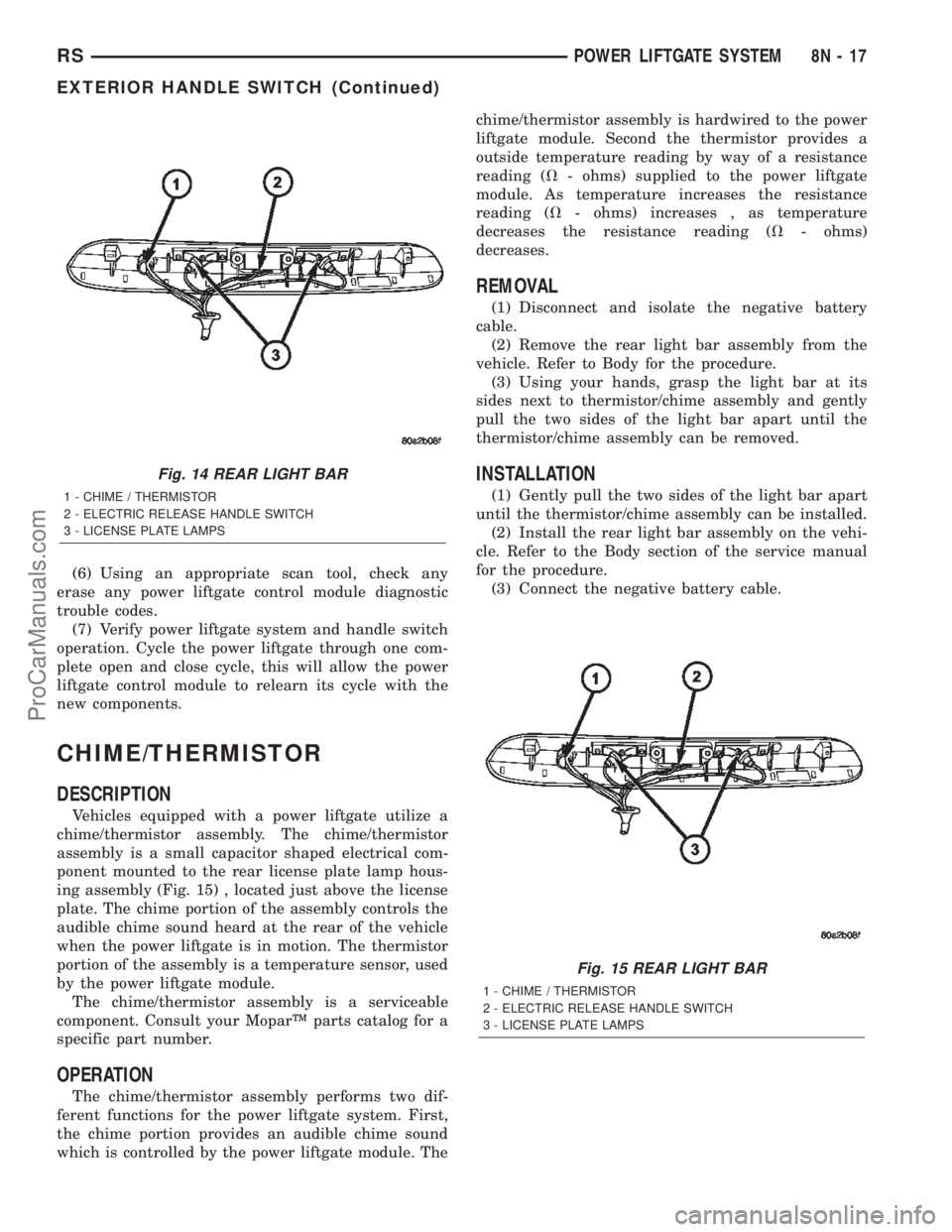
assembly (Fig. 14).
INSTALLATION
(1) Install the handle switch in the light bar
assembly.
(2) Locate the two wires going to the exterior han-
dle switch. Install the wires through the grommet
and in the large connector. Secure with a tie strap.
Refer to the Wiring section of the service manual for
detailed instructions.
NOTE: Be certain wires are reinstalled in the correct
wire cavities. Failure to do so could result in dam-
age to the handle switch. Refer to Wiring Diagrams
if previous notes were not made.
(3) Install the rear light bar. Refer to the Body sec-
tion of the service manual for the procedure.
(4) Install the liftgate trim panel. Refer to the
Body section of the service manual for the procedure.
(5) Connect the negative battery cable.
8N - 16 POWER LIFTGATE SYSTEMRS
LATCH ACTUATOR (Continued)
ProCarManuals.com
Page 558 of 2399
(6) Using an appropriate scan tool, check any
erase any power liftgate control module diagnostic
trouble codes.
(7) Verify power liftgate system and handle switch
operation. Cycle the power liftgate through one com-
plete open and close cycle, this will allow the power
liftgate control module to relearn its cycle with the
new components.
CHIME/THERMISTOR
DESCRIPTION
Vehicles equipped with a power liftgate utilize a
chime/thermistor assembly. The chime/thermistor
assembly is a small capacitor shaped electrical com-
ponent mounted to the rear license plate lamp hous-
ing assembly (Fig. 15) , located just above the license
plate. The chime portion of the assembly controls the
audible chime sound heard at the rear of the vehicle
when the power liftgate is in motion. The thermistor
portion of the assembly is a temperature sensor, used
by the power liftgate module.
The chime/thermistor assembly is a serviceable
component. Consult your MoparŸ parts catalog for a
specific part number.
OPERATION
The chime/thermistor assembly performs two dif-
ferent functions for the power liftgate system. First,
the chime portion provides an audible chime sound
which is controlled by the power liftgate module. Thechime/thermistor assembly is hardwired to the power
liftgate module. Second the thermistor provides a
outside temperature reading by way of a resistance
reading (V- ohms) supplied to the power liftgate
module. As temperature increases the resistance
reading (V- ohms) increases , as temperature
decreases the resistance reading (V- ohms)
decreases.
REMOVAL
(1) Disconnect and isolate the negative battery
cable.
(2) Remove the rear light bar assembly from the
vehicle. Refer to Body for the procedure.
(3) Using your hands, grasp the light bar at its
sides next to thermistor/chime assembly and gently
pull the two sides of the light bar apart until the
thermistor/chime assembly can be removed.
INSTALLATION
(1) Gently pull the two sides of the light bar apart
until the thermistor/chime assembly can be installed.
(2) Install the rear light bar assembly on the vehi-
cle. Refer to the Body section of the service manual
for the procedure.
(3) Connect the negative battery cable.
Fig. 14 REAR LIGHT BAR
1 - CHIME / THERMISTOR
2 - ELECTRIC RELEASE HANDLE SWITCH
3 - LICENSE PLATE LAMPS
Fig. 15 REAR LIGHT BAR
1 - CHIME / THERMISTOR
2 - ELECTRIC RELEASE HANDLE SWITCH
3 - LICENSE PLATE LAMPS
RSPOWER LIFTGATE SYSTEM8N-17
EXTERIOR HANDLE SWITCH (Continued)
ProCarManuals.com
Page 577 of 2399
OPERATION
With one end of the flex drive attached to the door
motor and the other attached to the lower drive unit,
the flex drive transfers the power and torque from
the motor to the drive unit. A square shaped drive
cable, inside the flex drive assembly engages the
motor drive and rotates to move the door accordingly.
REMOVAL
(1) Disconnect and isolate the negative cable.
(2) Remove the side door trim panel from the vehi-
cle. Refer to the Body section for the procedure.
(3) Remove the weathershield. Refer to the Body
section for the procedure.
(4) Remove the E-clip from the flex drive assembly
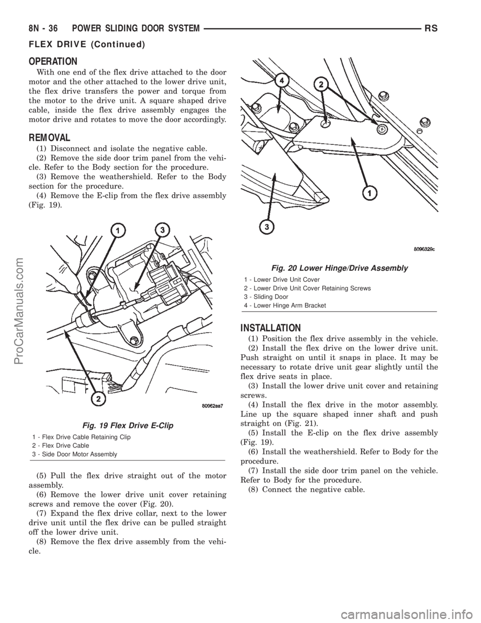
(Fig. 19).
(5) Pull the flex drive straight out of the motor
assembly.
(6) Remove the lower drive unit cover retaining
screws and remove the cover (Fig. 20).
(7) Expand the flex drive collar, next to the lower
drive unit until the flex drive can be pulled straight
off the lower drive unit.
(8) Remove the flex drive assembly from the vehi-
cle.
INSTALLATION
(1) Position the flex drive assembly in the vehicle.
(2) Install the flex drive on the lower drive unit.
Push straight on until it snaps in place. It may be
necessary to rotate drive unit gear slightly until the
flex drive seats in place.
(3) Install the lower drive unit cover and retaining
screws.
(4) Install the flex drive in the motor assembly.
Line up the square shaped inner shaft and push
straight on (Fig. 21).
(5) Install the E-clip on the flex drive assembly
(Fig. 19).
(6) Install the weathershield. Refer to Body for the
procedure.
(7) Install the side door trim panel on the vehicle.
Refer to Body for the procedure.
(8) Connect the negative cable.
Fig. 19 Flex Drive E-Clip
1 - Flex Drive Cable Retaining Clip
2 - Flex Drive Cable
3 - Side Door Motor Assembly
Fig. 20 Lower Hinge/Drive Assembly
1 - Lower Drive Unit Cover
2 - Lower Drive Unit Cover Retaining Screws
3 - Sliding Door
4 - Lower Hinge Arm Bracket
8N - 36 POWER SLIDING DOOR SYSTEMRS
FLEX DRIVE (Continued)
ProCarManuals.com
Page 587 of 2399

POWER MIRRORS
TABLE OF CONTENTS
page page
POWER MIRRORS
DESCRIPTION.........................46
OPERATION...........................46
DIAGNOSIS AND TESTING - POWER
MIRRORS...........................46
AUTOMATIC DAY / NIGHT MIRROR
DESCRIPTION.........................47
OPERATION...........................47
DIAGNOSIS AND TESTING - AUTOMATIC DAY
/ NIGHT MIRROR......................48
REMOTE SWITCH
DIAGNOSIS AND TESTING - REMOTE
SWITCH............................49REMOVAL.............................49
INSTALLATION.........................49
SIDEVIEW MIRROR
REMOVAL.............................49
POWER FOLDAWAY MIRROR SWITCH -
EXPORT
DESCRIPTION.........................49
OPERATION...........................50
REMOVAL.............................50
INSTALLATION.........................50
POWER MIRRORS
DESCRIPTION
If equipped with power mirrors, the control switch
is located on the instrument panel to the left of the
headlamp switch.
OPERATION
The power mirrors are connected to battery feed at
all times. Each mirror head contains two electric
motors, two drive mechanisms, an electric heating
element, and the mirror glass. If the vehicle is
equipped with the optional memory system, each
mirror head also contains both a horizontal and a
vertical motor position sensor. One motor and drive
controls mirror up-and-down movement, and the
other controls right-and-left movement.
An optional driver side outside electrochromic mir-
ror is able to automatically change its reflectance
level. This mirror is controlled by the circuitry of the
automatic day/night inside rear view mirror. A thin
layer of electrochromic material between two pieces
of conductive glass make up the face of the mirror.Two photocell sensors on the inside rear view mirror
are used to monitor light levels and adjust the reflec-
tance of both the inside and driver side outside mir-
rors. This change in reflectance helps to reduce the
glare of headlamps approaching the vehicle from the
rear. (Refer to 8 - ELECTRICAL/POWER MIRRORS/
AUTOMATIC DAY / NIGHT MIRROR - DESCRIP-
TION) for more information on this system.
The motors which operate the mirrors are part of
the mirror assembly and cannot be serviced sepa-
rately.
DIAGNOSIS AND TESTING - POWER MIRRORS
(1) Remove Power Mirror Switch. (Refer to 8 -
ELECTRICAL/POWER MIRRORS/POWER MIRROR
SWITCH - REMOVAL).
(2) Disconnect wiring harness connector to the
power mirror switch and headlamp switch.
(3) Using two jumper wires:
²Connect one to a 12-volt source
²Connect the other to a good body ground
²Refer to the Mirror Test Chart for wire hookups
at the switch connector (Fig. 1).
8N - 46 POWER MIRRORSRS
ProCarManuals.com
Page 588 of 2399

POWER MIRROR MOTOR TEST
SWITCH CONNECTOR
12 Volts Ground MIRROR REACTION
Right Left
PIN 12 PIN 6 Ð UP
PIN 7 PIN 6 Ð LEFT
PIN 6 PIN 12 Ð DOWN
PIN 6 PIN 7 Ð RIGHT
PIN 13 PIN 1 UP Ð
PIN 8 PIN 1 LEFT Ð
PIN 1 PIN 13 DOWN Ð
PIN 1 PIN 8 RIGHT Ð
PIN 5 PIN 11 LAMP LAMP
(4) If results shown in table are not obtained,
check for broken or shorted circuit, or replace mirror
assembly as necessary.
AUTOMATIC DAY / NIGHT
MIRROR
DESCRIPTION
An automatic dimming inside day/night rear view
mirror and an automatic dimming driver side outside
rear view mirror are available factory-installed
options on this model. Following is a general descrip-
tion of this optional equipment.
The automatic day/night mirror is able to automat-
ically change its reflectance. A thin layer of electro-
chromic material between two pieces of conductiveglass make up the face of the mirror. Two photocell
sensors are used to monitor light levels and adjust
the reflectance of the mirror to reduce the glare of
headlamps approaching the vehicle from the rear.
For removal procedures, (Refer to 23 - BODY/IN-
TERIOR/REAR VIEW MIRROR - REMOVAL).
OPERATION
The ambient photocell sensor faces forward, to
detect the outside light levels. A second sensor faces
rearward to detect the light level received through
the vehicles back window. When the difference
between the two light levels becomes too great (the
light level received at the rear of the mirror is much
higher than that at the front of the mirror), the mir-
ror begins to darken.
Fig. 1 Power Mirror Connector
RSPOWER MIRRORS8N-47
POWER MIRRORS (Continued)
ProCarManuals.com
Page 589 of 2399
The mirror switch allows the driver a manual con-
trol of whether the automatic dimming feature is
operational. When AUTO is selected a small Light-
Emitting Diode (LED), to the right of the mirror
switch, is illuminated. The automatic dimming fea-
ture will only operate when the ignition switch is in
the On position. The mirror also senses the backup
lamp circuit, and will automatically disable its self-
dimming feature whenever the transmission gear
selector is in the Reverse position.
NOTE: The mirror always defaults to an ON state
upon ignition.
The driver side automatic dimming mirror is stan-
dard with the automatic dimming inside mirror. The
signal to control the dimming of that mirror is gen-
erated by the automatic day/night inside rear view
mirror circuitry. That signal is then delivered to the
driver side outside rear view mirror on a hard wired
circuit.
The automatic day/night mirror cannot be
repaired. If faulty or damaged, the entire inside rear
view mirror assembly must be replaced.
DIAGNOSIS AND TESTING - AUTOMATIC DAY /
NIGHT MIRROR
For circuit descriptions and diagrams, refer to the
appropriate wiring information. The wiring informa-
tion includes wiring diagrams, proper wire and con-
nector repair procedures, details of wire harness
routing and retention, connector pin-out information
and location views for the various wire harness con-
nectors, splices and grounds.
(1) Check the fuse in the intelligent power module.
If OK, go to Step 2. If not OK, repair the shorted cir-
cuit or component as required and replace the faulty
fuse.
(2) Turn the ignition switch to the On position.
Check for battery voltage at the fuse in the intelli-
gent power module. If OK, go to Step 3. If not OK,
repair the open circuit to the ignition switch as
required.
(3) Unplug the wire harness connector from the
automatic day/night mirror. Check for battery voltage
at the fused ignition switch output circuit cavity of
the automatic day/night mirror wire harness connec-
tor. If OK, go to Step 4. If not OK, repair the open
circuit to the junction block as required.
(4) Turn the ignition switch to the Off position.
Check for continuity between the ground circuit cav-
ity of the automatic day/night mirror wire harness
connector and a good ground. There should be conti-
nuity. If OK, go to Step 5. If not OK, repair the cir-
cuit to ground as required.(5) Turn the ignition switch to the On position. Set
the parking brake. Place the transmission gear selec-
tor lever in the Reverse position. Check for battery
voltage at the backup lamp switch output circuit cav-
ity of the automatic day/night mirror wire harness
connector. If voltage is present, reinstall the auto-
matic day/night mirror wire harness connector and
go to Step 6. If not OK, repair the open circuit as
required.
(6) Place the transmission gear selector lever in
the Neutral position. Place the automatic day/night
mirror switch in the On (LED in the switch is
lighted) position. Cover the forward facing ambient
photocell sensor to keep out any ambient light.
NOTE: The ambient photocell sensor must be cov-
ered completely, so that no light reaches the sen-
sor. Use a finger pressed tightly against the sensor,
or cover the sensor completely with electrical tape.
(7) Shine a light into the rearward facing head-
lamp photocell sensor. The automatic day/night mir-
ror should darken. The automatic day/night mirror
should darken within 2 minutes if testing for the
first time. For immediate response, turn the vehicle
OFF and back ON with the forward-facing light sen-
sor still covered. This defeats the day-detect logic. If
OK, go to Step 8. If not OK, replace the faulty mirror
unit.
(8) With the mirror darkened, place the transmis-
sion gear selector lever in the Reverse position. The
automatic day/night mirror should return to its nor-
mal reflectance. If not OK, replace the faulty mirror
unit.
Bench testing both mirrors can be done, of care is
exercised. For an inside mirror, the pin closest to he
mount is 12V (+), the next is 12V (-). The third is
reverse override. The fourth is outside mirror (+),
and the fifth is outside mirror (-).Do not apply 12
volts to the fourth and fifth pins.With 12 volts
on pins 1 and 2, the mirror can be tested by blocking
the rear sensor and shining a light into the forward
sensor. For an outside mirror, there is a 2±pin con-
nector. Applying 1.2 volts will cause the mirror to
dim. If the mirror does not dim, the entire glass
assembly can be replaced just as it is when the glass
is broken.
WARNING: Do not apply 12 volts to the outside mir-
ror. Damage to the mirror will result.
8N - 48 POWER MIRRORSRS
AUTOMATIC DAY / NIGHT MIRROR (Continued)
ProCarManuals.com
Page 597 of 2399

(3) Remove the screws that secure the outboard
seat cushion side shield to the seat cushion frame.
Refer to the Body section of the service manual for
the procedure.
(4) Pull the outboard seat cushion side shield away
from the seat cushion frame far enough to access the
power seat switch wire harness connector.
(5) Disconnect the power seat wire harness connec-
tor from the power seat switch connector receptacle.
(6) Remove the screws that secure the power seat
switch to the inside of the outboard seat cushion side
shield.
(7) Remove the power seat switch from the out-
board seat cushion side shield.
INSTALLATION
(1) Position the power seat switch onto the out-
board seat cushion side shield.
(2) Install and tighten the screws that secure the
power seat switch to the inside of the outboard seat
cushion side shield. Tighten the screws to 1.5 N´m
(14 in. lbs.).
(3) Reconnect the power seat wire harness connec-
tor to the power seat switch connector receptacle.
(4) Position the outboard seat cushion side shield
onto the seat cushion frame
(5) Install and tighten the screws that secure the
outboard seat cushion side shield to the seat cushion
frame. Tighten the screws to 1.5 N´m (14 in. lbs.).
(6) Install the switch knobs on the switch control
levers, if equipped.
(7) Reconnect the battery negative cable.
MEMORY SET SWITCH
DESCRIPTION
Vehicles equipped with the memory system have a
memory switch mounted to the driver side front door
trim panel (Fig. 5). This switch is used to set and
recall all of the memory system settings for up to two
drivers. The memory switch is a resistor multiplexed
unit that is hard wired to the Body Control Module
(BCM). The BCM sends out the memory system set
and recall requests to the other electronic modules
over the Programmable Communications Interface
(PCI) data bus.
The memory switch cannot be adjusted or repaired
and, if faulty or damaged, it must be replaced. For
complete circuit diagrams, refer toWiring Dia-
grams.
OPERATION
The memory switch has three momentary switch
buttons labeled Set, 1 and 2. The Driver 1 and Driver
2 buttons are back-lit with Light-Emitting Diodes
(LED) for visibility. When the memory set switch is
depressed, a resistance value is sent to the Body
Control Module via hard wired connections. When
the memory system is in ªsetº mode a chime will be
generated by the body control module.
Fig. 4 Removing Switch Control Knobs - Typical
Fig. 5 Memory Switch Location
1 - Memory Switch
2 - Switch Bezel
8N - 56 POWER SEAT SYSTEMRS
DRIVER SEAT SWITCH (Continued)
ProCarManuals.com
Page 602 of 2399
cle. Check for battery voltage at the fused B(+)
circuit cavity of the power seat wire harness connec-
tor for the power seat switch. If OK, go to Step 4. If
not OK, repair the open fused B(+) circuit to the
power seat circuit breaker under the seat as
required.
(4) Check for continuity between the ground cir-
cuit cavity of the power seat wire harness connector
for the power seat switch and a good ground. There
should be continuity. If OK, go to Step 5. If not OK,
repair the open ground circuit to ground as required.
(5) Test the power seat switch. Refer toDiagnosis
and Testing Power Seat Switchin this section. If
the switch tests OK, test the circuits of the power
seat wire harness between the inoperative power seat
track adjuster motor and the power seat switch for
shorts or opens. If the circuits check OK, replace the
faulty power seat track unit. If the circuits are not
OK, repair the power seat wire harness as required.
REMOVAL
WARNING: SOME VEHICLES ARE EQUIPPED WITH
SEATBACK MOUNTED AIRBAGS. BEFORE
ATTEMPTING TO DIAGNOSE OR SERVICE ANY
SEAT OR POWER SEAT SYSTEM COMPONENT
YOU MUST FIRST DISCONNECT AND ISOLATE THE
BATTERY NEGATIVE CABLE. THEN WAIT TWO MIN-
UTES FOR THE SYSTEM CAPACITOR TO DIS-
CHARGE BEFORE FURTHER SYSTEM SERVICE.
THIS IS THE ONLY SURE WAY TO DISABLE THE
AIRBAG SYSTEM. FAILURE TO DO SO COULD
RESULT IN ACCIDENTAL AIRBAG DEPLOYMENT
AND POSSIBLE PERSONAL INJURY.
(1) Remove the appropriate seat from the vehicle
and place it on a clean work surface(Refer to 23 -
BODY/SEATS/SEAT - REMOVAL).
(2) Remove the Body Control Module retaining
screws.
(3) Disconnect the body control module electrical
connectors and remove the body control module from
the power seat track.
(4) Remove the rear fabric blocker trim panel from
the rear of the front seat.
(5) Remove the seat side cover and power seat
switch as an assembly (Refer to 23 - BODY/SEATS/
SEAT CUSHION SIDE COVERS - REMOVAL).
(6) Disconnect all electrical connectors connecting
the power seat track to the seat assembly.
(7) Pull the seat back trim cover up slightly to
access and remove the two seat back frame mounting
bolts and also remove two seat back recliner bolts.
(8) Remove four seat track mounting bolts from
the seat cushion pan.
(9) Remove the power seat track from the seat.
INSTALLATION
(1) Position the seat cushion on the seat track.
(2) Install the four seat track retaining bolts in the
seat cushion pan. Torque the bolts to 28.5 N´m.
(3) Position the seat back and install the two seat
back frame mounting bolts and the two seat back
recliner bolts. Torque the bolts to 55 N´m.
(4) Route and connect the electrical connectors
between the power seat track and the seat assembly.
(5) Install the seat side cover and power seat
switch as an assembly (Refer to 23 - BODY/SEATS/
SEAT CUSHION SIDE COVERS - INSTALLATION).
(6) Install the rear fabric blocker trim panel on the
rear of the front seat.
(7) Position the body control module and connect
the body control module electrical connectors.
(8) Install the Body Control Module retaining
screws.
(9) Install the seat assembly in the vehicle (Refer
to 23 - BODY/SEATS/SEAT - INSTALLATION).
PASSENGER POWER SEAT
TRACK
DESCRIPTION
The eight-way power seat option includes a electri-
cally operated power seat track unit located under
each front seat. The power seat circuit breaker is
mounted on the rear of the power seat track, just
behind the seat rear trim panel. The lower half of the
power seat track is secured to the floor panel via four
studs and nuts that must be accessed from the
underside of the vehicle. Four bolts secure the bot-
tom of the seat cushion frame to the upper half of the
power seat track unit. Four additional bolts secure
the seat back frame to the power seat track unit.
The power seat track unit includes four reversible
electric motors that are secured to the upper half of
the track unit. Each motor moves the seat adjuster
through a combination of worm-drive gearboxes and
screw-type drive units.
The front and rear of the seat are operated by two
separate vertical adjustment motors. These motors
can be operated independently of each other, tilting
the entire seat assembly forward or rearward; or,
they can be operated in unison by selecting the
proper power seat switch functions, which will raise
or lower the entire seat assembly. A third motor is
the horizontal adjustment motor, which moves the
seat track in the forward and rearward directions.
The forth motor is the recliner adjustment motor,
which moves the seat back in the forward and rear-
ward directions.
RSPOWER SEAT SYSTEM8N-61
DRIVER POWER SEAT TRACK (Continued)
ProCarManuals.com
Page 604 of 2399
(1) Remove the appropriate seat from the vehicle
(Refer to 23 - BODY/SEATS/SEAT - REMOVAL).
(2) Remove the rear fabric blocker trim panel from
the rear of the front seat.
(3) Remove the seat side cover and power seat
switch as an assembly (Refer to 23 - BODY/SEATS/
SEAT CUSHION SIDE COVERS - REMOVAL).
(4) Disconnect all electrical connectors connecting
the power seat track to the seat assembly.
(5) Pull the seat back trim cover up slightly to
access and remove the two seat back frame mounting
bolts and seat back recliner bolts.
(6) Remove four seat track mounting bolts from
the seat cushion pan.
(7) Remove the power seat track from the seat.INSTALLATION
(1) Position the seat cushion on the seat track.
(2) Install the four seat track retaining bolts in the
seat cushion pan. Torque the bolts to 28.5 N´m.
(3) Position the seat back and install the two seat
back frame mounting bolts and the two seat back
recliner bolts. Torque the bolts to 55 N´m.
(4) Route and connect the electrical connectors
between the power seat track and the seat assembly.
(5) Install the seat side cover and power seat
switch as an assembly (Refer to 23 - BODY/SEATS/
SEAT CUSHION - INSTALLATION).
(6) Install the rear fabric blocker trim panel on the
rear of the front seat.
(7) Install the seat assembly in the vehicle (Refer
to 23 - BODY/SEATS/SEAT - INSTALLATION).
RSPOWER SEAT SYSTEM8N-63
PASSENGER POWER SEAT TRACK (Continued)
ProCarManuals.com
Page 606 of 2399
If window moved completely up or down, reverse
the jumper probes and cycle window to the opposite
position to verify full operation.
If motor grunts and does not move, verify that reg-
ulator is not binding.
WIRING VOLTAGE TEST
The following wiring test determines whether or
not voltage is continuous through the body harness
to switch.
(1) Remove the power window switch and bezel
assembly from the driver door. (Refer to 8 - ELEC-
TRICAL/POWER WINDOWS/POWER WINDOW
SWITCH - REMOVAL).
(2) Disconnect wire connector from back of power
window switch.
(3) Switch ignition ON position.
(4) Connect the clip end of a 12 volt test light to
Pin 13 in door harness connector at the window
switch. Touch the test light probe to Pin 9 and then
to Pin 11.
²If the test light illuminates, the wiring circuit
between the battery and switch is OK.
²If the lamp does not illuminate, first check the
25 amp circuit breaker attached to the electrical dis-
tribution wiring bracket. If the circuit breaker is OK,
then check the 40 amp fuse (#28) in the Integrated
Power Module (IPM). If both components are OK,
then check for a broken wire.
²Refer to the appropriate wiring information.
The wiring information includes wiring diagrams,
proper wire and connector repair procedures, details
of wire harness routing and retention, connector pin-
out information and location views for the various
wire harness connectors, splices and grounds.
VENT WINDOW MOTOR
DIAGNOSIS AND TESTING - VENT WINDOW
MOTOR
If the power vent window motor is receiving proper
current and ground and does not operate proceed
with motor test. Refer to the appropriate wiring
information. The wiring information includes wiring
diagrams, proper wire and connector repair proce-
dures, details of wire harness routing and retention,
connector pin-out information and location views for
the various wire harness connectors, splices and
grounds.
(1) Remove D-pillar trim panel necessary to gain
access to power vent window motor wire connector,
(Refer to 23 - BODY/INTERIOR/LEFT D-PILLAR
TRIM PANEL - REMOVAL) or (Refer to 23 - BODY/
INTERIOR/RIGHT D-PILLAR TRIM PANEL -
REMOVAL).(2) Disconnect power vent window motor wire con-
nector from body harness.
(3) Using two jumper wires, connect one to a bat-
tery (+) source and the other to a good ground (-).
(4) Connect the Negative (-) jumper probe to one of
the motor connector terminals.
(5) Momentarily touch the Positive (+) jumper
probe to the other motor connector terminal.
When positive probe is connected the motor should
rotate in one direction to either move window open or
closed. If window is all the way open or closed the
motor will grunt and the crank system will flex when
actuated in that one direction.
Reverse jumper probes at the motor connector ter-
minals and window should now move in opposite
direction. If window does not move or grunt, replace
the motor.
If window moved completely open or closed, reverse
the jumper probes and cycle window to the opposite
position to verify full operation.
If motor grunts and does not move, verify that
crank system is not binding.
REMOVAL
(1) Disconnect and isolate the battery negative
cable.
(2) Remove D-pillar trim panel. (Refer to 23 -
BODY/INTERIOR/LEFT D-PILLAR TRIM PANEL -
REMOVAL) or (Refer to 23 - BODY/INTERIOR/
RIGHT D-PILLAR TRIM PANEL - REMOVAL).
(3) Disconnect wire connector from power vent
motor.
(4) Using a flat bladed tool, carefully lift the circu-
lar actuator link tab. Remove link from window ball
socket.
(5) Remove bolts holding power vent motor to
D-pillar (Fig. 1).
(6) Remove power vent motor.
INSTALLATION
(1) Obtain new vent window motor.
(2) Snap the actuator link socket onto the quarter
window ball socket. Using a soft rubber mallet, push
the circular link tab flush with link surface.
(3) Install bolts holding power vent motor to D-pil-
lar.
(4) Reconnect wire connector to power vent motor.
(5) Reconnect the battery negative cable.
(6) Cycle quarter window open/close to verify func-
tion.
(7) Install D-pillar trim panel.
RSPOWER WINDOWS8N-65
POWER WINDOWS (Continued)
ProCarManuals.com