light CHRYSLER CARAVAN 2002 Service Manual
[x] Cancel search | Manufacturer: CHRYSLER, Model Year: 2002, Model line: CARAVAN, Model: CHRYSLER CARAVAN 2002Pages: 2399, PDF Size: 57.96 MB
Page 1033 of 2399

Component Page
C322 (Memory)..................... 8W-80-39
C322 (Memory)..................... 8W-80-39
C324 (Manual Sliding Door)........... 8W-80-39
C324 (Manual Sliding Door)........... 8W-80-40
C325 (Manual Sliding Door)........... 8W-80-40
C325 (Manual Sliding Door)........... 8W-80-40
C326............................. 8W-80-40
C326............................. 8W-80-40
C327............................. 8W-80-40
C327............................. 8W-80-41
C329 (Diesel)....................... 8W-80-41
C329 (Diesel)....................... 8W-80-41
C330 (Diesel)....................... 8W-80-41
C330 (Diesel)....................... 8W-80-41
C331 (Diesel)....................... 8W-80-42
C331 (Diesel)....................... 8W-80-42
C332 (ATC)........................ 8W-80-42
C332 (ATC)........................ 8W-80-42
Cabin Heater Assist C1 (Diesel)........ 8W-80-42
Cabin Heater Assist C2 (Diesel)........ 8W-80-43
Camshaft Position Sensor (Diesel)...... 8W-80-43
Camshaft Position Sensor (Gas)........ 8W-80-43
CD Changer....................... 8W-80-43
Center Dome Lamp (Base/High Line).... 8W-80-43
Center High Mounted Stop Lamp....... 8W-80-44
Clockspring C1..................... 8W-80-44
Clockspring C2..................... 8W-80-44
Clockspring C3..................... 8W-80-44
Clockspring C4..................... 8W-80-44
Clockspring C5..................... 8W-80-45
Clutch Pedal Interlock Switch (MTX).... 8W-80-45
Clutch Pedal Interlock Switch Jumper
(ATX) .......................... 8W-80-45
Clutch Pedal Upstop Switch (Diesel)..... 8W-80-45
Controller Antilock Brake............. 8W-80-46
Crank Case Ventilation Heater (Diesel) . . 8W-80-46
Crankshaft Position Sensor (Diesel)..... 8W-80-46
Crankshaft Position Sensor (Gas)....... 8W-80-47
Data Link Connector................. 8W-80-47
Diagnostic Junction Port.............. 8W-80-47
Dosing Pump (Diesel)................ 8W-80-48
Driver Airbag C1.................... 8W-80-48
Driver Airbag C2.................... 8W-80-48
Driver Blend Door Actuator (ATC)...... 8W-80-48
Driver Blend Door Actuator (MTC)...... 8W-80-48
Driver Door Courtesy Lamp........... 8W-80-49
Driver Door Lock Switch.............. 8W-80-49
Driver Heated Seat Back............. 8W-80-49
Driver Heated Seat Cushion........... 8W-80-49
Driver Heated Seat Module C1......... 8W-80-49
Driver Heated Seat Module C2......... 8W-80-50
Driver Heated Seat Module C3......... 8W-80-50
Driver Power Seat Front Riser Motor.... 8W-80-50Component Page
Driver Power Seat Front Riser
Position Sensor................... 8W-80-50
Driver Power Seat Horizontal Motor..... 8W-80-50
Driver Power Seat Horizontal
Position Sensor................... 8W-80-51
Driver Power Seat Rear Riser Motor.... 8W-80-51
Driver Power Seat Rear Riser
Position Sensor................... 8W-80-51
Driver Power Seat Recliner Motor...... 8W-80-51
Driver Power Seat Recliner
Position Sensor................... 8W-80-51
Driver Power Seat Switch............. 8W-80-52
Driver Power Window Motor........... 8W-80-52
Driver Power Window Switch
(Except Lowline).................. 8W-80-52
Driver Power Window Switch (Lowline) . . 8W-80-53
Driver Power Window Switch (RHD).... 8W-80-53
Driver Seat Belt Switch.............. 8W-80-53
Driver Seat Belt Tensioner............ 8W-80-53
EGR Solenoid (Diesel)................ 8W-80-54
EGR Solenoid (Gas)................. 8W-80-54
Electric Wiper De-Icer C1............. 8W-80-54
Electric Wiper De-Icer C2............. 8W-80-54
Engine Control Module C1 (Diesel)...... 8W-80-55
Engine Control Module C2 (Diesel)...... 8W-80-57
Engine Coolant Temp Sensor (Diesel).... 8W-80-57
Engine Coolant Temp Sensor (Gas)...... 8W-80-58
Engine Oil Pressure Sensor (Diesel)..... 8W-80-58
Engine Oil Pressure Switch (Gas)....... 8W-80-58
Engine Oil Temperature Sensor (Diesel) . . 8W-80-58
EVAP/Purge Solenoid (Gas)............ 8W-80-58
Evaporator Temperature Sensor........ 8W-80-59
Floor Console Lamp................. 8W-80-59
Floor Console Power Outlet........... 8W-80-59
Front Blower Module C1 (ATC)......... 8W-80-59
Front Blower Module C2 (ATC)......... 8W-80-59
Front Cigar Lighter................. 8W-80-60
Front Reading Lamps/Switch.......... 8W-80-60
Front Washer Pump Motor............ 8W-80-60
Fuel Heater (Diesel)................. 8W-80-60
Fuel Injector No. 1 (2.4L/3.3L/3.8L)..... 8W-80-60
Fuel Injector No. 1 (Diesel)............ 8W-80-61
Fuel Injector No. 2 (2.4L/3.3L/3.8L)..... 8W-80-61
Fuel Injector No. 2 (Diesel)............ 8W-80-61
Fuel Injector No. 3 (2.4L/3.3L/3.8L)..... 8W-80-61
Fuel Injector No. 3 (Diesel)............ 8W-80-61
Fuel Injector No. 4 (2.4L/3.3L/3.8L)..... 8W-80-62
Fuel Injector No. 4 (Diesel)............ 8W-80-62
Fuel Injector No. 5 (3.3L/3.8L)......... 8W-80-62
Fuel Injector No. 6 (3.3L/3.8L)......... 8W-80-62
Fuel Pressure Sensor (Diesel).......... 8W-80-62
Fuel Pressure Solenoid (Diesel)......... 8W-80-63
Fuel Pump Module.................. 8W-80-63
Generator......................... 8W-80-63
8W - 80 - 2 8W-80 CONNECTOR PIN-OUTSRS
ProCarManuals.com
Page 1049 of 2399

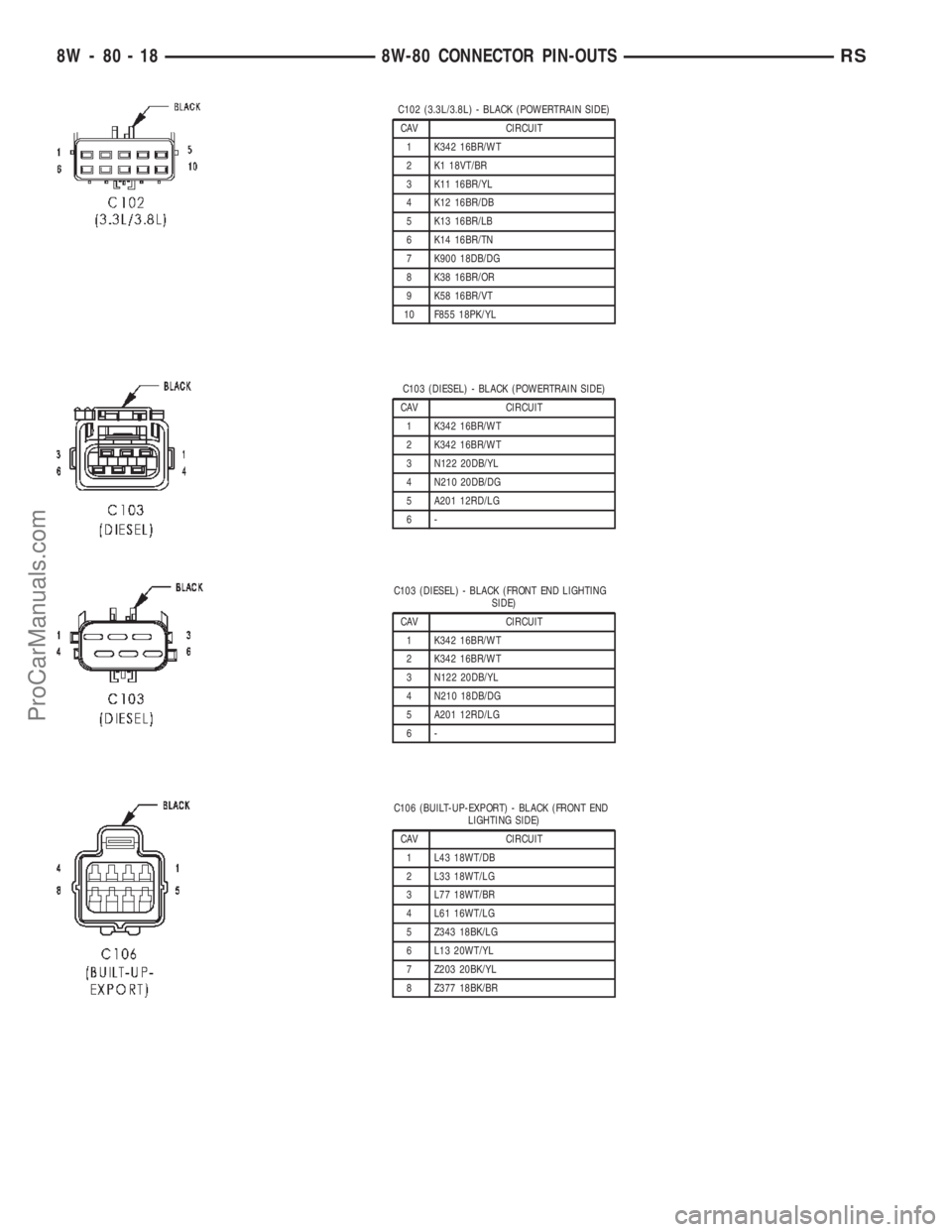
C102 (3.3L/3.8L) - BLACK (POWERTRAIN SIDE)
CAV CIRCUIT
1 K342 16BR/WT
2 K1 18VT/BR
3 K11 16BR/YL
4 K12 16BR/DB
5 K13 16BR/LB
6 K14 16BR/TN
7 K900 18DB/DG
8 K38 16BR/OR
9 K58 16BR/VT
10 F855 18PK/YL
C103 (DIESEL) - BLACK (POWERTRAIN SIDE)
CAV CIRCUIT
1 K342 16BR/WT
2 K342 16BR/WT
3 N122 20DB/YL
4 N210 20DB/DG
5 A201 12RD/LG
6-
C103 (DIESEL) - BLACK (FRONT END LIGHTING
SIDE)
CAV CIRCUIT
1 K342 16BR/WT
2 K342 16BR/WT
3 N122 20DB/YL
4 N210 18DB/DG
5 A201 12RD/LG
6-
C106 (BUILT-UP-EXPORT) - BLACK (FRONT END
LIGHTING SIDE)
CAV CIRCUIT
1 L43 18WT/DB
2 L33 18WT/LG
3 L77 18WT/BR
4 L61 16WT/LG
5 Z343 18BK/LG
6 L13 20WT/YL
7 Z203 20BK/YL
8 Z377 18BK/BR
8W - 80 - 18 8W-80 CONNECTOR PIN-OUTSRS
ProCarManuals.com
Page 1050 of 2399

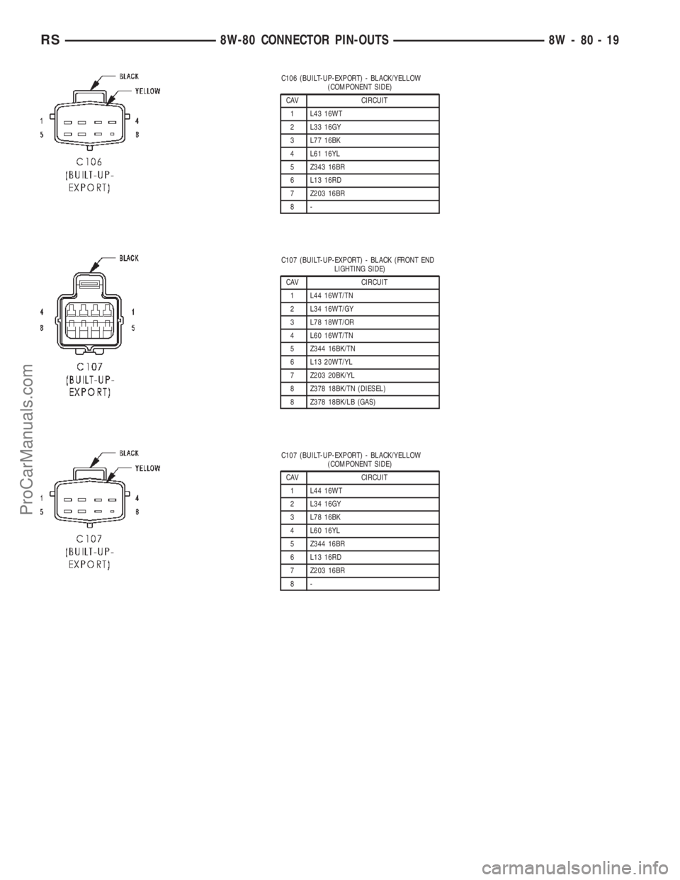
C106 (BUILT-UP-EXPORT) - BLACK/YELLOW
(COMPONENT SIDE)
CAV CIRCUIT
1 L43 16WT
2 L33 16GY
3 L77 16BK
4 L61 16YL
5 Z343 16BR
6 L13 16RD
7 Z203 16BR
8-
C107 (BUILT-UP-EXPORT) - BLACK (FRONT END
LIGHTING SIDE)
CAV CIRCUIT
1 L44 16WT/TN
2 L34 16WT/GY
3 L78 18WT/OR
4 L60 16WT/TN
5 Z344 16BK/TN
6 L13 20WT/YL
7 Z203 20BK/YL
8 Z378 18BK/TN (DIESEL)
8 Z378 18BK/LB (GAS)
C107 (BUILT-UP-EXPORT) - BLACK/YELLOW
(COMPONENT SIDE)
CAV CIRCUIT
1 L44 16WT
2 L34 16GY
3 L78 16BK
4 L60 16YL
5 Z344 16BR
6 L13 16RD
7 Z203 16BR
8-
RS8W-80 CONNECTOR PIN-OUTS8W-80-19
ProCarManuals.com
Page 1091 of 2399

FRONT CIGAR LIGHTER - RED/NATURAL 3 WAY
CAV CIRCUIT FUNCTION
1 F306 16DB/PK FUSED ACCESSORY RELAY OUTPUT
1 F306 16DB/PK FUSED ACCESSORY RELAY OUTPUT
2 E14 20OR/TN (BUILT-UP-EXPORT) PANEL LAMPS DRIVER
3 Z736 16BK/YL GROUND
FRONT READING LAMPS/SWITCH - BLACK 6 WAY
CAV CIRCUIT FUNCTION
1 E15 20OR/DB (EXCEPT BASE) ASH/RECEIVER LAMP FEED
2 Z137 20BK/LB GROUND
3- -
4 M27 20YL/LB READING LAMPS DRIVER
5 M24 20YL/WT COURTESY LAMPS DRIVER
6- -
FRONT WASHER PUMP MOTOR - BLACK 2 WAY
CAV CIRCUIT FUNCTION
1 W10 18BR FRONT WASHER PUMP MOTOR CONTROL
2 F300 18OR/PK FUSED ACCESSORY RELAY OUTPUT
FUEL HEATER (DIESEL) - BLACK 2 WAY
CAV CIRCUIT FUNCTION
1 N1 16RD FUEL HEATER RELAY OUTPUT
2 Z201 18RD GROUND
FUEL INJECTOR NO. 1 (2.4L/3.3L/3.8L) - BLACK 2 WAY
CAV CIRCUIT FUNCTION
1 K342 16BR/WT AUTOMATIC SHUT DOWN RELAY OUTPUT
2 K11 16BR/YL FUEL INJECTOR NO. 1 DRIVER
8W - 80 - 60 8W-80 CONNECTOR PIN-OUTSRS
ProCarManuals.com
Page 1151 of 2399

CONNECTOR NAME/NUMBER COLOR LOCATION FIG.
Driver Power Seat Front Riser
MotorRD At Seat N/S
Driver Power Seat Horizontal Motor BK At Seat N/S
Driver Power Seat Rear Riser
MotorRD At Seat N/S
Driver Power Seat Recliner Motor GN At Seat N/S
Driver Power Seat Switch GN At Switch N/S
Driver Power Window Motor RD At Motor N/S
Driver Power Window Switch GN At Switch N/S
Driver Power Window Switch
(RHD)NAT At Switch N/S
Driver Seatbelt Switch WT At Switch on Seat Harness N/S
Driver Seatbelt Tensioner On Seat Harness N/S
EGR Solenoid (Diesel) BK Above Transmission
Right Side of EngineN/S
EGR Solenoid GY Above Transmission
Right Side of Engine9, 10, 11, 13
Electric Wiper De-Icer-C1 WT Right Side Instrument Panel 15, 1923
Electric Wiper De-Icer-C2 WT Left Side Instrument Panel 15, 16, 22
Engine Control Module C1 (Diesel) BK Right Side of Engine 11
Engine Control Module C2 (Diesel) BK Right Side of Engine 11
Engine Coolant Temperature
Sensor (Gas)BK On Cylinder Block N/S
Engine Coolant Temperature
Sensor (Diesel)BL On Cylinder Block 11
Engine Oil Pressure Sensor
(Diesel)BK Rear of Engine 12
Engine Oil Pressure Switch (Gas) LTGN On Cylinder Block 9
Engine Oil Temperature Sensor
(Diesel)BK Rear of Engine 12
EVAP/Purge Solenoid BK Right Motor Mount 9, 13
Evaporator Temperature Sensor BK Right Side of HVAC N/S
Floor Console Lamp BK At Lamp N/S
Floor Console Power Outlet RD At Front Console N/S
Front Blower Module C1 (ATC) BK On HVAC N/S
Front Blower Module C2 (ATC) BK On HVAC N/S
Front Cigar Lighter RD/NAT Rear of Lighter 15, 18, 20
Front Reading Lamps/Switch BK At Switch N/S
Front Washer Pump Motor BK Right Fender Well 3
Fuel Heater (Diesel) BK Left Rear Engine Compartment N/S
Fuel Injector No.1 BK At Fuel Injector N/S
Fuel Injector No.1 (Diesel) BK At Fuel Injector 11
Fuel Injector No.2 BK At Fuel Injector N/S
Fuel Injector No.2 (Diesel) BK At Fuel Injector 11
8W - 91 - 4 8W-91 CONNECTOR/GROUND/SPLICE LOCATIONRS
CONNECTOR/GROUND/SPLICE LOCATION (Continued)
ProCarManuals.com
Page 1160 of 2399

SPLICE NUMBER LOCATION FIG.
S177 In Right Headlamp Wiring Assembly N/S
S179 In Left Headlamp Wiring Assembly N/S
S187 (2.5L) Near T/O for Engine Control Module C1 11
S188 (2.5L) Near T/O for Radiator Fan Relay No.1 2
S201 In T/O to Instrument Panel Speaker 15, 21
S202 Near T/O for Instrument Panel Switch Bank 15, 21
S203 Near T/O for Instrument Panel Switch Bank 15, 21
S204 Near T/O to Instrument Panel Speaker 15, 21
S205 Near T/O for C201 15
S206 Near T/O for Instrument Cluster 15
S207 In A/C Unit Assembly N/S
S208 (RHD) Between T/O for Antenna Connector and T/O for Front
Cigar Lighter21
S209 (RHD) Between T/O for Front Cigar Lighter and T/O for Brake
Transmission Shift Interlock Solenoid21
S210 (RHD) Near T/O for C203 21
S211 In Steering Column Wiring Assembly N/S
S212 In Steering Column Wiring Assembly N/S
S302 In Floor Pan Track Wiring 31
S303 In T/O to Data Link Connector 31
S304 Near T/O for C307 32
S305 Near T/O for Memory Seat/Mirror Module - C2 N/S
S306 In Floor Pan Track Wiring 32
S307 Near T/O for Memory Power Seat Switch N/S
S308 In Floor Pan Track Wiring 31
S309 In Floor Pan Track Wiring 31
S310 Near T/O for C301 30
S311 In Floor Pan Track Wiring 29
S312 Near T/O for C320 N/S
S313 Near T/O for Power Liftgate Module 40
S314 In Floor Pan Track Wiring 29
S315 In Floor Pan Track Wiring 29
S316 In Floor Pan Track Wiring 29
S317 Near T/O for C101 30
S318 Near T/O for Power Seat Circuit Breaker N/S
S319 In Floor Pan Track Wiring 32
S320 Near T/O for C200 31
S321 In T/O to Data Link Connector 31
S322 Near T/O for C301 30
S323 In Floor Pan Track Wiring 31
S324 In Floor Pan Track Wiring 29
S325 In Floor Pan Track Wiring 29
S326 Near T/O for C101 30
RS8W-91 CONNECTOR/GROUND/SPLICE LOCATION8W-91-13
CONNECTOR/GROUND/SPLICE LOCATION (Continued)
ProCarManuals.com
Page 1200 of 2399

tion. The IOD fuse is a 15 ampere blade-type car-
tridge fuse and, when removed, it is stored in a fuse
cavity adjacent to the washer fuse within the IPM.
OPERATION
The term ignition-off draw identifies a normal con-
dition where power is being drained from the battery
with the ignition switch in the Off position. The IOD
fuse feeds the memory and sleep mode functions for
some of the electronic modules in the vehicle as well
as various other accessories that require battery cur-
rent when the ignition switch is in the Off position,
including the clock. The only reason the IOD fuse is
removed is to reduce the normal IOD of the vehicle
electrical system during new vehicle transportation
and pre-delivery storage to reduce battery depletion,
while still allowing vehicle operation so that the
vehicle can be loaded, unloaded and moved as needed
by both vehicle transportation company and dealer
personnel.
The IOD fuse is removed from the IPM fuse cavity
when the vehicle is shipped from the assembly plant.
Dealer personnel must install the IOD fuse when the
vehicle is being prepared for delivery in order to
restore full electrical system operation. Once the
vehicle is prepared for delivery, the IOD function of
this fuse becomes transparent and the fuse that has
been assigned the IOD designation becomes only
another Fused B(+) circuit fuse. The IOD fuse serves
no useful purpose to the dealer technician in the ser-
vice or diagnosis of any vehicle system or condition,
other than the same purpose as that of any other
standard circuit protection device.
The IOD fuse can be used by the vehicle owner as
a convenient means of reducing battery depletion
when a vehicle is to be stored for periods not to
exceed about thirty days. However, it must be
remembered that removing the IOD fuse will not
eliminate IOD, but only reduce this normal condition.
If a vehicle will be stored for more than about thirty
days, the battery negative cable should be discon-
nected to eliminate normal IOD; and, the battery
should be tested and recharged at regular intervals
during the vehicle storage period to prevent the bat-
tery from becoming discharged or damaged. Refer to
Battery Systemfor additional service information.
REMOVAL
(1) Turn the ignition switch to the Off position.
(2) Unlatch and open the cover of the intelligent
power module.
(3) Remove the IOD fuse from fuse location
markedIODof the Integrated Power Module (IPM).
(4) Store the removed IOD fuse by installing it in
the unused fuse storage markedSPAREof the IPM.
(5) Close and latch the IPM.
INSTALLATION
(1) Be certain the ignition switch is in the Off posi-
tion.
(2) Unlatch and open the cover of the Integrated
Power Module (IPM).
(3) Remove the stored 15 amp IOD fuse from fuse
storage markedSPAREof the IPM.
(4) Use a thumb to press the IOD fuse firmly down
into IPM fuse cavity markedIOD.
(5) Close and latch the IPM cover.
POWER OUTLET
DESCRIPTION
Accessory power outlets are standard equipment on
this model. Two power outlets are installed in the
instrument panel center lower bezel, which is located
near the bottom of the instrument panel center stack
area. Two additional power outlets are also incorpo-
rated into the vehicle, one on the left rear C-pillar
trim and the other in the center console, if equipped.
The power outlets bases are secured by a snap fit in
the appropriate bezels. A hinged plug flips closed to
conceal and protect the power outlet base when the
power outlet is not being used.
The power outlet receptacle unit and the power
outlet plugs are each available for service replace-
ment.
OPERATION
The power outlet base or receptacle shell is con-
nected to ground, and an insulated contact in the
bottom of the shell is connected to battery current.
The power outlet on the instrument panel marked
with a battery receives battery voltage from a fuse in
the Integrated Power Module (IPM) at all times. The
other power outlet on the instrument panel marked
with a key receives battery voltage only when the
key is in the on position.
The power outlet located in the center console
receives battery voltage all the time when positioned
between thefront seatsand key-on voltage when
positioned between therear seats. The power outlet
located on the C-pillar receives battery voltage only
when the key is in the on position.
DIAGNOSIS AND TESTING
DIAGNOSIS & TESTING - POWER OUTLET
For complete circuit diagrams, refer toCigar
Lighter/Power Outletin Wiring Diagrams.
RS8W-97 POWER DISTRIBUTION SYSTEM8W-97-5
IOD FUSE (Continued)
ProCarManuals.com
Page 1201 of 2399

WARNING: ON VEHICLES EQUIPPED WITH AIR-
BAGS, REFER TO RESTRAINTS BEFORE ATTEMPT-
ING ANY STEERING WHEEL, STEERING COLUMN,
SEAT OR INSTRUMENT PANEL COMPONENT DIAG-
NOSIS OR SERVICE. FAILURE TO TAKE THE
PROPER PRECAUTIONS COULD RESULT IN ACCI-
DENTAL AIRBAG DEPLOYMENT AND POSSIBLE
PERSONAL INJURY.
(1) Check the fused B(+) fuse in the Integrated
Power Module (IPM). If OK, go to Step 2. If not OK,
repair the shorted circuit or component as required
and replace the faulty fuse.
(2) Check for battery voltage at the fused B(+) fuse
in the IPM. If OK, go to Step 3. If not OK, repair the
open fused B(+) circuit to the IPM fuse as required.
(3)
Open the power outlet door. Check for continuity
between the inside circumference of the power outlet
receptacle and a good ground. There should be continu-
ity. If OK, go to Step 4. If not OK, go to Step 5.
(4) Check for battery voltage at the insulated con-
tact located at the back of the power outlet recepta-
cle. If not OK, go to Step 5.
(5) Disconnect and isolate the battery negative
cable. Remove the appropriate bezel. Check for conti-
nuity between the ground circuit cavity of the power
outlet wire harness connector and a good ground.
There should be continuity. If OK, go to Step 6. If not
OK, repair the open ground circuit to ground as
required.
(6) Connect the battery negative cable. Check for
battery voltage at the fused B(+) circuit cavity of the
power outlet wire harness connector. If OK, replace
the faulty power outlet receptacle. If not OK, repair
the open fused B(+) circuit to the IPM fuse as
required.
REMOVAL
(1) Disconnect and isolate the battery negative
cable.
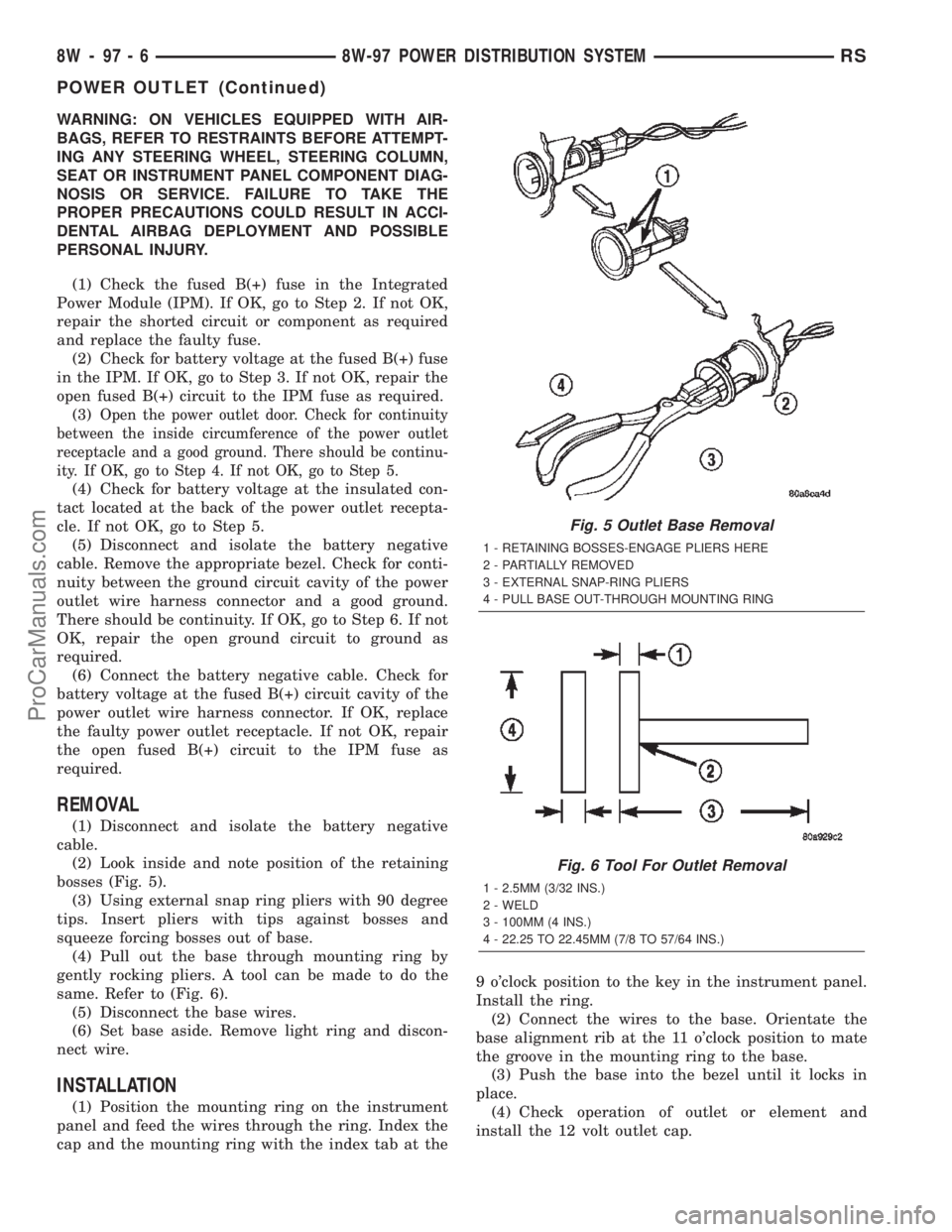
(2) Look inside and note position of the retaining
bosses (Fig. 5).
(3) Using external snap ring pliers with 90 degree
tips. Insert pliers with tips against bosses and
squeeze forcing bosses out of base.
(4) Pull out the base through mounting ring by
gently rocking pliers. A tool can be made to do the
same. Refer to (Fig. 6).
(5) Disconnect the base wires.
(6) Set base aside. Remove light ring and discon-
nect wire.
INSTALLATION
(1) Position the mounting ring on the instrument
panel and feed the wires through the ring. Index the
cap and the mounting ring with the index tab at the9 o'clock position to the key in the instrument panel.
Install the ring.
(2) Connect the wires to the base. Orientate the
base alignment rib at the 11 o'clock position to mate
the groove in the mounting ring to the base.
(3) Push the base into the bezel until it locks in
place.
(4) Check operation of outlet or element and
install the 12 volt outlet cap.
Fig. 5 Outlet Base Removal
1 - RETAINING BOSSES-ENGAGE PLIERS HERE
2 - PARTIALLY REMOVED
3 - EXTERNAL SNAP-RING PLIERS
4 - PULL BASE OUT-THROUGH MOUNTING RING
Fig. 6 Tool For Outlet Removal
1 - 2.5MM (3/32 INS.)
2 - WELD
3 - 100MM (4 INS.)
4 - 22.25 TO 22.45MM (7/8 TO 57/64 INS.)
8W - 97 - 6 8W-97 POWER DISTRIBUTION SYSTEMRS
POWER OUTLET (Continued)
ProCarManuals.com
Page 1205 of 2399

DIAGNOSIS AND TESTING - ENGINE
DIAGNOSIS - PERFORMANCE
CONDITION POSSIBLE CAUSE CORRECTION
ENGINE WILL NOT START 1. Weak battery. 1. Test battery. Charge or replace
as necessary. (Refer to 8 -
ELECTRICAL/BATTERY SYSTEM -
DIAGNOSIS AND TESTING)
2. Corroded or loose battery
connections.2. Clean and tighten battery
connections. Apply a coat of light
mineral grease to terminals.
3. Faulty starter. 3. Test starting system. (Refer to 8 -
ELECTRICAL/STARTING -
DIAGNOSIS AND TESTING)
4. Faulty coil(s) or control unit. 4. Test and replace as needed.
(Refer to Appropriate Diagnostic
Information)
5. Incorrect spark plug gap. 5. Set gap. (Refer to 8 -
ELECTRICAL/IGNITION CONTROL
- SPECIFICATIONS)
6. Contamination in fuel system. 6. Clean system and replace fuel
filter.
7. Faulty fuel pump. 7. Test fuel pump and replace as
needed. (Refer to Appropriate
Diagnostic Information)
8. Incorrect engine timing. 8. Check for a skipped timing
belt/chain.
ENGINE STALLS OR IDLES
ROUGH1. Idle speed too low. 1. Test minimum air flow. (Refer to
Appropriate Diagnostic Information)
2. Incorrect fuel mixture. 2. (Refer to Appropriate Diagnostic
Information)
3. Intake manifold leakage. 3. Inspect intake manifold, manifold
gasket, and vacuum hoses.
4. Faulty ignition coil(s). 4. Test and replace as necessary.
(Refer to Appropriate Diagnostic
Information)
9 - 4 ENGINE 2.4LRS
ENGINE 2.4L (Continued)
ProCarManuals.com
Page 1209 of 2399

CONDITION POSSIBLE CAUSES CORRECTION
OIL CONSUMPTION OR SPARK
PLUGS FOULED1. PCV system malfunction. 1. Check system and repair as
necessary. (Refer to 25 -
EMISSIONS CONTROL/
EVAPORATIVE EMISSIONS/PCV
VALVE - DIAGNOSIS AND
TESTING)
2. Worn, scuffed or broken rings. 2. Hone cylinder bores. Install new
rings.
3. Carbon in oil ring slots. 3. Install new rings.
4. Rings fitted too tightly in grooves. 4. Remove rings and check
grooves. If groove is not proper
width, replace piston.
5. Worn valve guide(s). 5. Replace cylinder head assembly.
6. Valve stem seal(s) worn or
damaged.6. Replace seal(s).
DIAGNOSIS AND TESTING - ENGINE OIL LEAK
INSPECTION
Begin with a thorough visual inspection of the
engine, particularly at the area of the suspected leak.
If an oil leak source is not readily identifiable, the
following steps should be followed:
(1) Do not clean or degrease the engine at this
time because some solvents may cause rubber to
swell, temporarily stopping the leak.
(2) Add an oil soluble dye (use as recommended by
manufacturer). Start the engine and let idle for
approximately 15 minutes. Check the oil dipstick to
make sure the dye is thoroughly mixed as indicated
with a bright yellow color under a black light.
(3) Using a black light, inspect the entire engine
for fluorescent dye, particularly at the suspected area
of oil leak. If the oil leak is found and identified,
repair as necessary.
(4) If dye is not observed, drive the vehicle at var-
ious speeds for approximately 24 km (15 miles), and
repeat inspection.
(5)If the oil leak source is not positively
identified at this time, proceed with the air leak
detection test method as follows:
²Disconnect the fresh air hose (make-up air) at
the cylinder head cover and plug or cap the nipple on
the cover.
²Remove the PCV valve hose from the cylinder
head cover. Cap or plug the PCV valve nipple on the
cover.
²Attach an air hose with pressure gauge and reg-
ulator to the dipstick tube.
CAUTION: Do not subject the engine assembly to
more than 20.6 kpa (3 PSI) of test pressure.²Gradually apply air pressure from 1 psi to 2.5
psi maximum while applying soapy water at the sus-
pected source. Adjust the regulator to the suitable
test pressure that provides the best bubbles which
will pinpoint the leak source. If the oil leak is
detected and identified, repair per service manual
procedures.
²If the leakage occurs at the crankshaft rear oil
seal area, refer to the section, Inspection for Rear
Seal Area Leak.
(6) If no leaks are detected, turn off the air supply.
Remove the air hose, all plugs, and caps. Install the
PCV valve and fresh air hose (make-up air). Proceed
to next step.
(7) Clean the oil off the suspect oil leak area using
a suitable solvent. Drive the vehicle at various
speeds approximately 24 km (15 miles). Inspect the
engine for signs of an oil leak by using a black light.
NOTE: If oil leakage is observed at the dipstick tube
to block location; remove the tube, clean and reseal
using MoparTStud & Bearing Mount (press fit tube
applications only), and for O-ring style tubes,
remove tube and replace the O-ring seal.
INSPECTION FOR REAR SEAL AREA LEAKS
Since it is sometimes difficult to determine the
source of an oil leak in the rear seal area of the
engine, a more involved inspection is necessary. The
following steps should be followed to help pinpoint
the source of the leak.
If the leakage occurs at the crankshaft rear oil seal
area:
(1) Disconnect the battery.
(2) Raise the vehicle.
9 - 8 ENGINE 2.4LRS
ENGINE 2.4L (Continued)
ProCarManuals.com