warning CHRYSLER CARAVAN 2002 Service Manual
[x] Cancel search | Manufacturer: CHRYSLER, Model Year: 2002, Model line: CARAVAN, Model: CHRYSLER CARAVAN 2002Pages: 2399, PDF Size: 57.96 MB
Page 625 of 2399

SIDE IMPACT AIRBAG
CONTROL MODULE
DESCRIPTION
The side airbag system is a safety devise designed
to reduce the risk of fatality or serious injury, caused
by a side impact of the vehicle.
Vehicles equipped with side impact airbags use two
Side Impact Airbag Control Modules (SIACM). One is
located on each respective side body B-pillar. Each
contains an impact sensor that senses a side impact
occurrence. The SIACM communicates with the ORC
via the PCI bus in order to notify the driver of any
potential side airbag system problem.
OPERATION
The impact sensor provides verification of the
direction and severity of the side impact. The right
side SIACM controls the right seat airbag. The left
side SIACM controls the left seat airbag. In the event
of a side impact the appropriate SIACM will send an
electronic signal to its airbag, deploying the airbag.
The SIACM communicates with the Occupant
Restraint Controller (ORC) via the PCI bus circuit.
The accelerometer pulses are sent to a micropro-
cessor, which contains a decision algorithm. When an
impact is severe enough to require airbag protection,
the SIACM microprocessor sends a signal to deploy
the side airbag that completes the electrical circuits
to the right or left side airbag. The sensor is cali-
brated for the specific vehicle and reacts to the sever-
ity and direction of the impact.
REMOVAL
NOTE: Diagnose the SIACM using the service/diag-
nostic manual.
(1) Disconnect and isolate the battery negative
cable terminal.
(2) Remove the lower B-pillar trim from the appro-
priate side of the vehicle. Refer to Body, Interior,
B-Pillar Lower Trim, Removal.
(3) Remove the three SIACM retaining screws and
remove the module from the vehicle.
(4) Disconnect the SIACM electrical connector.
INSTALLATION
WARNING: DO NOT INSTALL THE SIACM IF THE
MOUNTING LOCATION IS DEFORMED OR DAM-
AGED.
(1) Connect the SIACM electrical connector.
(2) Place the module in the slot on their respective
B-pillar. Install the three SIACM retaining screws.
Torque screws to 5.7 - 7.9 N´m (50 - 70 lbs.)
CAUTION: Use the correct screws when installing
the SIACM.
(3) Install the lower B-pillar trim on the appropri-
ate side of the vehicle. Refer to Body, Interior, B-Pil-
lar Lower Trim, Installation.
WARNING: DO NOT CONNECT THE BATTERY NEG-
ATIVE CABLE. REFER TO ELECTRICAL,
RESTRAINTS, DIAGNOSIS AND TESTING - AIRBAG
SYSTEM FIRST.
8O - 16 RESTRAINTSRS
ProCarManuals.com
Page 626 of 2399

SPEED CONTROL
TABLE OF CONTENTS
page page
SPEED CONTROL
DESCRIPTION..........................1
OPERATION
OPERATION..........................1
OPERATION - INTERACTIVE SPEED
CONTROL (4 Speed EATX Only)...........2
DIAGNOSIS AND TESTING - ROAD TEST.....3
SPECIFICATIONS - TORQUE...............3
CABLE
DESCRIPTION..........................4
OPERATION............................4
REMOVAL.............................4
INSTALLATION..........................4
SERVO
DESCRIPTION..........................4OPERATION............................4
REMOVAL.............................4
INSTALLATION..........................5
SWITCH
DESCRIPTION..........................5
OPERATION............................5
REMOVAL.............................5
INSTALLATION..........................6
VACUUM RESERVOIR
DESCRIPTION..........................6
OPERATION............................6
REMOVAL.............................6
INSTALLATION..........................6
SPEED CONTROL
DESCRIPTION
The speed control system is electronically con-
trolled and vacuum operated. The electronic control
is integrated into the Powertrain Control Module.
The controls are located on the steering wheel. The
ON/OFF, and SET buttons are located on the left side
of the airbag module. The RESUME/ACCEL, CAN-
CEL and COAST buttons are located on the right
side of the airbag module (Fig. 1).The system is designed to operate at speeds above
30 mph (48 km/h).
WARNING: THE USE OF SPEED CONTROL IS NOT
RECOMMENDED WHEN DRIVING CONDITIONS DO
NOT PERMIT MAINTAINING A CONSTANT SPEED,
SUCH AS IN HEAVY TRAFFIC OR ON ROADS THAT
ARE WINDING, ICY, SNOW COVERED, OR SLIP-
PERY.
OPERATION
OPERATION
When speed control is activated by depressing the
ON switch, the PCM allows a set speed to be stored
in RAM for speed control. To store a set speed,
depress and release the SET switch while the vehicle
is moving at a speed between 25 and 85 mph. In
order for the speed control to engage, the brakes can-
not be applied, nor can the gear selector be indicat-
ing the transmission is in Park or Neutral. The speed
control can be disengaged manually by:
²Stepping on the brake pedal
²Depressing the OFF switch
²Depressing the CANCEL switch.
²Depressing the clutch pedal
²Operating in 1st or 2nd gear (autostick, if
equipped)
Fig. 1 SPEED CONTROL SWITCHES - Typical
RSSPEED CONTROL8P-1
ProCarManuals.com
Page 630 of 2399
(4) Depress lock tabs holding speed control and
throttle cable casing to cable mount bracket.
(5) Disconnect vacuum line from speed control
servo that leads to the battery tray/vacuum reservoir.
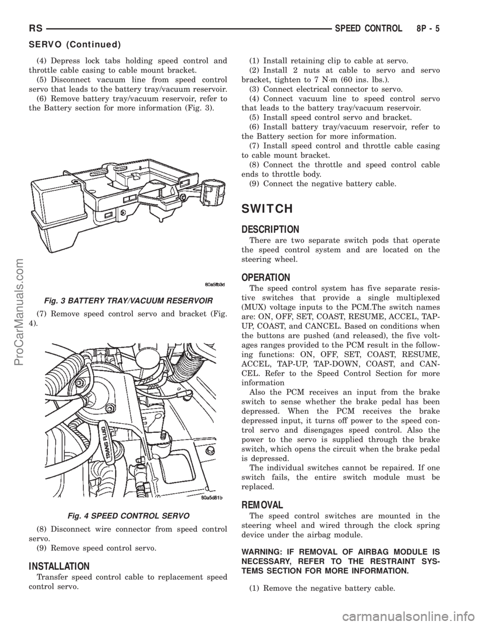
(6) Remove battery tray/vacuum reservoir, refer to
the Battery section for more information (Fig. 3).
(7) Remove speed control servo and bracket (Fig.
4).
(8) Disconnect wire connector from speed control
servo.
(9) Remove speed control servo.
INSTALLATION
Transfer speed control cable to replacement speed
control servo.(1) Install retaining clip to cable at servo.
(2) Install 2 nuts at cable to servo and servo
bracket, tighten to 7 N´m (60 ins. lbs.).
(3) Connect electrical connector to servo.
(4) Connect vacuum line to speed control servo
that leads to the battery tray/vacuum reservoir.
(5) Install speed control servo and bracket.
(6) Install battery tray/vacuum reservoir, refer to
the Battery section for more information.
(7) Install speed control and throttle cable casing
to cable mount bracket.
(8) Connect the throttle and speed control cable
ends to throttle body.
(9) Connect the negative battery cable.
SWITCH
DESCRIPTION
There are two separate switch pods that operate
the speed control system and are located on the
steering wheel.
OPERATION
The speed control system has five separate resis-
tive switches that provide a single multiplexed
(MUX) voltage inputs to the PCM.The switch names
are: ON, OFF, SET, COAST, RESUME, ACCEL, TAP-
UP, COAST, and CANCEL. Based on conditions when
the buttons are pushed (and released), the five volt-
ages ranges provided to the PCM result in the follow-
ing functions: ON, OFF, SET, COAST, RESUME,
ACCEL, TAP-UP, TAP-DOWN, COAST, and CAN-
CEL. Refer to the Speed Control Section for more
information
Also the PCM receives an input from the brake
switch to sense whether the brake pedal has been
depressed. When the PCM receives the brake
depressed input, it turns off power to the speed con-
trol servo and disengages speed control. Also the
power to the servo is supplied through the brake
switch, which opens the circuit when the brake pedal
is depressed.
The individual switches cannot be repaired. If one
switch fails, the entire switch module must be
replaced.
REMOVAL
The speed control switches are mounted in the
steering wheel and wired through the clock spring
device under the airbag module.
WARNING: IF REMOVAL OF AIRBAG MODULE IS
NECESSARY, REFER TO THE RESTRAINT SYS-
TEMS SECTION FOR MORE INFORMATION.
(1) Remove the negative battery cable.
Fig. 3 BATTERY TRAY/VACUUM RESERVOIR
Fig. 4 SPEED CONTROL SERVO
RSSPEED CONTROL8P-5
SERVO (Continued)
ProCarManuals.com
Page 631 of 2399

(2) Turn off ignition.
(3) Remove the air bag, refer to the restraint sec-
tion for more information.
(4) Remove the screw from bottom of the switch.
(5) Remove switch from steering wheel.
(6) Disconnect two-way electrical connector.
(7) Repeat for the other switch.
INSTALLATION
The speed control switches are mounted in the
steering wheel and wired through the clock spring
device under the airbag module.
WARNING: IF REMOVAL OF AIRBAG MODULE IS
NECESSARY, REFER TO THE RESTRAINT SYS-
TEMS SECTION FOR MORE INFORMATION.
(1) Connect two-way electrical connector.
(2) Install switch.
(3) Install screw for the switch.
(4) Repeat for the other switch.
(5) Install the air bag, refer to the restraint section
for more information.
(6) Install the negative battery cable.
VACUUM RESERVOIR
DESCRIPTION
The vacuum reservoir is located in the engine com-
partment. It is made of plastic.
OPERATION
The reservoir stores engine vacuum. Manifold vac-
uum is supplied from the brake booster check valve.
The speed control vacuum supply hose has a check
valve at the source (brake booster) to maintain the
highest available vacuum level in the servo, reservoir
and vacuum hoses. When engine vacuum drops, as in
climbing a grade while driving, the reservoir supplies
the vacuum needed to maintain proper speed control
operation. The vacuum reservoir cannot be repaired
and must be replaced if faulty.
REMOVAL
(1) Release hood latch and open hood.
(2) Disconnect the negative battery cable.
(3) Disconnect the vacuum line to the battery tray/
vacuum reservoir.
(4) Remove battery tray/vacuum reservoir, refer to
the Battery section for more information.
INSTALLATION
(1) Install battery tray/vacuum reservoir, refer to
the Battery section for more information.
(2) Connect vacuum line that leads to the battery
tray/vacuum reservoir.
(3) Connect the negative battery cable.
8P - 6 SPEED CONTROLRS
SWITCH (Continued)
ProCarManuals.com
Page 634 of 2399
DIAGNOSIS AND TESTING
DIAGNOSIS AND TESTING - SENTRY KEY
IMMOBILIZER SYSTEM
WARNING: ON VEHICLES EQUIPPED WITH AIR-
BAGS, REFER TO ELECTRICAL, RESTRAINTS,
WARNINGS, BEFORE ATTEMPTING COMPONENT
DIAGNOSIS OR SERVICE. FAILURE TO TAKE THE
PROPER PRECAUTIONS COULD RESULT IN ACCI-
DENTAL AIRBAG DEPLOYMENT AND POSSIBLE
PERSONAL INJURY.
NOTE: The following tests may not prove conclu-
sive in the diagnosis of this system. The most reli-
able, efficient, and accurate means to diagnose the
Sentry Key Immobilizer System involves the use of
a DRB IIITscan tool. Refer to the proper Body Diag-
nostic Procedures Manual.
The Sentry Key Immobilizer System (SKIS) and
the Programmable Communication Interface (PCI)
bus network should be diagnosed using a DRB IIIt
scan tool. The DRB IIItwill allow confirmation that
the PCI bus is functional, that the Sentry Key Immo-
bilizer Module (SKIM) is placing the proper messages
on the PCI bus, and that the Powertrain Control
Module (PCM) is receiving the PCI bus messages.
Refer to the proper Body Diagnostic Procedures man-
ual, and Wiring Diagrams for complete circuit
descriptions and diagrams.
(1) Check the fuses in the Integrated Power Mod-
ule (IPM). If OK, go to Step 2. If not OK, repair the
shorted circuit or component as required and replace
the faulty fuse.
(2) Disconnect and isolate the battery negative
remote cable from the remote terminal. Unplug the
wire harness connector at the SKIM. Check for con-
tinuity between the ground circuit cavity of the
SKIM wire harness connector and a good ground.
There should be continuity. If OK, go to Step 3. If not
OK, repair the open circuit to ground as required.
(3) Connect the battery negative cable. Check for
battery voltage at the fused B(+) circuit cavity of the
SKIM wire harness connector. If OK, go to Step 4. If
not OK, repair the open circuit to the fuse in the
IPM as required.
(4) Turn the ignition switch to the ON position.
Check for battery voltage at the fused ignition switch
output (run/start) circuit cavity of the SKIM wire
harness connector. If OK, use a DRB IIItscan tool
and the proper Body Diagnostic Procedures manual
to complete the diagnosis of the SKIS. If not OK,
repair the open circuit to the fuse in the IPM as
required.
DIAGNOSIS AND TESTING - VEHICLE THEFT
SECURITY SYSTEM
Refer to the appropriate wiring information. The
wiring information includes wiring diagrams, proper
wire and connector repair procedures, further details
on wire harness routing and retention, as well as
pin-out and location views for the various wire har-
ness connectors, splices and grounds. Using a DRB
IIItscan tool. Refer to the proper Body Diagnostic
Procedures Manual for test procedures.
HOOD AJAR SWITCH
REMOVAL
(1) Disconnect and isolate the battery negative
cable.
(2) Using a small flat blade screwdriver, pry trig-
ger switch from the bracket on the left fender well.
(3) Disconnect the hood ajar switch from the wire
connector and remove from vehicle.
INSTALLATION
(1) Connect the hood ajar switch to the wire conec-
tor.
(2) Press the hood ajar switch into position on the
bracket located on the left inner fender well.
(3) Reconnect the battery negative cable.
(4) Close the hood and check for proper operation.
TRANSPONDER KEY
DESCRIPTION
The Sentry Key Immobilizer System (SKIS) uses a
transponder chip that is integral to each ignition key
(Fig. 1) to communicate with the Sentry Key Immo-
bilizer Module (SKIM). Ignition keys are supplied
with the vehicle when it is shipped from the factory.
The transponder chip is undermolded within the
head of the key. This undermold is hidden beneath
an overmolded rubber cap.
OPERATION
Each Sentry Key has a unique transponder identi-
fication code permanently programmed into it by the
manufacturer. Likewise, the SKIM has a unique
9Secret Key9code programmed into it by the manu-
facturer as well. When a Sentry Key is programmed
into the memory of the SKIM, the SKIM stores the
transponder identification code from the Sentry Key,
and the Sentry Key learns the9Secret Key9code from
the SKIM. Once the Sentry Key learns the9Secret
Key9code of the SKIM, it is also permanently pro-
grammed into the transponder's memory. Therefore,
blank keys for the SKIS must be programmed by the
RSVEHICLE THEFT SECURITY8Q-3
VEHICLE THEFT SECURITY (Continued)
ProCarManuals.com
Page 648 of 2399
HEADLAMP WASHERS -
EXPORT
DESCRIPTION
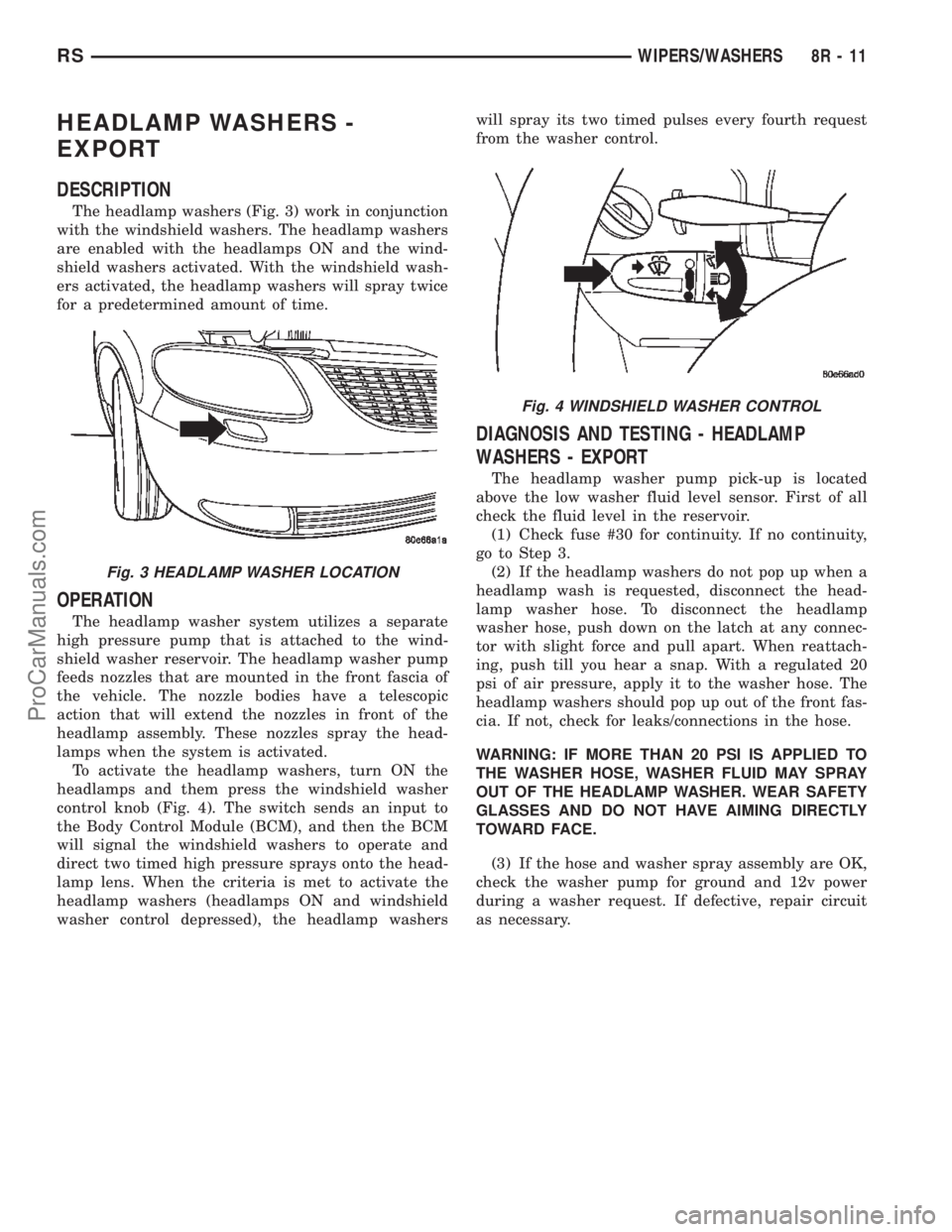
The headlamp washers (Fig. 3) work in conjunction
with the windshield washers. The headlamp washers
are enabled with the headlamps ON and the wind-
shield washers activated. With the windshield wash-
ers activated, the headlamp washers will spray twice
for a predetermined amount of time.
OPERATION
The headlamp washer system utilizes a separate
high pressure pump that is attached to the wind-
shield washer reservoir. The headlamp washer pump
feeds nozzles that are mounted in the front fascia of
the vehicle. The nozzle bodies have a telescopic
action that will extend the nozzles in front of the
headlamp assembly. These nozzles spray the head-
lamps when the system is activated.
To activate the headlamp washers, turn ON the
headlamps and them press the windshield washer
control knob (Fig. 4). The switch sends an input to
the Body Control Module (BCM), and then the BCM
will signal the windshield washers to operate and
direct two timed high pressure sprays onto the head-
lamp lens. When the criteria is met to activate the
headlamp washers (headlamps ON and windshield
washer control depressed), the headlamp washerswill spray its two timed pulses every fourth request
from the washer control.
DIAGNOSIS AND TESTING - HEADLAMP
WASHERS - EXPORT
The headlamp washer pump pick-up is located
above the low washer fluid level sensor. First of all
check the fluid level in the reservoir.
(1) Check fuse #30 for continuity. If no continuity,
go to Step 3.
(2) If the headlamp washers do not pop up when a
headlamp wash is requested, disconnect the head-
lamp washer hose. To disconnect the headlamp
washer hose, push down on the latch at any connec-
tor with slight force and pull apart. When reattach-
ing, push till you hear a snap. With a regulated 20
psi of air pressure, apply it to the washer hose. The
headlamp washers should pop up out of the front fas-
cia. If not, check for leaks/connections in the hose.
WARNING: IF MORE THAN 20 PSI IS APPLIED TO
THE WASHER HOSE, WASHER FLUID MAY SPRAY
OUT OF THE HEADLAMP WASHER. WEAR SAFETY
GLASSES AND DO NOT HAVE AIMING DIRECTLY
TOWARD FACE.
(3) If the hose and washer spray assembly are OK,
check the washer pump for ground and 12v power
during a washer request. If defective, repair circuit
as necessary.
Fig. 3 HEADLAMP WASHER LOCATION
Fig. 4 WINDSHIELD WASHER CONTROL
RSWIPERS/WASHERS8R-11
ProCarManuals.com
Page 650 of 2399
REMOVAL
(1) Disconnect and isolate the battery negative
cable.
(2) Hoist vehicle or support on jack stands.
(3) Disconnect the hose from the nozzle inlet. To
disconnect the headlamp washer hose, push down on
the latch with slight force and pull apart.
(4) Apply a regulated 20 psi of compressed air to
the inlet, so as to fully extend the telescopic unit.
WARNING: IF MORE THAN 20 PSI IS APPLIED TO
THE WASHER INLET, WASHER FLUID MAY SPRAY
OUT OF THE HEADLAMP WASHER. WEAR SAFETY
GLASSES AND DO NOT HAVE AIMING DIRECTLY
TOWARD FACE.
(5) Unsnap cover from telescopic assembly.
(6) Disconnect air supply from washer inlet to fully
retract the telescopic unit.
(7) Remove two screws holding the nozzle assem-
bly to the front fascia.
(8) Remove the nozzle assembly from behind fas-
cia.
INSTALLATION
(1) Place the nozzle assembly in behind the fascia.
(2) Install the two screws holding the nozzle
assembly to the front fascia.
(3) Snap cover onto telescopic assembly.
WARNING: IF MORE THAN 20 PSI IS APPLIED TO
THE WASHER INLET, WASHER FLUID MAY SPRAY
OUT OF THE HEADLAMP WASHER. WEAR SAFETY
GLASSES AND DO NOT HAVE AIMING DIRECTLY
TOWARD FACE.
On the new washer unit, there is a white tab with
pull ring holding the telescopic unit up approxi-
mately an inch. This is to ease the installation pro-
cess. Once cover is snapped on, you may either pull
up on the unit to remove the tab, or apply regulated
compressed air.
(4) Apply a regulated 20 psi of compressed air the
inlet, so as to fully extend the telescopic unit.
(5) With unit extended, pull white tab out from the
bottom of the telescopic unit and discard.
(6) Remove the air supply from the washer unit.
(7) Connect the washer hose to the telescopic unit.
Press firmly until snap is heard.
(8) Remove vehicle from hoist or jack stands.
(9) Connect the battery negative cable.
(10) Verify vehicle and system operation.
HEADLAMP WASHER HOSE -
EXPORT
REMOVAL
The headlamp washer hose is a special high pres-
sure hose with specific fittings, and must be replaced
as a unit.
(1) Disconnect and isolate the battery negative
cable.
(2) Hoist vehicle or support on jack stands.
(3) Remove parts as necessary to replace high
pressure headlamp washer hose. When disconnecting
hose, press down firmly on latch at headlamp washer
pump motor and telescopic washer assembly and pull
apart.
INSTALLATION
The headlamp washer hose is a special high pres-
sure hose with specific fittings, and must be replaced
as a unit.
(1) Install the new high pressure headlamp
washer hose assembly. Push fitting on until a snap is
heard.
(2) Install the parts that were removed to replace
high pressure headlamp washer hose.
(3) Remove vehicle from hoist or jack stands.
(4) Connect the battery negative cable.
(5) Verify vehicle and system operation.
HEADLAMP WASHER PUMP
MOTOR - EXPORT
REMOVAL
(1) Disconnect and isolate the battery negative
cable.
(2) Remove the engine fresh air housing inside the
engine compartment (Refer to 9 - ENGINE/AIR
INTAKE SYSTEM/AIR CLEANER HOUSING -
REMOVAL).
(3) Disconnect the washer hose at the in-line con-
nector forward of the cowl grille so that the in-line
connector remains with the washer hose from the
fresh air plenum.
(4) Disconnect the washer hose from the hose clip
located on the front fender side shield.
(5) Remove the filler tube screw.
(6) Hoist and support vehicle on hoist or jack
stands.
(7) Remove the right front wheel and tire assembly
(Refer to 22 - TIRES/WHEELS - REMOVAL).
(8) Disconnect the left right front wheelhouse
splash shield and move aside (Refer to 23 - BODY/
EXTERIOR/WHEELHOUSE SPLASH SHIELD -
REMOVAL).
RSWIPERS/WASHERS8R-13
HEADLAMP WASHERS - EXPORT (Continued)
ProCarManuals.com
Page 660 of 2399

8W-01 WIRING DIAGRAM INFORMATION
TABLE OF CONTENTS
page page
WIRING DIAGRAM INFORMATION
DESCRIPTION
DESCRIPTION - HOW TO USE WIRING
DIAGRAMS...........................1
DESCRIPTION - CIRCUIT INFORMATION....5
DESCRIPTION - CIRCUIT FUNCTIONS......6
DESCRIPTION - SECTION IDENTIFICATION
AND INFORMATION....................6
DESCRIPTION - CONNECTOR, GROUND
AND SPLICE INFORMATION..............7
WARNING
WARNINGS - GENERAL.................7
DIAGNOSIS AND TESTING - WIRING
HARNESS............................7
STANDARD PROCEDURE
STANDARD PROCEDURE -
ELECTROSTATIC DISCHARGE (ESD)
SENSITIVE DEVICES...................8
STANDARD PROCEDURE - TESTING OF
VOLTAGE POTENTIAL...................9
STANDARD PROCEDURE - TESTING FOR
CONTINUITY..........................9STANDARD PROCEDURE - TESTING FOR A
SHORT TO GROUND...................9
STANDARD PROCEDURE - TESTING FOR A
SHORT TO GROUND ON FUSES
POWERING SEVERAL LOADS...........10
STANDARD PROCEDURE - TESTING FOR A
VOLTAGE DROP......................10
SPECIAL TOOLS
WIRING/TERMINAL....................10
CONNECTOR
REMOVAL.............................11
INSTALLATION.........................11
DIODE
REMOVAL.............................14
INSTALLATION.........................14
TERMINAL
REMOVAL.............................14
INSTALLATION.........................14
WIRE
STANDARD PROCEDURE - WIRE SPLICING . . 15
WIRING DIAGRAM
INFORMATION
DESCRIPTION
DESCRIPTION - HOW TO USE WIRING
DIAGRAMS
DaimlerChrysler Corporation wiring diagrams are
designed to provide information regarding the vehi-
cles wiring content. In order to effectively use the
wiring diagrams to diagnose and repair
DaimlerChrysler Corporation vehicles, it is important
to understand all of their features and characteris-
tics.
Diagrams are arranged such that the power (B+)
side of the circuit is placed near the top of the page,
and the ground (B-) side of the circuit is placed near
the bottom of the page (Fig. 1).
All switches, components, and modules are shown
in the at rest position with the doors closed and the
key removed from the ignition (Fig. 2).Components are shown two ways. A solid line
around a component indicates that the component is
complete. A dashed line around the component indi-
cates that the component is being shown is not com-
plete. Incomplete components have a reference
number to indicate the page where the component is
shown complete.
It is important to realize that no attempt is made
on the diagrams to represent components and wiring
as they appear on the vehicle. For example, a short
piece of wire is treated the same as a long one. In
addition, switches and other components are shown
as simply as possible, with regard to function only.
SYMBOLS
International symbols are used throughout the wir-
ing diagrams. These symbols are consistent with
those being used around the world (Fig. 3).
RS8W-01 WIRING DIAGRAM INFORMATION8W-01-1
ProCarManuals.com
Page 666 of 2399

DESCRIPTION - CONNECTOR, GROUND AND
SPLICE INFORMATION
CAUTION: Not all connectors are serviced. Some
connectors are serviced only with a harness. A typ-
ical example might be the Supplemental Restraint
System connectors. Always check parts availability
before attempting a repair.
IDENTIFICATION
In-line connectors are identified by a number, as
follows:
²In-line connectors located in the engine compart-
ment are C100 series numbers
²In-line connectors located in the Instrument
Panel area are C200 series numbers.
²In-line connectors located in the body are C300
series numbers.
²Jumper harness connectors are C400 series
numbers.
²Grounds and ground connectors are identified
with a ªGº and follow the same series numbering as
the in-line connectors.
²Splices are identified with an ªSº and follow the
same series numbering as the in-line connectors.
²Component connectors are identified by the com-
ponent name instead of a number. Multiple connec-
tors on a component use a C1, C2, etc. identifier.
LOCATIONS
Section 8W-91 contains connector/ground/splice
location illustrations. The illustrations contain the
connector name (or number)/ground number/splice
number and component identification. Connector/
ground/splice location charts in section 8W-91 refer-
ence the figure numbers of the illustrations.
The abbreviation T/O is used in the component
location section to indicate a point in which the wir-
ing harness branches out to a component. The abbre-
viation N/S means Not Shown in the illustrations
WARNING
WARNINGS - GENERAL
WARNINGSprovide information to prevent per-
sonal injury and vehicle damage. Below is a list of
general warnings that should be followed any time a
vehicle is being serviced.
WARNING: ALWAYS WEAR SAFETY GLASSES FOR
EYE PROTECTION.
WARNING: USE SAFETY STANDS ANYTIME A PRO-
CEDURE REQUIRES BEING UNDER A VEHICLE.WARNING: BE SURE THAT THE IGNITION SWITCH
ALWAYS IS IN THE OFF POSITION, UNLESS THE
PROCEDURE REQUIRES IT TO BE ON.
WARNING: SET THE PARKING BRAKE WHEN
WORKING ON ANY VEHICLE. AN AUTOMATIC
TRANSMISSION SHOULD BE IN PARK. A MANUAL
TRANSMISSION SHOULD BE IN NEUTRAL.
WARNING: OPERATE THE ENGINE ONLY IN A
WELL-VENTILATED AREA.
WARNING: KEEP AWAY FROM MOVING PARTS
WHEN THE ENGINE IS RUNNING, ESPECIALLY THE
FAN AND BELTS.
WARNING: TO PREVENT SERIOUS BURNS, AVOID
CONTACT WITH HOT PARTS SUCH AS THE RADIA-
TOR, EXHAUST MANIFOLD(S), TAIL PIPE, CATA-
LYTIC CONVERTER AND MUFFLER.
WARNING: DO NOT ALLOW FLAME OR SPARKS
NEAR THE BATTERY. GASES ARE ALWAYS
PRESENT IN AND AROUND THE BATTERY.
WARNING: ALWAYS REMOVE RINGS, WATCHES,
LOOSE HANGING JEWELRY AND AVOID LOOSE
CLOTHING.
DIAGNOSIS AND TESTING - WIRING HARNESS
TROUBLESHOOTING TOOLS
When diagnosing a problem in an electrical circuit
there are several common tools necessary. These tools
are listed and explained below.
²Jumper Wire - This is a test wire used to con-
nect two points of a circuit. It can be used to bypass
an open in a circuit.
WARNING: NEVER USE A JUMPER WIRE ACROSS
A LOAD, SUCH AS A MOTOR, CONNECTED
BETWEEN A BATTERY FEED AND GROUND.
²Voltmeter - Used to check for voltage on a cir-
cuit. Always connect the black lead to a known good
ground and the red lead to the positive side of the
circuit.
CAUTION: Most of the electrical components used
in today's vehicles are Solid State. When checking
voltages in these circuits, use a meter with a 10 -
megohm or greater impedance rating.
RS8W-01 WIRING DIAGRAM INFORMATION8W-01-7
WIRING DIAGRAM INFORMATION (Continued)
ProCarManuals.com
Page 1201 of 2399
WARNING: ON VEHICLES EQUIPPED WITH AIR-
BAGS, REFER TO RESTRAINTS BEFORE ATTEMPT-
ING ANY STEERING WHEEL, STEERING COLUMN,
SEAT OR INSTRUMENT PANEL COMPONENT DIAG-
NOSIS OR SERVICE. FAILURE TO TAKE THE
PROPER PRECAUTIONS COULD RESULT IN ACCI-
DENTAL AIRBAG DEPLOYMENT AND POSSIBLE
PERSONAL INJURY.
(1) Check the fused B(+) fuse in the Integrated
Power Module (IPM). If OK, go to Step 2. If not OK,
repair the shorted circuit or component as required
and replace the faulty fuse.
(2) Check for battery voltage at the fused B(+) fuse
in the IPM. If OK, go to Step 3. If not OK, repair the
open fused B(+) circuit to the IPM fuse as required.
(3)
Open the power outlet door. Check for continuity
between the inside circumference of the power outlet
receptacle and a good ground. There should be continu-
ity. If OK, go to Step 4. If not OK, go to Step 5.
(4) Check for battery voltage at the insulated con-
tact located at the back of the power outlet recepta-
cle. If not OK, go to Step 5.
(5) Disconnect and isolate the battery negative
cable. Remove the appropriate bezel. Check for conti-
nuity between the ground circuit cavity of the power
outlet wire harness connector and a good ground.
There should be continuity. If OK, go to Step 6. If not
OK, repair the open ground circuit to ground as
required.
(6) Connect the battery negative cable. Check for
battery voltage at the fused B(+) circuit cavity of the
power outlet wire harness connector. If OK, replace
the faulty power outlet receptacle. If not OK, repair
the open fused B(+) circuit to the IPM fuse as
required.
REMOVAL
(1) Disconnect and isolate the battery negative
cable.
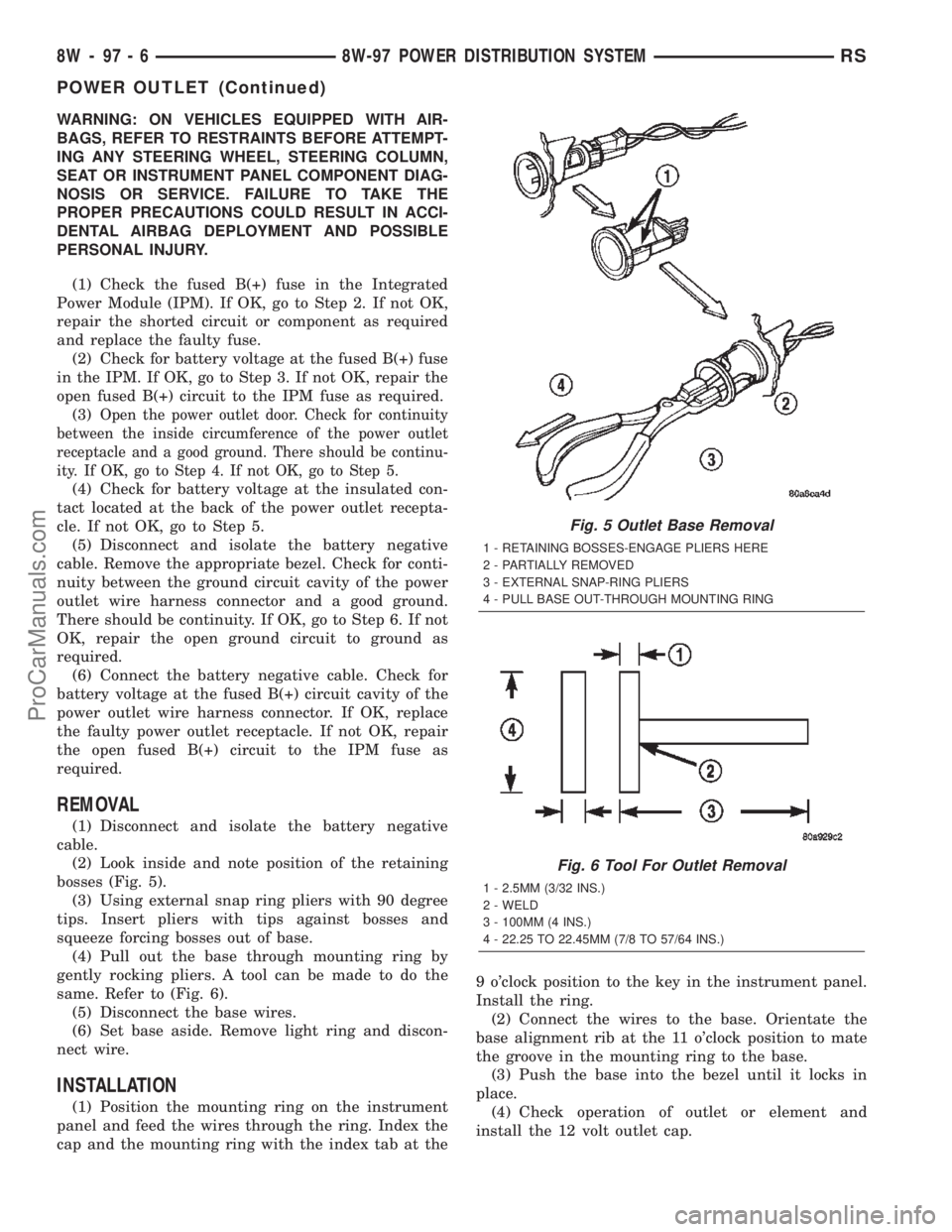
(2) Look inside and note position of the retaining
bosses (Fig. 5).
(3) Using external snap ring pliers with 90 degree
tips. Insert pliers with tips against bosses and
squeeze forcing bosses out of base.
(4) Pull out the base through mounting ring by
gently rocking pliers. A tool can be made to do the
same. Refer to (Fig. 6).
(5) Disconnect the base wires.
(6) Set base aside. Remove light ring and discon-
nect wire.
INSTALLATION
(1) Position the mounting ring on the instrument
panel and feed the wires through the ring. Index the
cap and the mounting ring with the index tab at the9 o'clock position to the key in the instrument panel.
Install the ring.
(2) Connect the wires to the base. Orientate the
base alignment rib at the 11 o'clock position to mate
the groove in the mounting ring to the base.
(3) Push the base into the bezel until it locks in
place.
(4) Check operation of outlet or element and
install the 12 volt outlet cap.
Fig. 5 Outlet Base Removal
1 - RETAINING BOSSES-ENGAGE PLIERS HERE
2 - PARTIALLY REMOVED
3 - EXTERNAL SNAP-RING PLIERS
4 - PULL BASE OUT-THROUGH MOUNTING RING
Fig. 6 Tool For Outlet Removal
1 - 2.5MM (3/32 INS.)
2 - WELD
3 - 100MM (4 INS.)
4 - 22.25 TO 22.45MM (7/8 TO 57/64 INS.)
8W - 97 - 6 8W-97 POWER DISTRIBUTION SYSTEMRS
POWER OUTLET (Continued)
ProCarManuals.com