warning CHRYSLER CARAVAN 2002 Service Manual
[x] Cancel search | Manufacturer: CHRYSLER, Model Year: 2002, Model line: CARAVAN, Model: CHRYSLER CARAVAN 2002Pages: 2399, PDF Size: 57.96 MB
Page 1388 of 2399

(22) Install right engine mount (Refer to 9 -
ENGINE/ENGINE MOUNTING/RIGHT MOUNT -
INSTALLATION).
(23) Install generator (Refer to 8 - ELECTRICAL/
CHARGING/GENERATOR - INSTALLATION).
(24) Install accessory drive belt (Refer to 7 -
COOLING/ACCESSORY DRIVE/DRIVE BELTS -
INSTALLATION).
(25) Install power steering belt (Refer to 7 -
COOLING/ACCESSORY DRIVE/DRIVE BELTS -
INSTALLATION).
(26) Install air cleaner housing assembly.
(27) Remove crankshaft and both camshaft locking
pins (Refer to 9 - ENGINE/VALVE TIMING - STAN-
DARD PROCEDURE).
(28) Refill cooling system (Refer to 7 - COOLING/
ENGINE/COOLANT - STANDARD PROCEDURE).
(29) Install engine cover (Refer to 9 - ENGINE -
INSTALLATION).
(30) Install front wiper unit (Refer to 8 - ELEC-
TRICAL/WIPERS/WASHERS/WIPER MODULE -
INSTALLATION).
(31) Connect negative battery cable.
CAMSHAFT OIL SEAL(S)
REMOVAL
(1) Disconnect negative battery cable.
(2) Remove air cleaner housing assembly.
(3) Support engine and remove right engine mount
(Refer to 9 - ENGINE/ENGINE MOUNTING/RIGHT
MOUNT - REMOVAL).
(4) Remove outer timing belt cover (Refer to 9 -
ENGINE/VALVE TIMING/TIMING BELT / CHAIN
COVER(S) - REMOVAL).
WARNING: Before removing the timing belt the
engine must put at 90É after TDC. Failure to do so
could result in valve and/or piston damage during
reassembly. (Refer to 9 - ENGINE/VALVE TIMING -
STANDARD PROCEDURE)
(5) Remove timing belt (Refer to 9 - ENGINE/
VALVE TIMING/TIMING BELT/CHAIN AND
SPROCKETS - REMOVAL).
(6) Using VM.1055, remove both camshaft gears
(Fig. 28).
(7) Remove both camshaft oil seals.
INSTALLATION
(1) Install new camshaft oil seal using VM.1057.
(2) Install camshaft sprockets and tighten retain-
ing bolts finger tight.
(3) Install timing belt (Refer to 9 - ENGINE/
VALVE TIMING/TIMING BELT/CHAIN AND
SPROCKETS - INSTALLATION) .(4) Torque camshaft sprockets to 108 N´m using
VM.1055 (Fig. 28).
(5) Install outer timing belt cover (Refer to 9 -
ENGINE/VALVE TIMING/TIMING BELT / CHAIN
COVER(S) - INSTALLATION).
(6) Install right engine mount (Refer to 9 -
ENGINE/ENGINE MOUNTING/RIGHT MOUNT -
INSTALLATION).
(7) Install air cleaner housing assembly.
(8) Connect negative battery cable.
ROCKER ARMS
DESCRIPTION
The rocker arms are made of stamped steel (Fig.
29).
OPERATION
The rocker arms are used as a link between the
camshaft and valves. As the camshaft rotates the
lobes of the camshafts apply downward pressure on
the rocker arms. This pressure is then transmitted to
the valves which causes the valves to open.
REMOVAL
(1) Disconnect negative battery cable.
Fig. 28 CAMSHAFT GEAR REMOVAL/INSTALLATION
1 - TIMING BELT INNER COVER
2 - CAMSHAFT SPROCKET
3 - IDLER PULLEYS
4 - CAMSHAFT SPROCKET
5 - VM.1055
RGENGINE9a-27
CYLINDER HEAD COVER(S) (Continued)
ProCarManuals.com
Page 1425 of 2399

OPERATION
The exhaust system contains, quiets, and cleans
the exhaust gases generated by the engine.
DIAGNOSIS AND TESTING
DIAGNOSIS AND TESTING - EXCESSIVE
EXHAUST SYSTEM NOISE
CONDITION POSSIBLE CAUSES CORRECTION
EXCESSIVE EXHAUST NOISE
(UNDER HOOD)1. Exhaust manifold cracked or
broken.1. Replace manifold.
2. Manifold to cylinder head leak. 2. Tighten manifold and/or replace
gasket.
3. EGR Valve to manifold gasket
leakage.3. Tighten fasteners or replace
gasket.
4. EGR Valve to EGR tube gasket
leakage.4. Tighten fasteners or replace
gasket.
5. EGR tube to manifold tube
leakage.5. Tighten tube nut.
6. Exhaust flex-joint to manifold
leak.6. Tighten joint fasteners and/or
replace gasket.
7. Exhaust flex-joint. 7. Replace catalytic converter
assembly.
8. Pipe and shell noise from front
exhaust pipe.8. Characteristic of single wall pipe.
EXCESSIVE EXHAUST NOISE 1. Leak at exhaust pipe joints. 1. Tighten clamps at leaking joints.
2. Burned or rusted out muffler
assembly or exhaust pipe.2. Replace muffler resonator tailpipe
assembly or exhaust pipe with
catalytic converter assembly.
3. Burned or rusted out resonator. 3. Replace muffler resonator tailpipe
assembly.
4. Restriction in exhaust system. 4. Perform Exhaust System
Restriction Check. Replace
component as necessary.
5. Converter material in muffler. 5. Replace muffler and converter
assemblies. Check fuel injection and
ignition systems for proper
operation.
DIAGNOSIS AND TESTING - EXHAUST SYSTEM
RESTRICTION CHECK
Exhaust system restriction can be checked by mea-
suring back pressure using the DRB IIItand PEP
module pressure tester.WARNING: THE NORMAL OPERATING TEMPERA-
TURE OF THE EXHAUST SYSTEM IS VERY HIGH.
THEREFORE, NEVER WORK AROUND OR ATTEMPT
TO SERVICE ANY PART OF THE EXHAUST SYSTEM
UNTIL IT IS COOLED. SPECIAL CARE SHOULD BE
TAKEN WHEN WORKING NEAR THE CATALYTIC
CONVERTER. THE TEMPERATURE OF THE CON-
VERTER RISES TO A HIGH LEVEL AFTER A SHORT
PERIOD OF ENGINE OPERATION TIME.
11 - 2 EXHAUST SYSTEMRS
EXHAUST SYSTEM (Continued)
ProCarManuals.com
Page 1429 of 2399
INSPECTION
WARNING: THE NORMAL OPERATING TEMPERA-
TURE OF THE EXHAUST SYSTEM IS VERY HIGH.
THEREFORE, NEVER ATTEMPT TO SERVICE ANY
PART OF THE EXHAUST SYSTEM UNTIL IT IS
COOLED. SPECIAL CARE SHOULD BE TAKEN
WHEN WORKING NEAR THE CATALYTIC CON-
VERTER. THE TEMPERATURE OF THE CONVERTER
RISES TO A HIGH LEVEL AFTER A SHORT PERIOD
OF ENGINE OPERATION TIME.
Check catalytic converter for a flow restriction.
(Refer to 11 - EXHAUST SYSTEM - DIAGNOSIS
AND TESTING) Exhaust System Restriction Check
for procedure.
Visually inspect the catalytic converter element by
using a borescope or equivalent. Remove oxygen sen-
sor(s) and insert borescope. If borescope is not avail-
able, remove converter and inspect element using a
flashlight. Inspect element for cracked or melted sub-
strate.
NOTE: Before replacing a catalytic converter, deter-
mine the root cause of failure. Most catalytic con-
verter failures are caused by air, fuel or ignition
problems. (Refer to Appropriate Diagnostic Informa-
tion) for test procedures.
INSTALLATION
(1) Position new gasket onto the manifold flange
and install catalytic converter (Fig. 5). Tighten fas-
teners to 37 N´m (325 in. lbs.).
NOTE: Be careful not to twist or kink the oxygen
sensor wires.
(2) Install (if removed) and connect the down-
stream oxygen sensor (Fig. 4).
(3) Install the muffler/resonator assembly. (Refer
to 11 - EXHAUST SYSTEM/MUFFLER - INSTALLA-
TION)
CROSS-OVER PIPE - 3.3/3.8L
REMOVAL
(1) Disconnect negative cable from battery.
(2) Remove the fasteners attaching the left bank
manifold connection to cross-over pipe (Fig. 6).
(3) Raise vehicle and remove the left front wheel.
(4) Access the lower right bank pipe connection
fastener through the left front wheel opening using a
long ratchet extension. Loosen and remove the lower
fastener.(5) Remove the upper right bank pipe connection
fastener by accessing though the catalytic converter
floor pan tunnel.
(6) Lower the vehicle.
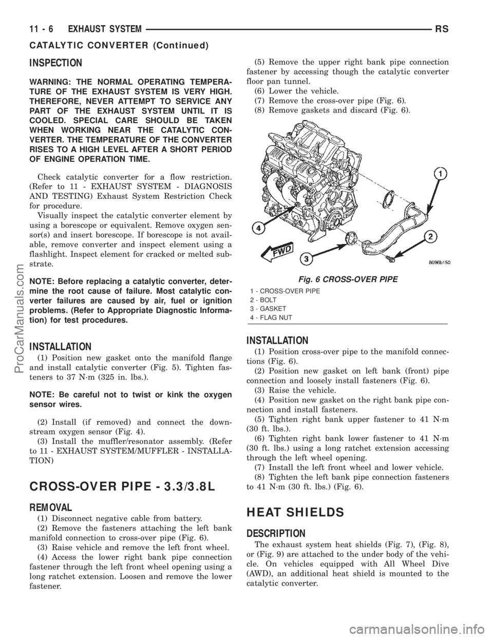
(7) Remove the cross-over pipe (Fig. 6).
(8) Remove gaskets and discard (Fig. 6).
INSTALLATION
(1) Position cross-over pipe to the manifold connec-
tions (Fig. 6).
(2) Position new gasket on left bank (front) pipe
connection and loosely install fasteners (Fig. 6).
(3) Raise the vehicle.
(4) Position new gasket on the right bank pipe con-
nection and install fasteners.
(5) Tighten right bank upper fastener to 41 N´m
(30 ft. lbs.).
(6) Tighten right bank lower fastener to 41 N´m
(30 ft. lbs.) using a long ratchet extension accessing
through the left wheel opening.
(7) Install the left front wheel and lower vehicle.
(8) Tighten the left bank pipe connection fasteners
to 41 N´m (30 ft. lbs.) (Fig. 6).
HEAT SHIELDS
DESCRIPTION
The exhaust system heat shields (Fig. 7), (Fig. 8),
or (Fig. 9) are attached to the under body of the vehi-
cle. On vehicles equipped with All Wheel Dive
(AWD), an additional heat shield is mounted to the
catalytic converter.
Fig. 6 CROSS-OVER PIPE
1 - CROSS-OVER PIPE
2 - BOLT
3 - GASKET
4 - FLAG NUT
11 - 6 EXHAUST SYSTEMRS
CATALYTIC CONVERTER (Continued)
ProCarManuals.com
Page 1448 of 2399
SPECIFICATIONS - TORQUE
DESCRIPTION N´m Ft. Lbs. In. Lbs.
Front Cradle Crossmember to Fram Rail Attaching Bolts (4) 163 120 Ð
Reinforcement Plate to Crossmember Attaching Bolt Size M14 (9) 153 113 Ð
Reinforcement Plate to Crossmember Attaching Bolt Size M12 (1) 106 78 Ð
Reinforcement Plate to Crossmember Attaching Bolt Size M10 (4) 61 45 Ð
Rear Engine Mount to Crossmember Attaching Through Bolt 68 50 Ð
Radiator Support Crossmember Attaching Bolts 51 38 Ð
FRONT CRADLE
CROSSMEMBER
DESCRIPTION
DESCRIPTION - FRONT CRADLE
CROSSMEMBER
This vehicle uses a one piece cast aluminum cradle
for the front cradle crossmember. The cradle cross-
member is used as the attaching points for the lower
control arms, stabilizer bar and steering gear. The
cradle also has the power steering hoses and the
chassis brake tubes attached to it.
WARNING: If a threaded hole in the suspension cra-
dle needs to be repaired, only use the type of
thread insert and installation procedure specified
for this application.
The threaded holes in the front cradle crossmem-
ber that are used for attachment of the lower control
arm rear bushing retainer, power steering hose and
chassis brake tubes can be repaired. The repair is
done by the installation of a Heli-Coiltthread insert
which has been specifically developed for this appli-
cation. Refer to the Mopar Parts Catalog for the spec-
ified Heli-Coiltthread insert to be used for this
application. The procedure for installing the Heli-
Coiltthread insert is detailed in the Service Proce-
dures section in this group of the service manual.
DESCRIPTION - FRONT CRADLE
CROSSMEMBER THREAD REPAIR
WARNING: When performing this procedure use
only the thread inserts which are specified in the
Mopar Parts Catalog for this repair procedure.
These thread inserts have been specifically devel-
oped for this application and use of other types of
thread inserts can result in an inferior long term
repair.The threaded holes in the front cradle crossmem-
ber, if damaged, can repaired by installing a Heli-
Coiltthread insert.
The threaded holes that are repairable using the
thread insert, are the lower control arm rear bushing
retainer mounting bolt holes, routing bracket attach-
ing locations for the power steering hoses, and brake
hose attachment holes.
This repair procedure now allows the threaded
holes in the cradle crossmember to be repaired, elim-
inating the need to replace the cradle crossmember if
damage occurs to one of the threaded holes.
The thread inserts for this application are specified
by part number in the Mopar Parts Catalog.Do not
use a substitute thread insert.
The specific tools and equipment required to install
the thread insert are listed below. Refer to the
instructions included with the thread insert for the
detailed procedure used for the installation of the
thread insert.
NOTE: The thread inserts for this application are for
the repair of M8x1.25 and M10x1.5 threads. Be sure
the correct tools are used for the required thread
insert size.
TOOL REQUIREMENT FOR M8x1.25 Thread
²8.3mm (5/16 in.) Drill Bit
²120É Countersink
²Heli-CoiltTap #4863-8
²Heli-CoiltGage #4624-8
²Heli-CoiltHand Inserting Tool 7751-8
²Needle Nose Pliers ± For Removal Of Thread
Insert Driving Tang
TOOL REQUIREMENT FOR M10x1.5 Thread
²10.5mm (25/64 in.) Drill Bit
²120É Countersink
²Heli-CoiltTap #4863-10
²Heli-CoiltGage #4624-10
²Heli-CoiltHand Inserting Tool 7751-10
²Needle Nose Pliers ± For Removal Of Thread
Insert Driving Tang
RSFRAME & BUMPERS13-9
FRAME (Continued)
ProCarManuals.com
Page 1457 of 2399
INSTALLATION
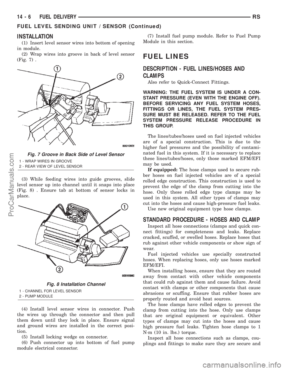
(1) Insert level sensor wires into bottom of opening
in module.
(2) Wrap wires into groove in back of level sensor
(Fig. 7) .
(3) While feeding wires into guide grooves, slide
level sensor up into channel until it snaps into place
(Fig. 8) . Ensure tab at bottom of sensor locks in
place.
(4) Install level sensor wires in connector. Push
the wires up through the connector and then pull
them down until they lock in place. Ensure signal
and ground wires are installed in the correct posi-
tion.
(5) Install locking wedge on connector.
(6) Push connector up into bottom of fuel pump
module electrical connector.(7) Install fuel pump module. Refer to Fuel Pump
Module in this section.
FUEL LINES
DESCRIPTION - FUEL LINES/HOSES AND
CLAMPS
Also refer to Quick-Connect Fittings.
WARNING: THE FUEL SYSTEM IS UNDER A CON-
STANT PRESSURE (EVEN WITH THE ENGINE OFF).
BEFORE SERVICING ANY FUEL SYSTEM HOSES,
FITTINGS OR LINES, THE FUEL SYSTEM PRES-
SURE MUST BE RELEASED. REFER TO THE FUEL
SYSTEM PRESSURE RELEASE PROCEDURE IN
THIS GROUP.
The lines/tubes/hoses used on fuel injected vehicles
are of a special construction. This is due to the
higher fuel pressures and the possibility of contami-
nated fuel in this system. If it is necessary to replace
these lines/tubes/hoses, only those marked EFM/EFI
may be used.
If equipped:The hose clamps used to secure rub-
ber hoses on fuel injected vehicles are of a special
rolled edge construction. This construction is used to
prevent the edge of the clamp from cutting into the
hose. Only these rolled edge type clamps may be
used in this system. All other types of clamps may
cut into the hoses and cause high-pressure fuel leaks.
Use new original equipment type hose clamps.
STANDARD PROCEDURE - HOSES AND CLAMP
Inspect all hose connections (clamps and quick con-
nect fittings) for completeness and leaks. Replace
cracked, scuffed, or swelled hoses. Replace hoses that
rub against other vehicle components or show sign of
wear.
Fuel injected vehicles use specially constructed
hoses. When replacing hoses, only use hoses marked
EFM/EFI.
When installing hoses, ensure that they are routed
away from contact with other vehicle components
that could rub against them and cause failure. Avoid
contact with clamps or other components that cause
abrasions or scuffing. Ensure that rubber hoses are
properly routed and avoid heat sources.
The hose clamps have rolled edges to prevent the
clamp from cutting into the hose. Only use clamps
that are original equipment or equivalent. Other
types of clamps may cut into the hoses and cause
high pressure fuel leaks. Tighten hose clamps to 1
N´m (10 in. lbs.) torque.
Inspect all hose connections such as clamps, cou-
plings and fittings to make sure they are secure and
Fig. 7 Groove in Back Side of Level Sensor
1 - WRAP WIRES IN GROOVE
2 - REAR VIEW OF LEVEL SENSOR
Fig. 8 Installation Channel
1 - CHANNEL FOR LEVEL SENSOR
2 - PUMP MODULE
14 - 6 FUEL DELIVERYRS
FUEL LEVEL SENDING UNIT / SENSOR (Continued)
ProCarManuals.com
Page 1459 of 2399

FUEL PUMP MODULE
DESCRIPTION
The fuel pump module is installed in the top of the
fuel tank (Fig. 10) .
The fuel pump module contains the following:
²Electric fuel pump
²Fuel pump reservoir
²Inlet strainer
²Fuel pressure regulator
²Fuel gauge sending unit
²Fuel supply line connection
The inlet strainer, fuel pressure regulator
and fuel level sensor are the only serviceable
items. If the fuel pump or electrical wiring har-
ness requires service, replace the fuel pump
module.
The electric fuel pump is located in and is part of
the fuel pump module. It is a positive displacement,
gerotor type, immersible pump with a permanent
magnet electric motor.
OPERATION
The pump draws fuel through a strainer and
pushes it through the motor to the outlet. The pump
contains one check valve. The check valve, in the
pump outlet, maintains pump pressure during engine
off conditions. The fuel pump relay provides voltage
to the fuel pump.
The fuel pump has a maximum deadheaded pres-
sure output of approximately 880 kPa (130 psi). The
regulator adjusts fuel system pressure to approxi-
mately 400 34 kPa (58 5 psi).
FUEL PUMP ELECTRICAL CONTROL
Voltage to operate the electric pump is supplied
through the fuel pump relay. For an electrical opera-tional description of the fuel pump refer to fuel Pump
RelayÐPCM Output.
ELECTRICAL PUMP REPLACEMENT
The electric fuel pump is not serviceable. If the
fuel pump or electrical wiring harness needs replace-
ment, the complete fuel pump module must be
replaced. Perform the Fuel System Pressure Release
procedure before servicing the fuel pump.
REMOVAL
WARNING: RELEASE FUEL SYSTEM PRESSURE
BEFORE SERVICING FUEL SYSTEM COMPONENTS.
SERVICE VEHICLES IN WELL VENTILATED AREAS
AND AVOID IGNITION SOURCES. NEVER SMOKE
WHILE SERVICING THE VEHICLE.
(1) Remove fuel filler cap and perform Fuel Sys-
tem Pressure Release procedure.
(2) Disconnect negative cable from auxiliary
jumper terminal.
(3) Drain fuel tank, refer to the Fuel Tank proce-
dure in the Fuel Delivery section.
(4) Remove fuel tank, refer to the Fuel Tank
removal section.
(5) Clean top of tank to remove loose dirt and
debris.
(6) Using a brass punch and hammer remove lock-
nut to release pump module (Fig. 11).
Fig. 10 Fuel Pump Module
1 - INLET STRAINER
2 - FUEL RESERVOIR
3 - FUEL PRESSURE REGULATOR
4 - FUEL LEVEL SENSOR
Fig. 11 FUEL PUMP MODULE LOCKING RING
14 - 8 FUEL DELIVERYRS
ProCarManuals.com
Page 1460 of 2399

WARNING: THE FUEL RESERVOIR OF THE FUEL
PUMP MODULE DOES NOT EMPTY OUT WHEN THE
TANK IS DRAINED. THE FUEL IN THE RESERVOIR
MAY SPILL OUT WHEN THE MODULE IS REMOVED.
(7) Remove fuel pump module and O-ring from
tank (Fig. 12). Discard O-ring.
INSTALLATION
(1) Wipe seal area of tank clean and place a new
O-ring seal in position on pump.
(2) Position fuel pump module in tank.
(3) Tighten locknut using a brass punch and ham-
mer to install the locknut (Fig. 11).
(4) Install fuel tank, refer to the Fuel Tank instal-
lation section.
(5) Lower vehicle.
(6) Connect negative cable battery.
(7) Fill fuel tank. Check for leaks.
(8) Install fuel filler cap.
FUEL RAIL
REMOVAL
REMOVAL - 2.4L
(1) Perform fuel system pressure release procedure
before servicing or starting repairs.Refer to
Fuel System Pressure Release Procedure in this sec-
tion.
(2) Disconnect negative cable from battery.
(3) Disconnect the wiring connectors for fuel injec-
tors harness (Fig. 13).
(4) Remove wiring harness from brackets.(5) Disconnect the connectors from the fuel injec-
tors.
(6) Remove harness from vehicle.
(7) Remove fuel hose quick connect fitting from the
chassis tube.Refer to Fuel Hoses, Clamps and
Quick Connect Fittings in this Section.Place a
shop towel under the connections to absorb any fuel
spilled from the fitting.
WARNING: WRAP A SHOP TOWEL AROUND HOSES
TO CATCH ANY GASOLINE SPILLAGE.
(8) Remove fuel rail attaching bolts.
(9) Remove fuel rail. Be careful not to damage the
injector O-rings upon removal from their ports.
REMOVAL - 3.3/3.8L
(1) Perform fuel system pressure release procedure
before servicing or starting repairs.Refer to
Fuel System Pressure Release Procedure in this sec-
tion.
(2) Disconnect negative cable from battery.
(3) Remove upper intake manifold, refer to the
Engine/Manifolds/Upper Intake for more informa-
tion..
(4) Cover intake manifold with suitable cover
when servicing.
(5) Remove the fuel hose quick connect fitting from
the chassis tube.Refer to Fuel Hoses, Clamps
and Quick Connect Fittings in this Section.
WARNING: WRAP A SHOP TOWEL AROUND HOSES
TO CATCH ANY GASOLINE SPILLAGE.
(6) Remove the fuel rail attaching bolts (Fig. 14).
(7) Remove fuel rail. Be careful not to damage the
injector O-rings upon removal from their ports.
Fig. 12 Fuel Pump Module Removal
1 - FUEL PUMP MODULE
2 - O-RING
Fig. 13 FUEL RAIL AND INJECTORS 2.4L
1 - Fuel Injectors
2 - Fuel Rail
RSFUEL DELIVERY14-9
FUEL PUMP MODULE (Continued)
ProCarManuals.com
Page 1464 of 2399
(4) Install the 3 screws at the filler door.
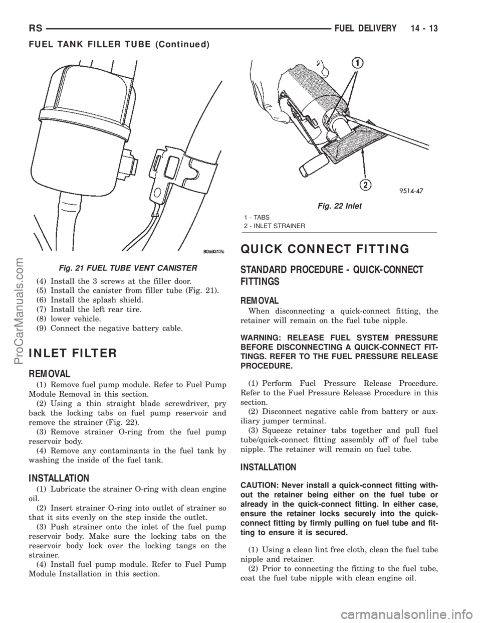
(5) Install the canister from filler tube (Fig. 21).
(6) Install the splash shield.
(7) Install the left rear tire.
(8) lower vehicle.
(9) Connect the negative battery cable.
INLET FILTER
REMOVAL
(1) Remove fuel pump module. Refer to Fuel Pump
Module Removal in this section.
(2) Using a thin straight blade screwdriver, pry
back the locking tabs on fuel pump reservoir and
remove the strainer (Fig. 22).
(3) Remove strainer O-ring from the fuel pump
reservoir body.
(4) Remove any contaminants in the fuel tank by
washing the inside of the fuel tank.
INSTALLATION
(1) Lubricate the strainer O-ring with clean engine
oil.
(2) Insert strainer O-ring into outlet of strainer so
that it sits evenly on the step inside the outlet.
(3) Push strainer onto the inlet of the fuel pump
reservoir body. Make sure the locking tabs on the
reservoir body lock over the locking tangs on the
strainer.
(4) Install fuel pump module. Refer to Fuel Pump
Module Installation in this section.
QUICK CONNECT FITTING
STANDARD PROCEDURE - QUICK-CONNECT
FITTINGS
REMOVAL
When disconnecting a quick-connect fitting, the
retainer will remain on the fuel tube nipple.
WARNING: RELEASE FUEL SYSTEM PRESSURE
BEFORE DISCONNECTING A QUICK-CONNECT FIT-
TINGS. REFER TO THE FUEL PRESSURE RELEASE
PROCEDURE.
(1) Perform Fuel Pressure Release Procedure.
Refer to the Fuel Pressure Release Procedure in this
section.
(2) Disconnect negative cable from battery or aux-
iliary jumper terminal.
(3) Squeeze retainer tabs together and pull fuel
tube/quick-connect fitting assembly off of fuel tube
nipple. The retainer will remain on fuel tube.
INSTALLATION
CAUTION: Never install a quick-connect fitting with-
out the retainer being either on the fuel tube or
already in the quick-connect fitting. In either case,
ensure the retainer locks securely into the quick-
connect fitting by firmly pulling on fuel tube and fit-
ting to ensure it is secured.
(1) Using a clean lint free cloth, clean the fuel tube
nipple and retainer.
(2) Prior to connecting the fitting to the fuel tube,
coat the fuel tube nipple with clean engine oil.
Fig. 21 FUEL TUBE VENT CANISTER
Fig. 22 Inlet
1 - TABS
2 - INLET STRAINER
RSFUEL DELIVERY14-13
FUEL TANK FILLER TUBE (Continued)
ProCarManuals.com
Page 1465 of 2399
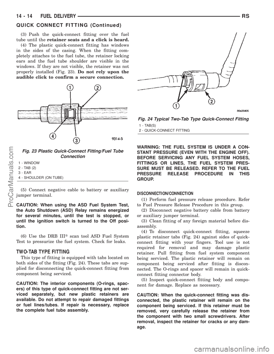
(3) Push the quick-connect fitting over the fuel
tube until theretainer seats and a click is heard.
(4) The plastic quick-connect fitting has windows
in the sides of the casing. When the fitting com-
pletely attaches to the fuel tube, the retainer locking
ears and the fuel tube shoulder are visible in the
windows. If they are not visible, the retainer was not
properly installed (Fig. 23).Do not rely upon the
audible click to confirm a secure connection.
(5) Connect negative cable to battery or auxiliary
jumper terminal.
CAUTION: When using the ASD Fuel System Test,
the Auto Shutdown (ASD) Relay remains energized
for several minutes, until the test is stopped, or
until the ignition switch is turned to the Off posi-
tion.
(6) Use the DRB IIItscan tool ASD Fuel System
Test to pressurize the fuel system. Check for leaks.
TWO-TAB TYPE FITTING
This type of fitting is equipped with tabs located on
both sides of the fitting (Fig. 24). These tabs are sup-
plied for disconnecting the quick-connect fitting from
component being serviced.
CAUTION: The interior components (O-rings, spac-
ers) of this type of quick-connect fitting are not ser-
viced separately, but new plastic retainers are
available. Do not attempt to repair damaged fittings
or fuel lines/tubes. If repair is necessary, replace
the complete fuel tube assembly.WARNING: THE FUEL SYSTEM IS UNDER A CON-
STANT PRESSURE (EVEN WITH THE ENGINE OFF).
BEFORE SERVICING ANY FUEL SYSTEM HOSES,
FITTINGS OR LINES, THE FUEL SYSTEM PRES-
SURE MUST BE RELEASED. REFER TO THE FUEL
PRESSURE RELEASE PROCEDURE IN THIS
GROUP.
DISCONNECTION/CONNECTION
(1) Perform fuel pressure release procedure. Refer
to Fuel Pressure Release Procedure in this group.
(2) Disconnect negative battery cable from battery
or auxiliary jumper terminal.
(3) Clean fitting of any foreign material before dis-
assembly.
(4) To disconnect quick-connect fitting, squeeze
plastic retainer tabs (Fig. 24) against sides of quick-
connect fitting with your fingers. Tool use is not
required for removal and may damage plastic
retainer. Pull fitting from fuel system component
being serviced. The plastic retainer will remain on
component being serviced after fitting is discon-
nected. The O-rings and spacer will remain in quick-
connect fitting connector body.
(5) Inspect quick-connect fitting body and compo-
nent for damage. Replace as necessary.
CAUTION: When the quick-connect fitting was dis-
connected, the plastic retainer will remain on the
component being serviced. If this retainer must be
removed, very carefully release the retainer from
the component with two small screwdrivers. After
removal, inspect the retainer for cracks or any dam-
age.
Fig. 23 Plastic Quick-Connect Fitting/Fuel Tube
Connection
1 - WINDOW
2-TAB(2)
3 - EAR
4 - SHOULDER (ON TUBE)
Fig. 24 Typical Two-Tab Type Quick-Connect Fitting
1 - TAB(S)
2 - QUICK-CONNECT FITTING
14 - 14 FUEL DELIVERYRS
QUICK CONNECT FITTING (Continued)
ProCarManuals.com
Page 1466 of 2399

(6) Prior to connecting quick-connect fitting to
component being serviced, check condition of fitting
and component. Clean parts with a lint-free cloth.
Lubricate with clean engine oil.
(7) Insert quick-connect fitting to component being
serviced and into plastic retainer. When a connection
is made, a click will be heard.
(8) Verify a locked condition by firmly pulling on
fuel tube and fitting (15-30 lbs.).
(9) Connect negative cable to battery or auxiliary
jumper terminal.
(10) Use the DRB IIItscan tool ASD Fuel System
Test to pressurize the fuel system. Check for leaks.
PLASTIC RETAINER RING TYPE FITTING
This type of fitting can be identified by the use of a
full-round plastic retainer ring (Fig. 25) usually black
in color.CAUTION: The interior components (O-rings, spac-
ers, retainers) of this type of quick-connect fitting
are not serviced separately. Do not attempt to repair
damaged fittings or fuel lines/tubes. If repair is nec-
essary, replace the complete fuel tube assembly.
WARNING: THE FUEL SYSTEM IS UNDER A CON-
STANT PRESSURE (EVEN WITH THE ENGINE OFF).
BEFORE SERVICING ANY FUEL SYSTEM HOSES,
FITTINGS OR LINES, THE FUEL SYSTEM PRES-
SURE MUST BE RELEASED. REFER TO THE FUEL
SYSTEM PRESSURE RELEASE PROCEDURE IN
THIS GROUP.
DISCONNECTION/CONNECTION
(1) Perform fuel pressure release procedure. Refer
to Fuel Pressure Release Procedure in this section.
(2) Disconnect negative battery cable from battery
or auxiliary jumper terminal.
(3) Clean fitting of any foreign material before dis-
assembly.
(4) To release fuel system component from quick-
connect fitting, firmly push fitting towards compo-
nent being serviced while firmly pushing plastic
retainer ring into fitting (Fig. 25). With plastic ring
depressed, pull fitting from component.The plastic
retainer ring must be pressed squarely into fit-
ting body. If this retainer is cocked during
removal, it may be difficult to disconnect fit-
ting. Use an open-end wrench on shoulder of
plastic retainer ring to aid in disconnection.
(5) After disconnection, plastic retainer ring will
remain with quick-connect fitting connector body.
(6) Inspect fitting connector body, plastic retainer
ring and fuel system component for damage. Replace
as necessary.
(7) Prior to connecting quick-connect fitting to
component being serviced, check condition of fitting
and component. Clean parts with a lint-free cloth.
Lubricate with clean engine oil.
(8) Insert quick-connect fitting into component
being serviced until a click is felt.
(9) Verify a locked condition by firmly pulling on
fuel tube and fitting (15-30 lbs.).
(10) Connect negative battery cable to battery or
auxiliary jumper terminal.
(11) Use the DRB IIItscan tool ASD Fuel System
Test to pressurize the fuel system. Check for leaks.
Fig. 25 Plastic Retainer Ring Type Fitting
1 - FUEL TUBE
2 - QUICK CONNECT FITTING
3 - PUSH
4 - PLASTIC RETAINER
5 - PUSH
6 - PUSH
7 - PUSH
8 - PUSH
RSFUEL DELIVERY14-15
QUICK CONNECT FITTING (Continued)
ProCarManuals.com