fig. 78 CHRYSLER CARAVAN 2002 Service Manual
[x] Cancel search | Manufacturer: CHRYSLER, Model Year: 2002, Model line: CARAVAN, Model: CHRYSLER CARAVAN 2002Pages: 2399, PDF Size: 57.96 MB
Page 2024 of 2399

(5) Disconnect rear window washer hose from
spray nozzle.
(6) Support liftgate on a suitable lifting device.
(7) Remove screws attaching support cylinders to
liftgate.
(8) Remove bolts attaching liftgate hinge to roof
header (Fig. 4).
(9) With assistance, remove liftgate from vehicle.
INSTALLATION
(1) With assistance, place liftgate in position on
vehicle.
(2) Install bolts attaching liftgate hinge to roof
header. Tighten bolts to 33 N´m (24 ft. lbs.) torque.(3) Install screws attaching support cylinders to
liftgate. Tighten bolts to 28 N´m (21 ft. lbs.) torque.
(4) Remove lifting device from under liftgate.
(5) Connect liftgate wire harness into body wire
harness.
(6) Install screws attaching wire connector to rear
header.
(7) Connect rear window washer hose onto spray
nozzle.
(8) Install liftgate upper frame molding.
(9) Verify liftgate alignment. The liftgate should
have a gap to adjacent panels and fit flush across the
gaps. The gap is;
²7 mm (0.280 in.) to the fascia,
²6 mm (0.240 in.) to the roof,
²4 mm (0.160 in.) to the aperture.
LIFTGATE SPOILER
REMOVAL
(1) Remove nuts (Fig. 5).
(2) Remove spoiler from vehicle.
INSTALLATION
(1) Place liftgate spoiler in position and install
nuts.
(2) Tighten nuts to 9 N´m (80 in. lbs.) torque.
Fig. 3 LIFTGATE LATCH STRIKER
1 - LIFTGATE SILL
2 - LIFTGATE STRIKER
Fig. 4 LIFTGATE
1 - HINGE
2 - ROOF
3 - NET HOLE OR SLOT
Fig. 5 LIFTGATE SPOILER
1 - RETAINER SEALER WASHER
2 - LIFT GATE SPOILER
RSDECKLID/HATCH/LIFTGATE/TAILGATE23-41
LIFTGATE (Continued)
ProCarManuals.com
Page 2025 of 2399

LOCK CYLINDER
REMOVAL
(1) Remove the liftgate trim panel. (Refer to 23 -
BODY/DECKLID/HATCH/LIFTGATE/TAILGATE/
TRIM PANEL - REMOVAL)
(2) Disconnect the electrical connector.
(3) Disconnect the latch rod.
(4) Rotate plastic lock cylinder nut one quarter
turn and remove nut and spring washer.
(5) Remove the lock cylinder from the liftgate.
INSTALLATION
(1) Install lock cylinder into liftgate.
(2) Install the plastic lock cylinder lock nut, spring
washer and rotate one quarter turn.
(3) Connect the electrical connector.
(4) Connect the latch rod.
(5) Install the trim panel. (Refer to 23 - BODY/
DECKLID/HATCH/LIFTGATE/TAILGATE/TRIM
PANEL - INSTALLATION)
(6) Verify lock cylinder operation.
SUPPORT CYLINDER
REMOVAL
(1) Release liftgate latch and open liftgate.
(2) Support liftgate on a suitable lifting device in
the full open position.
(3) Pull liftgate opening weatherstrip from D-pillar
flange next to prop assembly end pivot.
(4) Remove bolt attaching end pivot to D-pillar
(Fig. 6).
(5) Remove bolt attaching prop assembly to lift-
gate.
(6) Remove prop assembly from vehicle.
INSTALLATION
Ensure that the cylinder end is attached to the
D-pillar and the shaft end is attached to the liftgate.
(1) Place prop assembly in position.
(2) Install bolt attaching prop assembly to liftgate.
(3) Install bolt attaching end pivot to D-pillar.
Tighten bolts to 28 N´m (21 ft. lbs.) torque.
(4) Install liftgate opening weatherstrip to D-pillar
flange next to prop assembly end pivot.
(5) Close liftgate. Check liftgate operation.
TRIM PANEL
REMOVAL
(1) Remove the bolt attaching the lift motor link, if
equipped (Fig. 7).
(2) Remove liftgate upper frame molding (Fig. 8).
(3) Remove assist handle screws.
(4) Disengage hidden clips holding trim panel to
liftgate from around perimeter or liftgate (Fig. 8).
(5) Disconnect wire connector from lamps.
(6) Remove liftgate trim panel from vehicle.
Fig. 6 LIFTGATE PROP ASSEMBLY
1 - LIFTGATE
2 - PROP ASSEMBLY
Fig. 7 LIFTGATE MOTOR
1 - LIFTGATE MOTOR LINK BOLT
2 - LIFTGATE MOTOR
3 - LIFTGATE
23 - 42 DECKLID/HATCH/LIFTGATE/TAILGATERS
ProCarManuals.com
Page 2026 of 2399

INSTALLATION
(1) Place liftgate trim panel in position on vehicle.
(2) Engage hidden clips to hold trim panel to lift-
gate and fasteners around perimeter of liftgate (Fig.
8).
(3) Connect wire connector into lamp.
(4) Install courtesy lamps into liftgate trim.
(5) Install screws to hold assist handle to liftgate.
(6) Install upper frame side moldings.
(7) Install liftgate upper frame molding.
(8) Install the bolt attaching the lifgate motor link
and tighten to 28 N´m (21 ft. lbs.)
SLAM BUMPER
REMOVAL
REMOVAL
(1) Open liftgate.
(2) Remove liftgate stop bumper body side attach-
ing bolts (Fig. 9).
(3) Remove liftgate stop bumper.
REMOVAL - LIFTGATE SIDE
(1) Open liftgate.
(2) Remove liftgate stop bumper liftgate side
attaching bolts (Fig. 10).
(3) Remove liftgate stop bumper.
INSTALLATION
INSTALLATION
(1) Place liftgate stop bumper into position.
(2) Install bolts attaching liftgate stop bumper to
body side (Fig. 9).
(3) Close liftgate.
INSTALLATION - LIFTGATE SIDE
(1) Place liftgate stop bumper into position.
(2) Install bolts attaching liftgate stop bumper to
liftgate (Fig. 10).
(3) Close liftgate.
Fig. 8 LIFTGATE TRIM
1 - LIFTGATE
2 - LOWER TRIM PANEL
3 - ASSIST HANDLE SCREWS
4 - UPPER TRIM
5 - UPPER TRIM CLIPS
Fig. 9 LIFTGATE STOP BUMPER - BODY SIDE
1 - LIFTGATE STOP BUMPER
2 - LIFTGATE OPENING
Fig. 10 LIFTGATE STOP BUMPER - LIFTGATE SIDE
1 - LIFTGATE STOP BUMPER
2 - LIFTGATE
RSDECKLID/HATCH/LIFTGATE/TAILGATE23-43
TRIM PANEL (Continued)
ProCarManuals.com
Page 2027 of 2399

EXTERIOR
TABLE OF CONTENTS
page page
BODY SIDE MOLDINGS
REMOVAL.............................44
INSTALLATION.........................45
COWL GRILLE
REMOVAL.............................50
INSTALLATION.........................50
EXTERIOR NAME PLATES - TAPE ATTACHED
REMOVAL.............................50
INSTALLATION.........................51
EXTERIOR NAME PLATES - ADHESIVE
ATTACHED
REMOVAL.............................51
INSTALLATION.........................51
FRONT FENDER
REMOVAL.............................51
INSTALLATION.........................51
FUEL FILL DOOR
REMOVAL.............................52
INSTALLATION.........................52
FUEL FILL DOOR BLOCKER LATCH
REMOVAL.............................52
INSTALLATION.........................52
FUEL FILL DOOR BLOCKER LATCH STRIKER
REMOVAL.............................53
INSTALLATION.........................53
FUEL FILL DOOR BLOCKER LOCKOUT LINK
REMOVAL.............................53INSTALLATION.........................54
GRILLE OPENING REINFORCEMENT
REMOVAL.............................54
INSTALLATION.........................54
FRONT WHEELHOUSE SPLASH SHIELD
REMOVAL.............................55
INSTALLATION.........................55
LUGGAGE RACK RISER
REMOVAL.............................55
INSTALLATION.........................56
LUGGAGE RACK CROSSBAR
REMOVAL.............................56
INSTALLATION.........................57
REAR QUARTER PANEL/FENDER AIR
EXHAUSTER
DESCRIPTION.........................57
REMOVAL.............................57
INSTALLATION.........................58
ROOF JOINT MOLDING
REMOVAL.............................58
INSTALLATION.........................58
SIDE VIEW MIRROR
REMOVAL.............................58
INSTALLATION.........................58
SIDE VIEW MIRROR GLASS
REMOVAL.............................59
INSTALLATION.........................59
BODY SIDE MOLDINGS
REMOVAL
Refer to (Fig. 1), (Fig. 2), (Fig. 3), (Fig. 4) or (Fig.
5)for proper location of fasteners holding the molding
to the wheelhouse lip and rocker panels.
(1) Warm the affected stick on molding and body
metal to approximately 38É C (100É F) using a suit-
able heat lamp or heat gun.(2) If equipped, remove pop rivets holding molding
edge to wheelhouse lip.
(3) Pull stick on molding from painted surface.
(4) Remove adhesive tape residue from painted
surface of vehicle. Use a 3M Scotch-BriteŸ Molding
Adhesive and Stripe Removal Disc, or equivalent, to
clean adhesive residue from painted surfaces. These
products are available from automotive paint suppli-
ers. Refer to instructions supplied with the specific
product for proper usage.
23 - 44 EXTERIORRS
ProCarManuals.com
Page 2028 of 2399
INSTALLATION
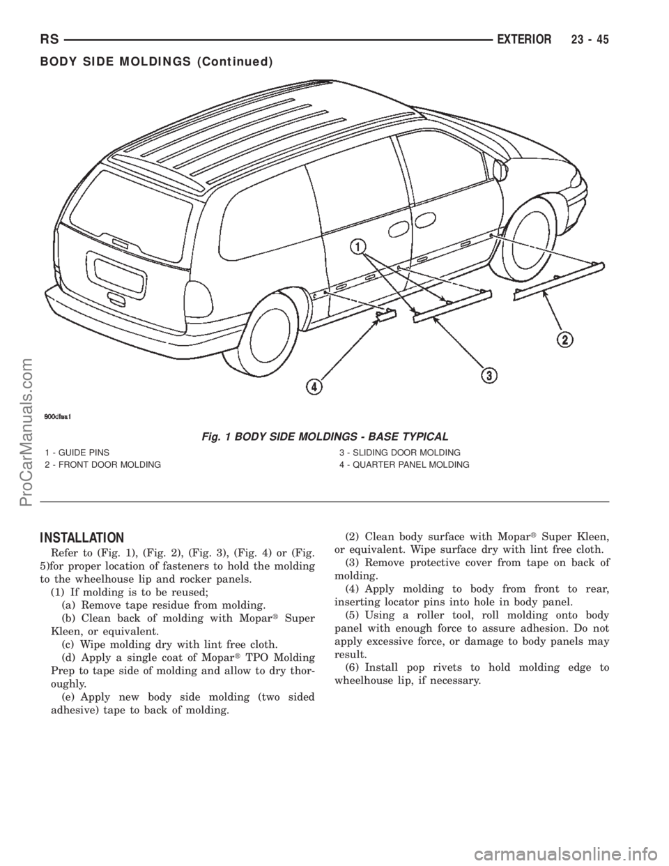
Refer to (Fig. 1), (Fig. 2), (Fig. 3), (Fig. 4) or (Fig.
5)for proper location of fasteners to hold the molding
to the wheelhouse lip and rocker panels.
(1) If molding is to be reused;
(a) Remove tape residue from molding.
(b) Clean back of molding with MopartSuper
Kleen, or equivalent.
(c) Wipe molding dry with lint free cloth.
(d) Apply a single coat of MopartTPO Molding
Prep to tape side of molding and allow to dry thor-
oughly.
(e) Apply new body side molding (two sided
adhesive) tape to back of molding.(2) Clean body surface with MopartSuper Kleen,
or equivalent. Wipe surface dry with lint free cloth.
(3) Remove protective cover from tape on back of
molding.
(4) Apply molding to body from front to rear,
inserting locator pins into hole in body panel.
(5) Using a roller tool, roll molding onto body
panel with enough force to assure adhesion. Do not
apply excessive force, or damage to body panels may
result.
(6) Install pop rivets to hold molding edge to
wheelhouse lip, if necessary.
Fig. 1 BODY SIDE MOLDINGS - BASE TYPICAL
1 - GUIDE PINS
2 - FRONT DOOR MOLDING3 - SLIDING DOOR MOLDING
4 - QUARTER PANEL MOLDING
RSEXTERIOR23-45
BODY SIDE MOLDINGS (Continued)
ProCarManuals.com
Page 2029 of 2399
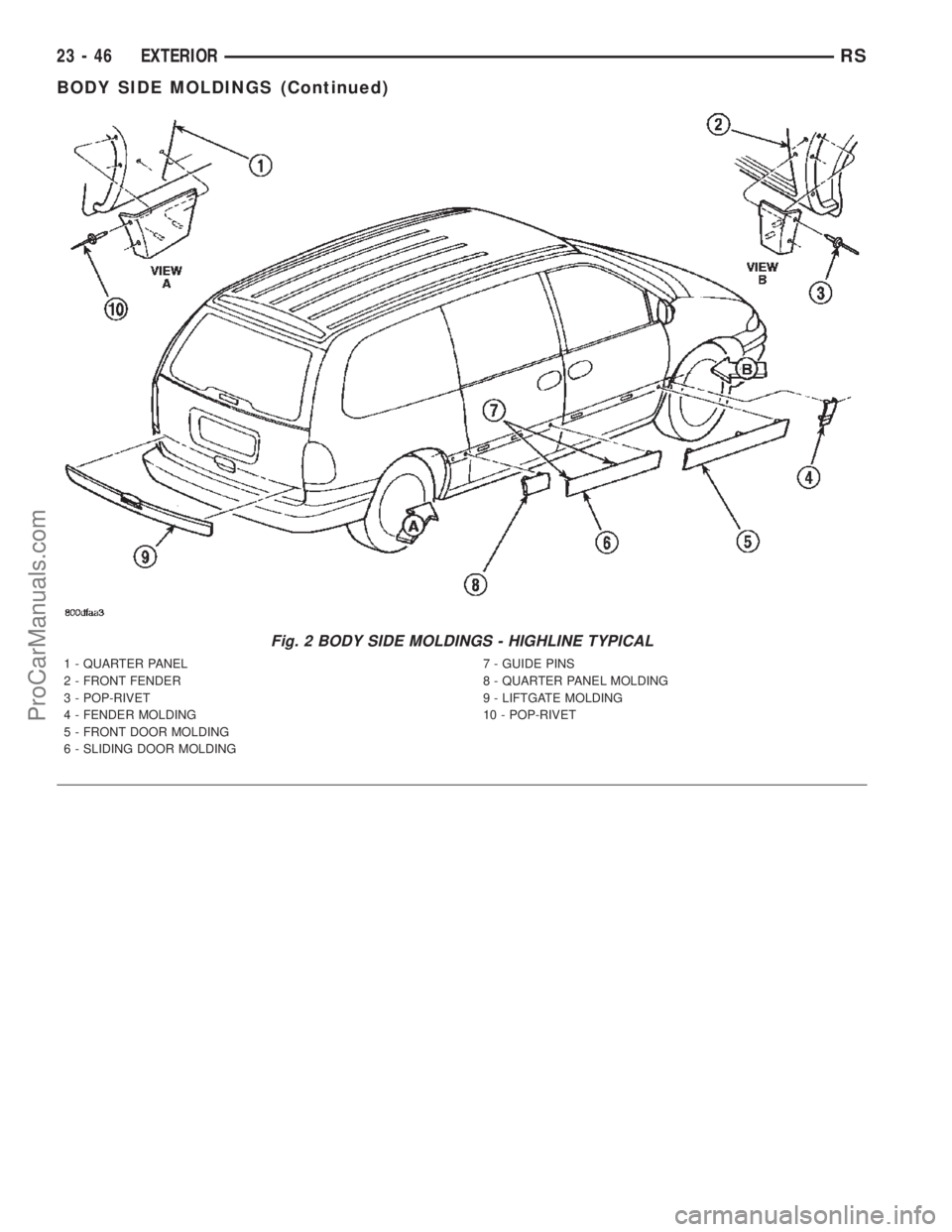
Fig. 2 BODY SIDE MOLDINGS - HIGHLINE TYPICAL
1 - QUARTER PANEL
2 - FRONT FENDER
3 - POP-RIVET
4 - FENDER MOLDING
5 - FRONT DOOR MOLDING
6 - SLIDING DOOR MOLDING7 - GUIDE PINS
8 - QUARTER PANEL MOLDING
9 - LIFTGATE MOLDING
10 - POP-RIVET
23 - 46 EXTERIORRS
BODY SIDE MOLDINGS (Continued)
ProCarManuals.com
Page 2030 of 2399
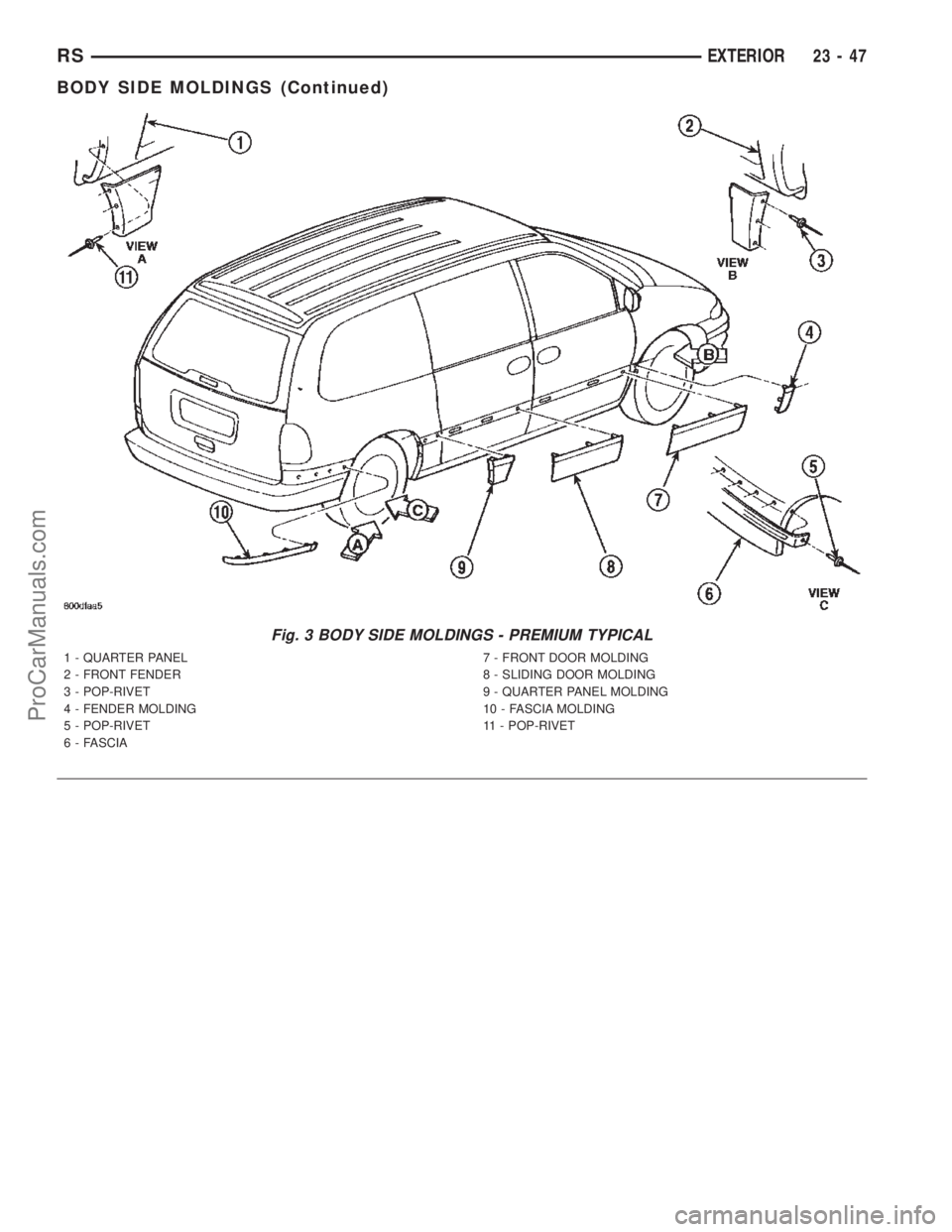
Fig. 3 BODY SIDE MOLDINGS - PREMIUM TYPICAL
1 - QUARTER PANEL
2 - FRONT FENDER
3 - POP-RIVET
4 - FENDER MOLDING
5 - POP-RIVET
6 - FASCIA7 - FRONT DOOR MOLDING
8 - SLIDING DOOR MOLDING
9 - QUARTER PANEL MOLDING
10 - FASCIA MOLDING
11 - POP-RIVET
RSEXTERIOR23-47
BODY SIDE MOLDINGS (Continued)
ProCarManuals.com
Page 2031 of 2399
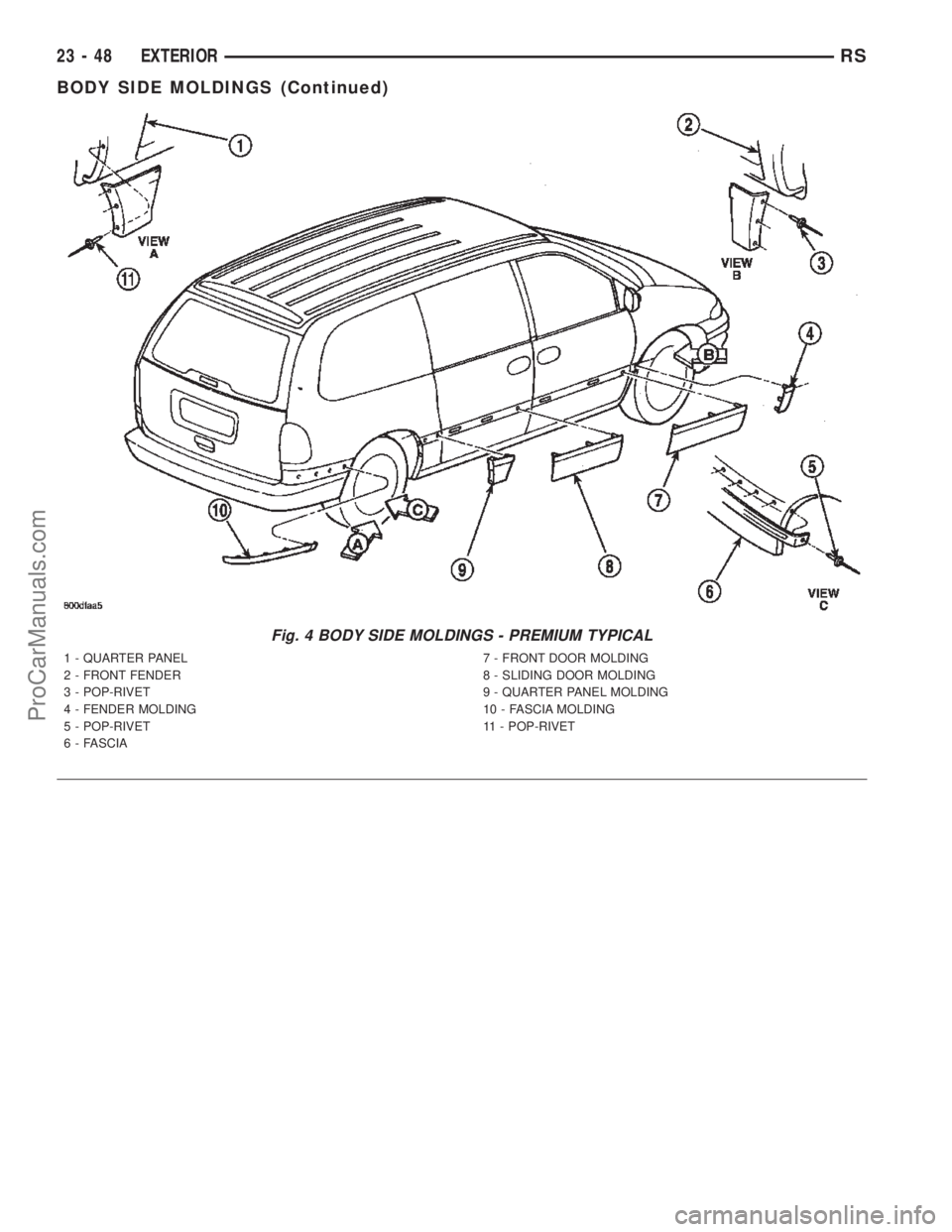
Fig. 4 BODY SIDE MOLDINGS - PREMIUM TYPICAL
1 - QUARTER PANEL
2 - FRONT FENDER
3 - POP-RIVET
4 - FENDER MOLDING
5 - POP-RIVET
6 - FASCIA7 - FRONT DOOR MOLDING
8 - SLIDING DOOR MOLDING
9 - QUARTER PANEL MOLDING
10 - FASCIA MOLDING
11 - POP-RIVET
23 - 48 EXTERIORRS
BODY SIDE MOLDINGS (Continued)
ProCarManuals.com
Page 2032 of 2399
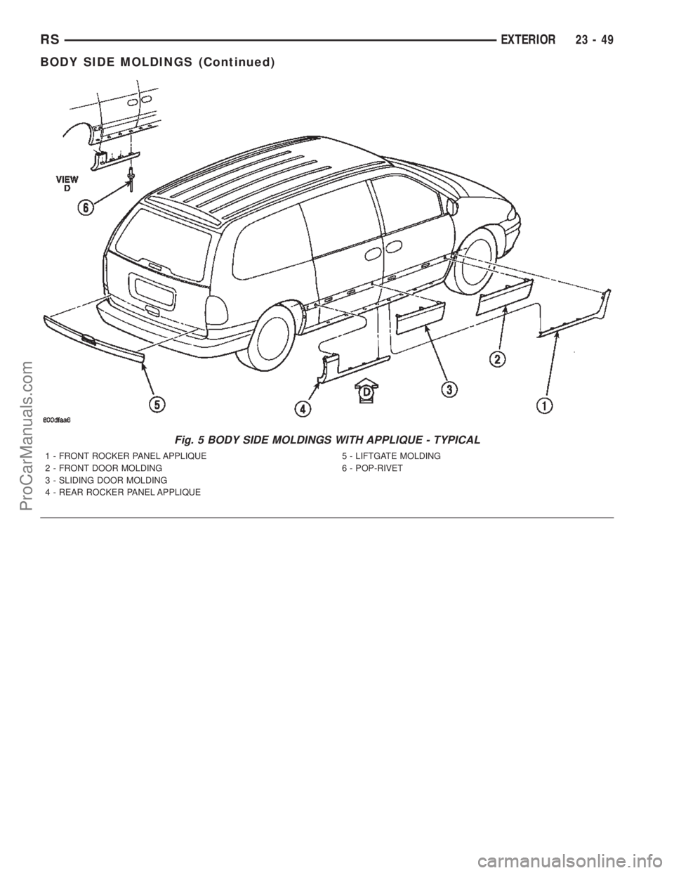
Fig. 5 BODY SIDE MOLDINGS WITH APPLIQUE - TYPICAL
1 - FRONT ROCKER PANEL APPLIQUE
2 - FRONT DOOR MOLDING
3 - SLIDING DOOR MOLDING
4 - REAR ROCKER PANEL APPLIQUE5 - LIFTGATE MOLDING
6 - POP-RIVET
RSEXTERIOR23-49
BODY SIDE MOLDINGS (Continued)
ProCarManuals.com
Page 2033 of 2399

COWL GRILLE
REMOVAL
(1) Remove wiper arms. (Refer to 8 - ELECTRI-
CAL/WIPERS/WASHERS/WIPER ARMS -
REMOVAL)
(2) Remove four (4) screws securing cowl cover to
wiper module (Fig. 6).
(3) Disengage quarter turn fasteners at outboard
ends of cowl grill from body.
(4) Release hood latch and open hood.
CAUTION: To prevent hood scratching of cowl grille
before removal, cover outboard exterior ends of
cowl grille with masking tape or equivalent method.
NOTE: Do not over bend cowl grille during removal.
Bend cowl grille just enough to clear top of wiper
pivot shaft and bottom rear corner of hood.
(5) Remove cowl grill by raising above driver side
wiper pivot shaft and swinging away towards engine
compartment. The cowl grille will need to be bent on
outboard end to clear simultaneously top of wiper
pivot shaft and bottom corner of hood.
(6) Close hood. Do not latch. Remove outboard
screws. (Fig. 7).
(7) Disconnect washer hose in line connector.
(8) Disconnect washer hose and grommet from
hole in wiper module and pull out.
(9) Remove cowl grille by raising over opposite
wiper pivot shaft and removing away from vehicle.
(10) Remove cowl cover from vehicle.
INSTALLATION
(1) Reverse removal procedure.
(2) When installing cowl cover over wiper module,
make sure fore aft locator on the underside of cowl
grill seat into the locator grooves on top of wiper
module.
(3) Star all cowl grille mounting screws by hand
before torquing to specifications.
(4) Assure washer hose is properly routed and not
pinched.
(5) Center cowl grille to body and windshield.
(6) Assure ªarrowº indicator head of quarter turn
fasteners is pointing toward windshield.
(7) Tighten screw to 1.2 N´m (11 in. lbs.) torque.
(8) Install the wiper arms. (Refer to 8 - ELECTRI-
CAL/WIPERS/WASHERS/WIPER ARMS - INSTAL-
LATION)
(9) Check for proper spray pattern from washer
nozzles.
EXTERIOR NAME PLATES -
TAPE ATTACHED
REMOVAL
(1) Mark reference points before removing.
(2) Using a heat gun gently apply heat in a circu-
lar motion to loosen the adhesive bond.
(3) Using a nonmetallic prying device, such as a
plastic or wood trim stick gently pry up at corners
and remove.Fig. 6 COWL COVER
1 - COWL COVER
2 - WIPER PIVOT
3 - WASHER HOSES
4 - HOOD
Fig. 7 COWL COVER RETAINERS
1 - SCREW
2 - WINDSHIELD
3 - COWL COVER
4 - FRONT FENDER
23 - 50 EXTERIORRS
ProCarManuals.com