fig. 78 CHRYSLER CARAVAN 2002 Service Manual
[x] Cancel search | Manufacturer: CHRYSLER, Model Year: 2002, Model line: CARAVAN, Model: CHRYSLER CARAVAN 2002Pages: 2399, PDF Size: 57.96 MB
Page 2376 of 2399
PCV VALVE
DESCRIPTION
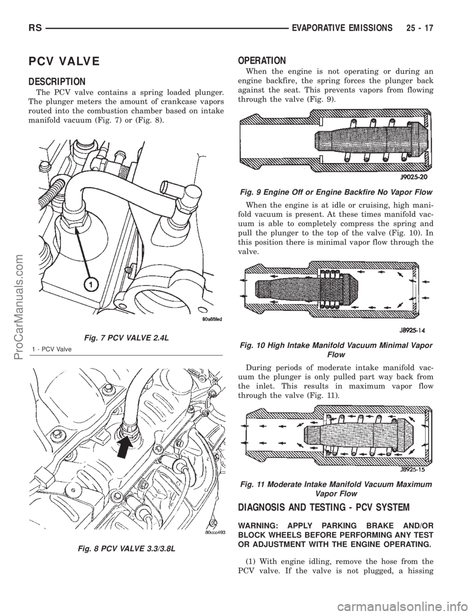
The PCV valve contains a spring loaded plunger.
The plunger meters the amount of crankcase vapors
routed into the combustion chamber based on intake
manifold vacuum (Fig. 7) or (Fig. 8).
OPERATION
When the engine is not operating or during an
engine backfire, the spring forces the plunger back
against the seat. This prevents vapors from flowing
through the valve (Fig. 9).
When the engine is at idle or cruising, high mani-
fold vacuum is present. At these times manifold vac-
uum is able to completely compress the spring and
pull the plunger to the top of the valve (Fig. 10). In
this position there is minimal vapor flow through the
valve.
During periods of moderate intake manifold vac-
uum the plunger is only pulled part way back from
the inlet. This results in maximum vapor flow
through the valve (Fig. 11).
DIAGNOSIS AND TESTING - PCV SYSTEM
WARNING: APPLY PARKING BRAKE AND/OR
BLOCK WHEELS BEFORE PERFORMING ANY TEST
OR ADJUSTMENT WITH THE ENGINE OPERATING.
(1) With engine idling, remove the hose from the
PCV valve. If the valve is not plugged, a hissing
Fig. 7 PCV VALVE 2.4L
1 - PCV Valve
Fig. 8 PCV VALVE 3.3/3.8L
Fig. 9 Engine Off or Engine Backfire No Vapor Flow
Fig. 10 High Intake Manifold Vacuum Minimal Vapor
Flow
Fig. 11 Moderate Intake Manifold Vacuum Maximum
Vapor Flow
RSEVAPORATIVE EMISSIONS25-17
ProCarManuals.com
Page 2377 of 2399
noise will be heard as air passes through the valve. A
strong vacuum should also be felt when a finger is
placed over the valve inlet.
(2) Install hose on PCV valve. Remove the
make-up air hose from the air plenum at the rear of
the engine. Hold a piece of stiff paper (parts tag)
loosely over the end of the make-up air hose.
(3) After allowing approximately one minute for
crankcase pressure to reduce, the paper should draw
up against the hose with noticeable force. If the
engine does not draw the paper against the grommet
after installing a new valve, replace the PCV valve
hose.
(4) Turn the engine off. Remove the PCV valve
from intake manifold. The valve should rattle when
shaken.
(5) Replace the PCV valve and retest the system if
it does not operate as described in the preceding
tests.Do not attempt to clean the old PCV valve.
If the valve rattles, apply a light coating of Loctitet
Pipe Sealant With Teflon to the threads. Thread the
PCV valve into the manifold plenum and tighten to 7
N´m (60 in. lbs.) torque.
VAPOR CANISTER
DESCRIPTION
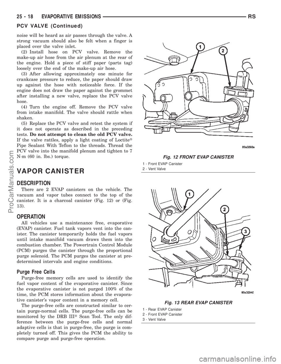
There are 2 EVAP canisters on the vehicle. The
vacuum and vapor tubes connect to the top of the
canister. It is a charcoal canister (Fig. 12) or (Fig.
13).
OPERATION
All vehicles use a maintenance free, evaporative
(EVAP) canister. Fuel tank vapors vent into the can-
ister. The canister temporarily holds the fuel vapors
until intake manifold vacuum draws them into the
combustion chamber. The Powertrain Control Module
(PCM) purges the canister through the proportional
purge solenoid. The PCM purges the canister at pre-
determined intervals and engine conditions.
Purge Free Cells
Purge-free memory cells are used to identify the
fuel vapor content of the evaporative canister. Since
the evaporative canister is not purged 100% of the
time, the PCM stores information about the evapora-
tive canister's vapor content in a memory cell.
The purge-free cells are constructed similar to cer-
tain purge-normal cells. The purge-free cells can be
monitored by the DRB IIItScan Tool. The only dif-
ference between the purge-free cells and normal
adaptive cells is that in purge-free, the purge is com-
pletely turned off. This gives the PCM the ability to
compare purge and purge-free operation.
Fig. 12 FRONT EVAP CANISTER
1 - Front EVAP Canister
2 - Vent Valve
Fig. 13 REAR EVAP CANISTER
1 - Rear EVAP Canister
2 - Front EVAP Canister
3 - Vent Valve
25 - 18 EVAPORATIVE EMISSIONSRS
PCV VALVE (Continued)
ProCarManuals.com
Page 2378 of 2399
REMOVAL
REMOVAL
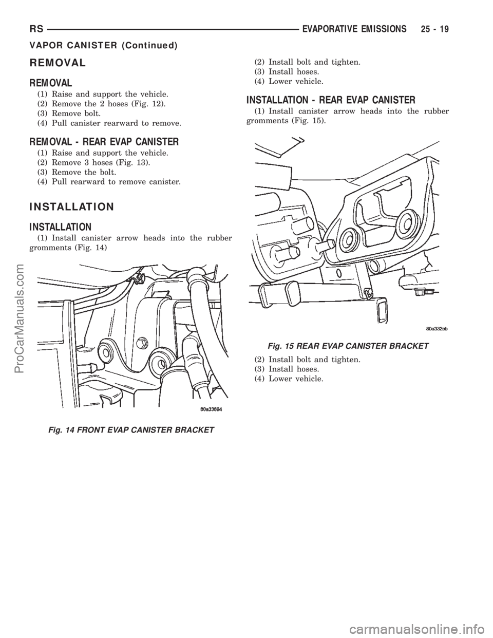
(1) Raise and support the vehicle.
(2) Remove the 2 hoses (Fig. 12).
(3) Remove bolt.
(4) Pull canister rearward to remove.
REMOVAL - REAR EVAP CANISTER
(1) Raise and support the vehicle.
(2) Remove 3 hoses (Fig. 13).
(3) Remove the bolt.
(4) Pull rearward to remove canister.
INSTALLATION
INSTALLATION
(1) Install canister arrow heads into the rubber
gromments (Fig. 14)(2) Install bolt and tighten.
(3) Install hoses.
(4) Lower vehicle.
INSTALLATION - REAR EVAP CANISTER
(1) Install canister arrow heads into the rubber
gromments (Fig. 15).
(2) Install bolt and tighten.
(3) Install hoses.
(4) Lower vehicle.
Fig. 14 FRONT EVAP CANISTER BRACKET
Fig. 15 REAR EVAP CANISTER BRACKET
RSEVAPORATIVE EMISSIONS25-19
VAPOR CANISTER (Continued)
ProCarManuals.com
Page 2380 of 2399
(2) Disconnect the fresh air makeup hose on rear
valve cover.
(3) Remove the air box bolt.
(4) Remove the hose clamp at throttle body.
(5) Unlatch 2 clamps for air box cover.
(6) Remove air box cover.
(7) Disconnect the washer fluid fill hose.
(8) Remove air box.
(9) Remove the 2 bolts at the EGR valve.
(10) Remove the 2 bolts at the intake manifold.
(11) Remove front EGR tube.
REMOVAL - REAR TUBE - 3.5L
(1) Remove the battery, refer to the Battery sec-
tion.
(2) Remove the Battery tray/vacuum reservoir.
(3) Remove the speed control servo and bracket
and relocate.
(4) Remove the 2 bolts from the EGR valve.
(5) Remove the 2 bolts from the rear cylinder
head.
(6) Remove the EGR rear tube.
INSTALLATION
INSTALLATION - 2.4L
(1) Loose install EGR tube and gasket with attach-
ing bolts at intake manifold.
(2) Loose install EGR tube and gasket with attach-
ing bolts at EGR valve.
(3) Tighten bolts to EGR valve to 11.9 N´m (105
20 ins. lbs.).
(4) Tighten bolts to Intake manifold to 11.9 N´m
(105 20 ins. lbs.).
INSTALLATION - FRONT TUBE - 3.5L
(1) Install front EGR tube and gaskets.
(2) Install the 2 bolts at the EGR valve.
(3) Install the 2 bolts at the intake manifold.
(4) Tighten all 4 bolts.
(5) Install air box.
(6) Connect the washer fluid fill hose.
(7) Install air box cover.
(8) Latch 2 clamps for air box cover.
(9) Install the hose clamp at throttle body.
(10) Install the air box bolt.
(11) Connect the fresh air makeup hose on rear
valve cover.
(12) Connect the negative battery cable.
INSTALLATION - REAR TUBE - 3.5L
(1) Install the EGR rear tube.
(2) Install the 2 bolts to the rear cylinder head.
(3) Install the 2 bolts to the EGR valve.
(4) Tighten the 4 bolts.(5) Install the speed control servo and bracket,
refer to the speed control section.
(6) Install the Battery tray/vacuum reservoir refer
to the battery section.
(7) Install the battery, refer to the Battery section.
VA LV E
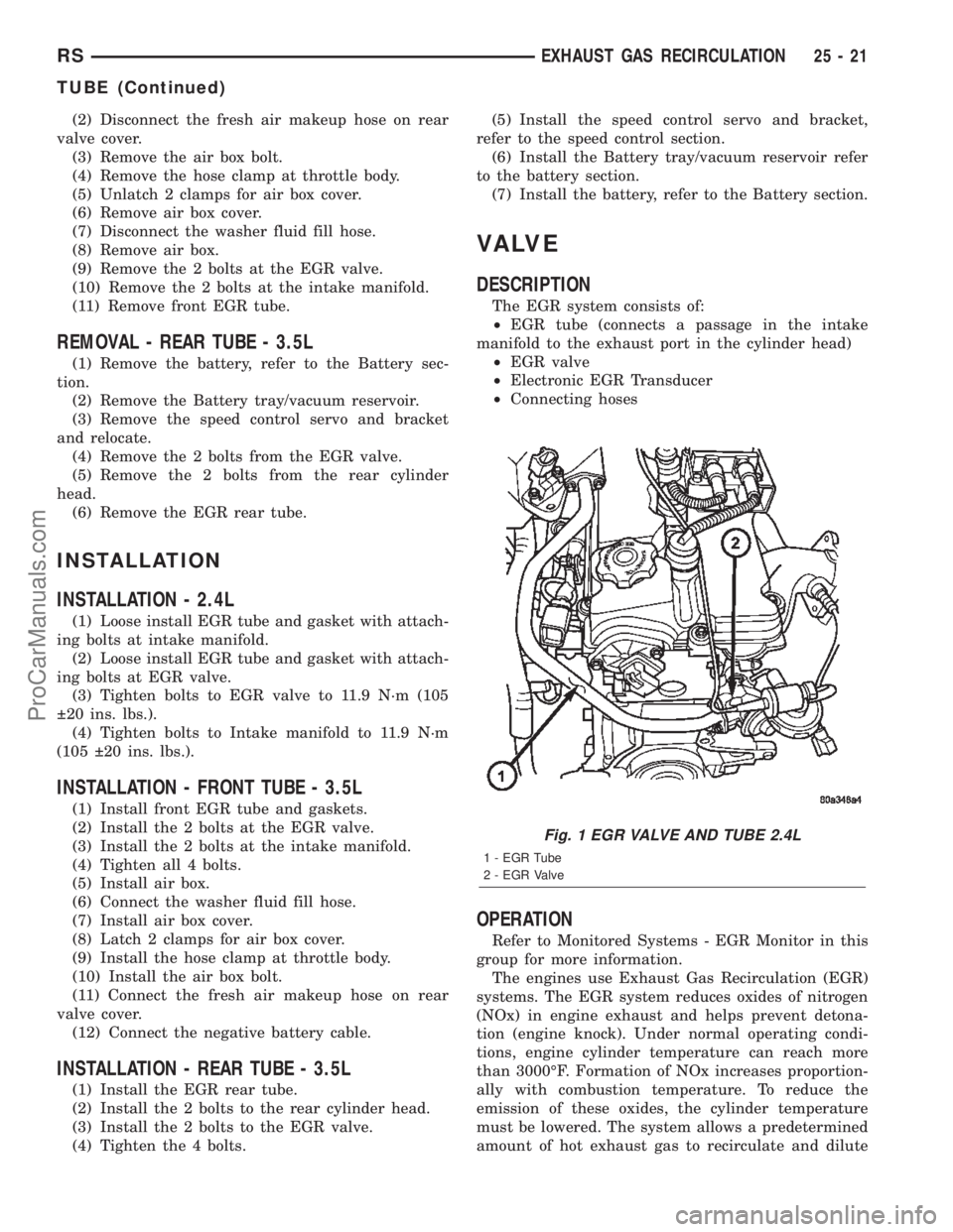
DESCRIPTION
The EGR system consists of:
²EGR tube (connects a passage in the intake
manifold to the exhaust port in the cylinder head)
²EGR valve
²Electronic EGR Transducer
²Connecting hoses
OPERATION
Refer to Monitored Systems - EGR Monitor in this
group for more information.
The engines use Exhaust Gas Recirculation (EGR)
systems. The EGR system reduces oxides of nitrogen
(NOx) in engine exhaust and helps prevent detona-
tion (engine knock). Under normal operating condi-
tions, engine cylinder temperature can reach more
than 3000ÉF. Formation of NOx increases proportion-
ally with combustion temperature. To reduce the
emission of these oxides, the cylinder temperature
must be lowered. The system allows a predetermined
amount of hot exhaust gas to recirculate and dilute
Fig. 1 EGR VALVE AND TUBE 2.4L
1 - EGR Tube
2 - EGR Valve
RSEXHAUST GAS RECIRCULATION25-21
TUBE (Continued)
ProCarManuals.com
Page 2381 of 2399
the incoming air/fuel mixture. The diluted air/fuel
mixture reduces peak flame temperature during com-
bustion.
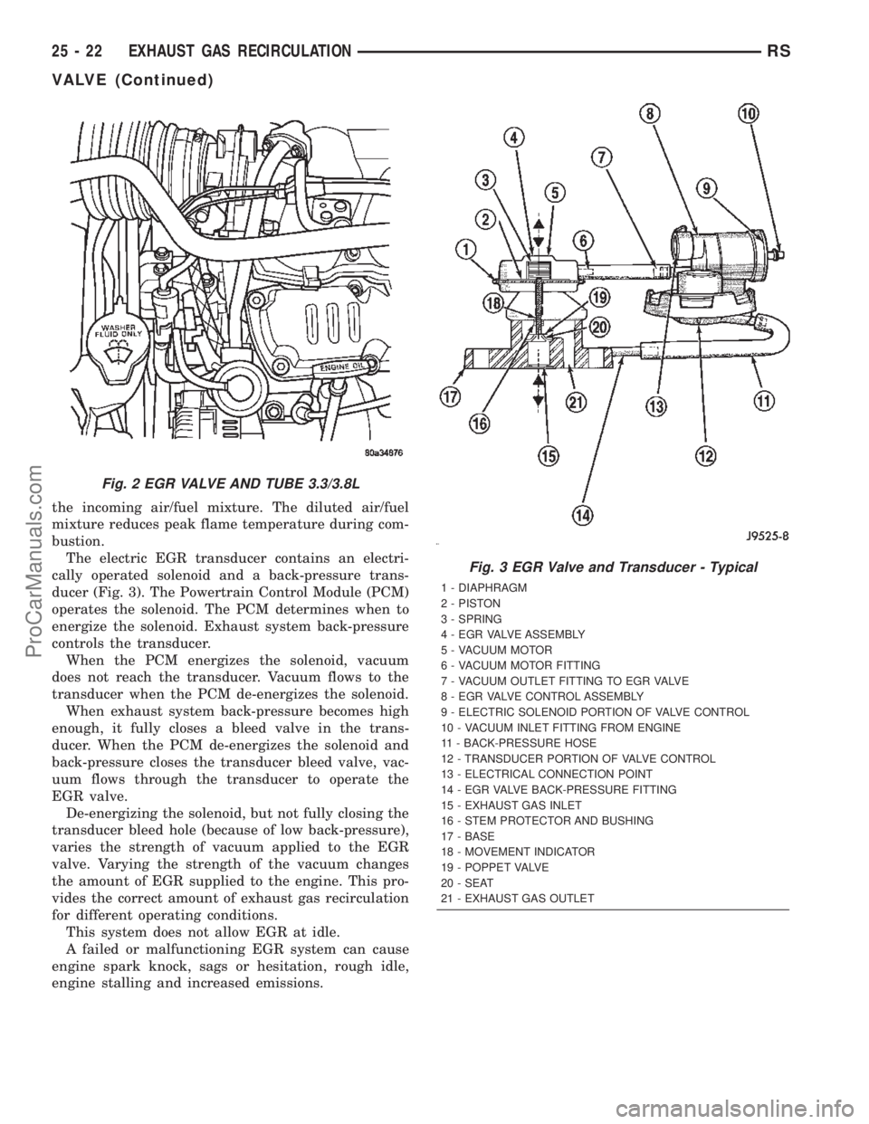
The electric EGR transducer contains an electri-
cally operated solenoid and a back-pressure trans-
ducer (Fig. 3). The Powertrain Control Module (PCM)
operates the solenoid. The PCM determines when to
energize the solenoid. Exhaust system back-pressure
controls the transducer.
When the PCM energizes the solenoid, vacuum
does not reach the transducer. Vacuum flows to the
transducer when the PCM de-energizes the solenoid.
When exhaust system back-pressure becomes high
enough, it fully closes a bleed valve in the trans-
ducer. When the PCM de-energizes the solenoid and
back-pressure closes the transducer bleed valve, vac-
uum flows through the transducer to operate the
EGR valve.
De-energizing the solenoid, but not fully closing the
transducer bleed hole (because of low back-pressure),
varies the strength of vacuum applied to the EGR
valve. Varying the strength of the vacuum changes
the amount of EGR supplied to the engine. This pro-
vides the correct amount of exhaust gas recirculation
for different operating conditions.
This system does not allow EGR at idle.
A failed or malfunctioning EGR system can cause
engine spark knock, sags or hesitation, rough idle,
engine stalling and increased emissions.
Fig. 2 EGR VALVE AND TUBE 3.3/3.8L
Fig. 3 EGR Valve and Transducer - Typical
1 - DIAPHRAGM
2 - PISTON
3 - SPRING
4 - EGR VALVE ASSEMBLY
5 - VACUUM MOTOR
6 - VACUUM MOTOR FITTING
7 - VACUUM OUTLET FITTING TO EGR VALVE
8 - EGR VALVE CONTROL ASSEMBLY
9 - ELECTRIC SOLENOID PORTION OF VALVE CONTROL
10 - VACUUM INLET FITTING FROM ENGINE
11 - BACK-PRESSURE HOSE
12 - TRANSDUCER PORTION OF VALVE CONTROL
13 - ELECTRICAL CONNECTION POINT
14 - EGR VALVE BACK-PRESSURE FITTING
15 - EXHAUST GAS INLET
16 - STEM PROTECTOR AND BUSHING
17 - BASE
18 - MOVEMENT INDICATOR
19 - POPPET VALVE
20 - SEAT
21 - EXHAUST GAS OUTLET
25 - 22 EXHAUST GAS RECIRCULATIONRS
VALVE (Continued)
ProCarManuals.com
Page 2382 of 2399
REMOVAL
REMOVAL - 2.4L
The EGR valve and Electrical EGR Transducer are
serviced as an assembly (Fig. 1).
(1) Disconnect vacuum tube from electric EGR
transducer. Inspect vacuum tube for damage.
(2) Remove electrical connector from solenoid.
(3) Remove EGR tube bolts from EGR valve.
(4) Remove EGR valve from cylinder head adaptor.
(5) Clean gasket surface and discard old gasket.
Check for any signs of leakage or cracked surfaces.
Repair or replace as necessary.
REMOVAL - 3.5L
(1) Disconnect the negative battery cable.
(2) Disconnect the fresh air makeup hose on rear
valve cover.
(3) Remove the air box bolt.
(4) Remove the hose clamp at throttle body.
(5) Unlatch 2 clamps for air box cover.
(6) Remove air box cover.
(7) Unlock the electrical connector.
(8) Disconnect the electrical connector from the
EGR valve.
(9) Remove the 2 bolts for the front EGR tube
(10) Remove the 2 bolts for the rear EGR tube
(11) Remove the 2 EGR valve mounting bolts.
(12) Remove the EGR valve.
INSTALLATION
INSTALLATION - 2.4L
The EGR valve and Electrical EGR Transducer are
serviced as an assembly (Fig. 1).
(1) Assemble EGR valve with new gasket onto the
cylinder head adaptor.
(2) Loose assemble the bolts from EGR valve to
EGR tube.
(3) Loose assemble the bolts from EGR valve to
cylinder head.
(4) Tighten bolts from EGR valve to cylinder head
to 22.8 N´m (200 25 in. lbs.) torque.
(5) Tighten bolts from EGR valve to EGR tube to
11.9 N´m (105 20 in. lbs.) torque.
(6) Reconnect vacuum hose and electrical connec-
tor to electrical EGR transducer.
INSTALLATION - 3.5L
(1) Install the EGR valve.
(2) Install the 2 bolts for the rear EGR tube
(3) Install the 2 bolts for the front EGR tube
(4) Tighten the EGR tube bolts.
(5) Tighten the EGR valve mounting bolts.
(6) Connect the electrical connector to the EGR
valve.
(7) Lock the electrical connector.
(8) Install air box cover.
(9) Latch 2 clamps for air box cover.
(10) Install the hose clamp at throttle body.
(11) Connect the fresh air makeup hose on rear
valve cover.
(12) Connect the negative battery cable.
RSEXHAUST GAS RECIRCULATION25-23
VALVE (Continued)
ProCarManuals.com
Page 2391 of 2399

VA LV E
DESCRIPTION
The EGR system consists of (Fig. 1):
²EGR valve
²EGR tube
²Vacuum hoses
²EGR cooler
²EGR solenoid
OPERATION
The engines use Exhaust Gas Recirculation (EGR)
systems. The EGR system reduces oxides of nitrogen
(NOx) in engine exhaust and helps prevent detona-
tion (engine knock). Under normal operating condi-
tions, engine cylinder temperature can reach more
than 3000ÉF. Formation of NOx increases proportion-
ally with combustion temperature. To reduce the
emission of these oxides, the cylinder temperature
must be lowered. The system allows a predetermined
amount of hot exhaust gas to recirculate and dilute
the incoming air/fuel mixture. The diluted air/fuel
mixture reduces peak flame temperature during com-
bustion.
REMOVAL
(1) Remove engine cover (Refer to 9 - ENGINE -
REMOVAL).
(2) Remove front wiper unit (Refer to 8 - ELEC-
TRICAL/WIPERS/WASHERS/WIPER MODULE -
REMOVAL).
(3) Disconnect EGR valve vacuum line.
(4) Remove EGR cooler to EGR valve retaining
bolts (Fig. 1).
(5) Remove EGR valve retaining nuts (Fig. 1) and
EGR valve.
INSTALLATION
(1) Clean gasket mating surfaces.
(2) Install EGR valve (Fig. 1). Torque nuts to
32.4N´m.
(3) Connect EGR cooler to EGR valve (Fig. 1).
Torque bolts to 32.4N´m
(4) Install front wiper unit (Refer to 8 - ELECTRI-
CAL/WIPERS/WASHERS/WIPER MODULE -
INSTALLATION).
(5) Install engine cover (Refer to 9 - ENGINE -
INSTALLATION).
Fig. 1 EGR COMPONENTS
1 - HOSE CLAMP
2 - COOLANT HOSE
3 - HOSE CLAMP
4 - EGR VALVE RETAINING NUT
5 - E G R VA LV E
6 - COOLANT HOSE
7 - EGR VALVE GASKET
8 - EGR VALVE RETAINING STUDS
9 - EGR COOLER RETAINING BOLT
10 - HOSE CLAMP
11 - HOSE CLAMP
12 - EGR COOLER
13 - EGR COOLER TO EGR VALVE RETAINING BOLT
14 - TURBOCHARGER BRACKET
15 - TURBOCHARGER BRACKET RETAINING BOLT
16 - TURBOCHARGER DOWNPIPE
17 - TURBOCHARGER DOWNPIPE RETAINING NUT
18 - DOWNPIPE GASKET
19 - DOWNPIPE STUD
25a - 4 EXHAUST GAS RECIRCULATIONRG
ProCarManuals.com
Page 2392 of 2399

VALVE COOLER
DESCRIPTION
The EGR valve on this engine uses a cooler to cool
the exhaust gases before the returned to the intake
manifold (Fig. 2). The EGR cooler attaches to the
EGR valve and is cooled with engine coolant.
REMOVAL
(1) Remove engine cover (Refer to 9 - ENGINE -
REMOVAL).
(2) Partially drain cooling system (Refer to 7 -
COOLING/ENGINE/COOLANT - STANDARD PRO-
CEDURE).
(3) Remove front wiper unit (Refer to 8 - ELEC-
TRICAL/WIPERS/WASHERS/WIPER MODULE -
REMOVAL).
(4) Disconnect coolant supply and return lines at
EGR cooler (Fig. 2).
(5) Remove EGR cooler to exhaust manifold retain-
ing bolt (Fig. 2).
(6) Remove EGR cooler to EGR valve retaining
bolts (Fig. 2) and remove cooler.
INSTALLATION
(1) Clean gasket sealing surfaces.
(2) Connect EGR valve cooler and new gasket to
EGR valve (Fig. 2). Torque bolts to 32.4N´m.
(3) Install EGR valve cooler to exhaust manifold
attaching bolt (Fig. 2). Torque bolt to 32.4N´m.
(4) Connect EGR cooler coolant supply and return
hoses to cooler (Fig. 2).
(5) Install front wiper unit (Refer to 8 - ELECTRI-
CAL/WIPERS/WASHERS/WIPER MODULE -
INSTALLATION).
(6) Refill cooling system (Refer to 7 - COOLING/
ENGINE/COOLANT - STANDARD PROCEDURE).
(7) Install engine cover (Refer to 9 - ENGINE -
INSTALLATION).
Fig. 2 EGR COMPONENTS
1 - HOSE CLAMP
2 - COOLANT HOSE
3 - HOSE CLAMP
4 - EGR VALVE RETAINING NUT
5 - E G R VA LV E
6 - COOLANT HOSE
7 - EGR VALVE GASKET
8 - EGR VALVE RETAINING STUDS
9 - EGR COOLER RETAINING BOLT
10 - HOSE CLAMP
11 - HOSE CLAMP
12 - EGR COOLER
13 - EGR COOLER TO EGR VALVE RETAINING BOLT
14 - TURBOCHARGER BRACKET
15 - TURBOCHARGER BRACKET RETAINING BOLT
16 - TURBOCHARGER DOWNPIPE
17 - TURBOCHARGER DOWNPIPE RETAINING NUT
18 - DOWNPIPE GASKET
19 - DOWNPIPE STUD
RGEXHAUST GAS RECIRCULATION25a-5
ProCarManuals.com
Page 2393 of 2399

ON-BOARD DIAGNOSTICS
TABLE OF CONTENTS
page
ON-BOARD DIAGNOSTICS
DESCRIPTION - DIAGNOSTIC TROUBLE
CODES..............................6
ON-BOARD DIAGNOSTICS
DESCRIPTION - DIAGNOSTIC TROUBLE CODES
On the following pages, a list of DTC's is provided
for the 2.5L diesel engine. A DTC indicates that the
ECM has recognized an abnormal signal in a circuit
or the system. A DTC may indicate the result of a
failure, but most likely will not identify the failed
component directly. Refer to the appropriate diagnos-
tic manual for more information on diagnosis of trou-
ble codes.
ACCESSING DIAGNOSTIC TROUBLE CODES
A stored DTC can be displayed through the use of
the DRB IIItscan tool. The DRB IIItconnects to the
data link connector. The data link connector is
located under the instrument panel near bottom of
the steering column (Fig. 1).
ERASING TROUBLE CODES
After the problem has been repaired, use the DRB
IIItscan tool to erase a DTC.
Fig. 1 DATA LINK CONNECTOR
25a - 6 ON-BOARD DIAGNOSTICSRG
ProCarManuals.com